EP1413751A1 - Mécanisme de transmission de puissance et compresseur - Google Patents
Mécanisme de transmission de puissance et compresseur Download PDFInfo
- Publication number
- EP1413751A1 EP1413751A1 EP20030023830 EP03023830A EP1413751A1 EP 1413751 A1 EP1413751 A1 EP 1413751A1 EP 20030023830 EP20030023830 EP 20030023830 EP 03023830 A EP03023830 A EP 03023830A EP 1413751 A1 EP1413751 A1 EP 1413751A1
- Authority
- EP
- European Patent Office
- Prior art keywords
- power transmission
- link
- compressor
- shaft
- transmission according
- Prior art date
- Legal status (The legal status is an assumption and is not a legal conclusion. Google has not performed a legal analysis and makes no representation as to the accuracy of the status listed.)
- Granted
Links
- 230000005540 biological transmission Effects 0.000 title claims abstract description 52
- 238000006073 displacement reaction Methods 0.000 claims abstract description 7
- 230000001105 regulatory effect Effects 0.000 claims abstract description 6
- 238000003825 pressing Methods 0.000 claims description 3
- 239000002826 coolant Substances 0.000 description 8
- 238000005520 cutting process Methods 0.000 description 5
- 230000002708 enhancing effect Effects 0.000 description 5
- 229920001971 elastomer Polymers 0.000 description 4
- 239000005060 rubber Substances 0.000 description 4
- 238000004378 air conditioning Methods 0.000 description 2
- 238000004519 manufacturing process Methods 0.000 description 2
- 230000002093 peripheral effect Effects 0.000 description 2
- 238000012360 testing method Methods 0.000 description 2
- 229910000677 High-carbon steel Inorganic materials 0.000 description 1
- 208000027418 Wounds and injury Diseases 0.000 description 1
- 230000005856 abnormality Effects 0.000 description 1
- 238000004891 communication Methods 0.000 description 1
- 238000001816 cooling Methods 0.000 description 1
- 230000006378 damage Effects 0.000 description 1
- 230000006866 deterioration Effects 0.000 description 1
- 208000014674 injury Diseases 0.000 description 1
- 238000003780 insertion Methods 0.000 description 1
- 230000037431 insertion Effects 0.000 description 1
- 238000009434 installation Methods 0.000 description 1
- 239000007788 liquid Substances 0.000 description 1
- 238000012423 maintenance Methods 0.000 description 1
- 238000012986 modification Methods 0.000 description 1
- 230000004048 modification Effects 0.000 description 1
- 230000005855 radiation Effects 0.000 description 1
- 239000012858 resilient material Substances 0.000 description 1
- 238000004904 shortening Methods 0.000 description 1
Images


Classifications
-
- F—MECHANICAL ENGINEERING; LIGHTING; HEATING; WEAPONS; BLASTING
- F04—POSITIVE - DISPLACEMENT MACHINES FOR LIQUIDS; PUMPS FOR LIQUIDS OR ELASTIC FLUIDS
- F04B—POSITIVE-DISPLACEMENT MACHINES FOR LIQUIDS; PUMPS
- F04B35/00—Piston pumps specially adapted for elastic fluids and characterised by the driving means to their working members, or by combination with, or adaptation to, specific driving engines or motors, not otherwise provided for
- F04B35/01—Piston pumps specially adapted for elastic fluids and characterised by the driving means to their working members, or by combination with, or adaptation to, specific driving engines or motors, not otherwise provided for the means being mechanical
-
- F—MECHANICAL ENGINEERING; LIGHTING; HEATING; WEAPONS; BLASTING
- F04—POSITIVE - DISPLACEMENT MACHINES FOR LIQUIDS; PUMPS FOR LIQUIDS OR ELASTIC FLUIDS
- F04B—POSITIVE-DISPLACEMENT MACHINES FOR LIQUIDS; PUMPS
- F04B27/00—Multi-cylinder pumps specially adapted for elastic fluids and characterised by number or arrangement of cylinders
- F04B27/08—Multi-cylinder pumps specially adapted for elastic fluids and characterised by number or arrangement of cylinders having cylinders coaxial with, or parallel or inclined to, main shaft axis
- F04B27/0873—Component parts, e.g. sealings; Manufacturing or assembly thereof
- F04B27/0895—Component parts, e.g. sealings; Manufacturing or assembly thereof driving means
Definitions
- the present invention relates to a power transmission and a compressor employing the power transmission.
- the compressor includes a displacement compressor and a turbocompressor.
- the displacement compressor includes a reciprocating compressor and a rotating compressor.
- the reciprocating compressor includes a swash-plate, a wobble-plate, a crank, and a Scotch yoke compressors.
- a conventional power transmission is adapted to a clutchless compressor, as referred to Japanese Patent Application Publication Laid-open No.2000-87850.
- the compressor includes a boss in a housing.
- the boss rotatably supports a pulley, using a bearing.
- the housing houses a shaft.
- the shaft is disposed coaxially with the boss, projecting outwardly from the boss.
- the shaft has an end fixed to a hub.
- the hub has a cover member fixed thereto, using a rivet.
- the cover member has recesses at the peripheral edge.
- the recesses are arranged on the identical circle about the shaft at an angular interval.
- Each of the recesses has a cushioning rubber therein which are adhered thereto.
- Each end of the recesses has a hole which rotatably houses a ball, a part of which is projects from the hole.
- the pulley has a face opposed to the cover member.
- the face has a first hole on the identical circle, in which the ball is rotatably housed.
- the identical circle has a second hole thereon, in which the ball, disengaged from the first hole, drops.
- the outer periphery of the pulley has a belt applied thereto.
- the belt is connected to a crank shaft.
- the pulley When driving an engine, the pulley is rotated, and power is transmitted to the shaft through the cushioning rubber, the cover member and the hub.
- the clutchless compressor produces an abnormality such as seizing therein, and load torque become over a predetermined value.
- Respective cushioning rubbers are deformed to disengage from balls.
- Respective balls are pressed by the cover member and are disengaged from first holes, coming in second holes. This cuts off transmission of power from the pulley to the shaft, thus idling the pulley.
- the conventional art has a complicated structure, the large number of components and productive steps, and high productive cost.
- wear or age deterioration on the cushioning rubber reduces the threshold value of load torque when transmission of torque toward the compressor is cut off.
- the invention is directed to a power transmission and a compressor, which has a simplified structure for shortening productive time and reducing productive cost.
- the invention is directed to a power transmission and a compressor, which reduces a shaft of a compressor in axial dimension.
- the invention is directed to a power transmission and a compressor, which prevents reduction of the threshold of load torque when transmission of power toward the compressor is cut off, thus enhancing reliability.
- a first aspect of the invention provides a power transmission for a compressor.
- the power transmission includes a driven member rotatable by an engine.
- the power transmission includes a drive member rotatable coaxially with the driven member to rotate a shaft of a compressor for regulating displacement of the compressor.
- the power transmission includes a link interconnecting the driven member and the drive member with each other in a crossing direction relative to the drive shaft. The link is disengageable from one member of the driven member and the drive member.
- the link is rotatably mounted to the other member of the driven member and the drive member.
- the other member includes a locking member configured to lock with the link disengaged from the one member.
- the locking member includes a resilient member slidably pressing the link against the other member.
- the one member includes a first engagement member.
- the other member of the driven member and the drive member includes a second engagement member.
- the link includes a first hole fitted with the first engagement member.
- the link includes a guide extending from the first hole to an end edge of the link.
- the link includes a second hole fitted with the second engagement member.
- the first engagement member is deformable.
- the first engagement member is integrated with the one member.
- the second engagement member is integrated with the other member.
- the link is interposed between the driven member and the drive member.
- the link includes plates of an identical shape and dimension stacked on each other.
- the link is deformable to disengage from the one member.
- the first engagement member passes through the guide to disengage from the link.
- links are arranged about the shaft at an equal angular interval.
- a second aspect of the invention provides a compressor for a vehicle.
- the compressor includes a shaft for regulating displacement.
- the compressor includes a driven member rotatable by an engine.
- the compressor includes a drive member rotatable coaxially with the driven member to rotate the shaft.
- the compressor includes a link interconnecting the driven member and the drive member. The link is deformable to disengage from one member of the driven member and the drive member.
- an air conditioning system includes a refrigeration-cycle and a controller thereof.
- the refrigeration-cycle includes a swash plate compressor 100 to compress a vaporized coolant.
- the refrigeration-cycle includes a condenser 111 to liquefy a coolant.
- the refrigeration-cycle includes an evaporator 121 to vaporize a liquefied coolant.
- the compressor 100 includes a pulley 4 for drive which is coupled to a pulley 101a of engine 101, using a belt B.
- the compressor includes an electronic control valve 102 downstream.
- the condenser 111 has a cooling fan 113.
- the condenser includes a liquid tank 112.
- the controller includes an AC computer 131 driven by a battery 133.
- the AC computer 131 obtains information from sensors S1, S6, S7 and S8.
- the sensor S1 detects a temperature at the outlet of evaporator 121.
- the sensor S6 detects a temperature of vehicle's interior.
- the sensor S7 has a solar radiation sensor.
- the sensor S8 detects a temperature outside the vehicle.
- the AC computer 131 controls the electronic control valve 102.
- the controller includes ECCS (electronic concentrated engine control system) 132.
- the ECCS 132 obtains information from sensors S2, S3, S4 and S5 to control engine 101.
- the sensor S2 detects vehicle's speed.
- the sensor S3 detects the opening rate of an accelerator.
- the sensor S4 detects the rotational speed of a wheel or an axle.
- the sensor S5 detects a suction air pressure of engine 101.
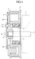
- the swash plate compressor 100 includes a cylinder block 32 defining six cylinder bores 33 around a shaft 7 in a housing 1. Each of the cylinder bores 33 houses a cylinder 48 axially slidable therein.
- the compressor 100 includes a front housing 4 defining a crank chamber 35 adjacent to the cylinder block 32.
- the compressor 100 includes a rear housing 6 which defines coolant suction chambers 37 and coolant discharge chamber 38 in communication with the cylinder bores 33.
- the cylinder bores 33 and coolant suction chambers 37, 38 are separated from each other by a valve plate 39.
- the valve plate 39 has inlets 53 and outlets 56 interconnecting cylinder bores and suction and discharge chambers 37, 38.
- the valve plate 39 has suction plates 54 which cover inlets 53 on the cylinder bores 33.
- the valve plate has discharge plates 55 which cover outlets 56 on the discharge chamber 38.
- the crank chamber 35 includes a drive plate 41 fixed to a shaft 7.
- the crank chamber 35 includes a sleeve 42 slidably fitted with the shaft 7.
- the crank chamber 35 includes a journal 44 swingably connected to shaft 7, using pin 43.
- the crank chamber 35 includes a swash plate 45 fixed to the outer end of journal 44.
- the journal 44 connects to an elongated arced hole 46 of drive plate 41 which restricts a swing motion.
- the pistons 48 are connected to the swash plate 45, using a pair of shoes 49, with the swash plate 45 interposed between shoes 49.
- the shaft 7 is connected to the pulley 4 for rotation.
- the pulley 4 is rotatably supported by bearing 3 on the front housing 1.
- the compressor 100 includes an electronic control valve 102 and a check valve 103 in a rear housing 36.
- the control valve 10 2 feeds a part of a compressed coolant in discharge chamber 38 to the crank chamber 35 through a passage 52 for regulating pressure in crank chamber 35.
- the swash plate 45 is controlled at an inclined angle by differential pressure between suction chamber 37 and crank chamber 35.
- the angular change of swash plate 45 changes stroke of each piston 48, which changes discharge volume of a coolant .
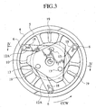
- clutchless compressor 100 has housing 1 with a boss 2.
- the boss 2 has the pulley 4 rotatably supported thereon, using the bearing 3.
- the pulley 4 has drive plate 5 fixed on the end face thereof, using a bolt.
- the drive plate 5 includes cylinder-shaped protrusions 6 on the side thereof.
- the protrusions 6 are arranged on the identical circle about shaft 7 at an angular interval.
- the pulley 4 and drive plate 5 constitutes a first transmission member or a driven member.
- the housing 1 is coaxial with the boss 2, and houses shaft 7 which projects outward from the boss 2.
- the shaft 7 has an end which is fixed to hub 10 (second transmission member or drive member), using a bolt 8 and a washer 9.
- hub 10 is shaped as a triangle.
- the hub 10 has pin insertion holes 11 (refer to Fig. 4), which are positioned on the identical circle about shaft 7 at an angular interval of 120 degree.
- the hub 10 connects with drive plate 5 , using belt-plate shaped leaf springs or links 12A of the identical shape and dimension.
- the leaf spring 12A is made of a spring of a high-carbon steel.
- the leaf springs 12A are arranged between drive plate 5 and hub 10 and parallel with a direction normal to the shaft 7. For example, the leaf springs 12A extend tangentially from hub 10 to pulley.
- each of leaf springs 12A has a through-hole 14 at one longitudinal end, which is rotatably fitted with the outer periphery of pin (protrusion) 13 that passes through insertion-hole 11.
- Each of the leaf springs 12A has a second through-hole 15 at the other longitudinal end, which is rotatably fitted with the outer periphery of a protrusion 6.
- Each of the leaf springs 12A has a slit 16 extending longitudinally from one end edge toward the other end and over the first through-hole 14.
- One end of leaf spring 12A includes a pair of side pieces 12Aa, 12Ab opposed to each other.
- Each of side pieces 12Aa, 12Ab defines slit 16 and first through-hole 14 therebetween.
- the f irst through-hole 14 is slightly smaller in size than the pin 13. The fitting of pin 13 into the first through-hole 14 allows the inner periphery of first through-hole 14 to be pressed against the outer periphery of pin 13 under a resilient force of leaf spring 12A. This allows the both peripheries to be in tight contact with each other without gap.
- compressor 100 produces seizing inside thereof, and load torque become over a predetermined value.
- the width of slit 16 is set for the pin 13 fitted in first through-hole 14 to press and widen the slit 16 to come out of the slit 16 outside.
- Each of leaf springs 12A has a slit 18 extending longitudinally from the second through-hole 15 toward the other end.
- the second through-hole 14 is slightly smaller in size than protrusion 6.
- the protrusion 6 is pressed into the second through-hole 15 before the head of protrusion 6 is riveted.
- the pressing allows the inner periphery of second through-hole 15 to be pressed against the outer periphery of protrusion 6 under resilient force by leaf spring 12, thus eliminating gap between the both peripheries.
- the riveting of the head of protrusion 6 as a flange prevents the leaf spring 12A from coming out of protrusion 6, as shown in Fig. 4.
- Power of the engine 101 is applied to pulley 4 through the belt B. It is supposed that load torque on the compressor is lower than a predetermined value. Power from engine 101 is transmitted to hub 10 through the protrusion 6, leaf spring 12A, and pin 13, rotating shaft 7. The rotating shaft 7 rotates swash plate 45 to control the stroke of pistons 48.
- each of pins 13 is firmly pressed against the portion of slit 16 in proximity to the tip end of leaf spring 12A.
- the portion of slit 16 or side pieces 12Aa, 12Ab are pressed and widened transversely. This allows the pin 13 fitted in the first through-hole 14 to be disengaged from the leaf spring 12A through the slit 16.
- the disengagement cuts off transmission of power from pulley 4 to shaft 7, thus idling pulley 4.
- the pin 13 may be replaced by a resilient cylinder, which is resiliently deformed to pass through the slit 16.
- the leaf spring 12A of a spring or resilient material resists time-varying or wearing, and the leaf spring 12A is deformed to cut off transmission of power. This stabilizes the threshold value of load torque, achieving accurate cutting-off of transmission of power.
- the embodiment is structured as the leaf springs 12A of the identical shape and dimension are arranged symmetrically about shaft 7 at an equal angular interval.
- the arrangement reduces influence on leaf springs 12A due to variation of strength and dimension, and advantageously facilitates to cut off power due to the threshold value of a desired load torque.
- Each of leaf springs 12A disengaged from pin 13 is rotatable about protrusion 6.
- a leaf spring 12A hits upon a neighboring pin 13 to rotate toward the outer periphery of pulley 4.
- the leaf spring 12A runs on and locks with protrusion-shaped locking member 19 formed to drive plate 5, under centrifugal force (refer to Fig. 7). In the state, the hub 10 and pin 13 do not contact with the leaf spring 12A, and noise does not occur.
- the power transmission has a simple structure, and the small number of components and production steps in comparison with the conventional art's one. This shortens productive time and reduces productive cost.
- Each of the leaf springs 12A in a plate-shape is arranged between the drive plate 5 and hub 10 and parallel to a direction normal to the shaft 7.
- the shaft 7 has a small dimension in an axial direction, which advantageously facilitates installation of the clutchless compressor at a position.
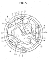
- the embodiment has protrusions 20 formed integrally to the face of hub 10 in opposite to the hub 10, in place of the pins 13 of the first embodiment.
- the protrusions 20 are fitted in one ends of leaf springs 12A.
- the other ends of leaf springs 12A has protrusions 6 rotatably fitted therein.
- the protrusions 6 are integrally formed to the pulley 4. This further reduces the number of components, which shortens productive time and reduces productive cost.
- the leaf springs 12A are interposed between the hub 10 and pulley 4, and are restricted to move in a thickness direction thereof. This requires no riveting of protrusions 6 for preventing of leaf springs 12A from coming out of protrusions 6. This further reduces productive cost.
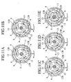
- respective leaf springs 12B include a pair of bifurcate side pieces 12Ba, 12Bb connected to each other.
- Each of leaf springs 12B has the side pieces 12Ba, 12Bb on one end side, which radially crimp the outer periphery of protrusion 6.
- Each of leaf springs 12B has the other end side rotatably supported by pin 13.
- Leaf spring 12B has two plates 12B1, 12B2 of the identical shape and dimension. The plates 12B1, 12B2 are stamped out in a shape, and are stacked on each other in the thickness direction. This facilitates stamping for enhancing workability, and resists burr and deformation for enhancing dimensional accuracy.
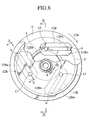
- the embodiment has a locking member 19 of a resilient member as a washer.
- the locking member 19 is fitted concentrically with the outer periphery of shaft part 10a of hub 10.
- the locking member has a peripheral edge bent toward the flange 10 of hub 10.
- the locking member 19 slidably presses respective leaf springs 21B against the rear side of flange 10b of hub 10 for locking.
- each of protrusions 6 presses and widens the ends of the side pieces 12Ba, 12Bb on one end side of leaf spring 12B, disengaging from the leaf spring 12B. The disengagement cuts off transmission of power from the pulley 4 to hub 10.
- each of leaf springs 12B comes against a protrusion 6 that rotates along an orbit T indicated by the dotted line.
- leaf springs 12B rotate inside of the orbit, sliding on the locking member 19. The leaf springs 12B is locked in a region without contacting protrusions 6.
- the leaf springs 12B disengages from pulley 4 rotating after cutting off transmission of power. In the case, leaf springs 12B does not rotate during maintenance. Thus, the embodiment prevents hitting of the leaf springs 12B upon an operator and injury to the operator.
- the clearance between the leaf spring 12B and pulley 4 requires width X more than a predetermined size, as referred in Fig. 9.
- a shim is required to be inserted between the tip face of shaft 7 and hub 10 for adjustment.
- the locking member 19 presses the leaf springs 12B against hub 10. This ensures a width X more than a predetermined size, advantageously saving time for adjustment.
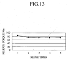
- release torque of leaf spring 12B and protrusion 6 is repeatedly measured five times .
- the test' s object is the identical leaf spring 12B and protrusion 6. That is, after disengagement of the leaf spring 12B and protrusion 6 from each other, the leaf spring 12B and protrusion 6 is engaged again for test. As a result, release torques are stabilized at about 80 Nm.
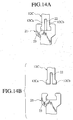
- a leaf spring 12C has an end with both sides projecting transversely outward.
- the leaf spring 12C has side-pieces 12Ca, 12Cb at the end.
- the side pieces 12Ca, 12Cb are opposed to each other, with a slit 22 intervening between the side-pieces 12Ca, 12Cb at the end.
- the side pieces 12Ca, 12Cb are resiliently deformable.
- the slit 22 extends longitudinally from the end edge to the other end of the leaf spring 12C .
- the hub 10 has locking parts 21 with fitting recess 23 in which the end of leaf spring 12C is fitted.
- the cluthless compressor has a load torque less than a predetermined value.
- the side-pieces 12Ca, 12Cb at the end of leaf spring 12C is maintained to fit in the fitting recess 23 of locking part 21, as shown in Fig. 14A.
- the end or side pieces 12Ca, 12Cb of leaf spring 12C is resiliently deformed, with the width being reduced.
- the leaf spring 12C is disengaged from the fitting recess 23, thus cutting off power, as shown in Fig. 14B.
- a power transmission is manufactured with the small number of components and production steps. This shortens productive time and reduces productive cost.
- the arrangement of a link reduces a shaft in the axial dimension.
- the link does not contact with the other member of the driven member and the drive member after cutting off power, and noise does not occurs.
- the invention requires no riveting for preventing of the link from coming out of a first or second engagement member. This further shortens productive time and reduces productive cost.
- the link includes plates of an identical shape and dimension, which enhances workability during stamping and dimensional accuracy.
- torque is further stabilized, when excessive torque cuts off transmission of power.
- the link resists time-varying or wearing, which stabilizes the threshold value of load torque, enhancing reliability.
Landscapes
- Engineering & Computer Science (AREA)
- Mechanical Engineering (AREA)
- General Engineering & Computer Science (AREA)
- Manufacturing & Machinery (AREA)
- Compressors, Vaccum Pumps And Other Relevant Systems (AREA)
- Transmission Devices (AREA)
Applications Claiming Priority (8)
| Application Number | Priority Date | Filing Date | Title |
|---|---|---|---|
| JP2002306139 | 2002-10-21 | ||
| JP2002306124 | 2002-10-21 | ||
| JP2002306124 | 2002-10-21 | ||
| JP2002306139 | 2002-10-21 | ||
| JP2003008309 | 2003-01-16 | ||
| JP2003008315 | 2003-01-16 | ||
| JP2003008315A JP4195617B2 (ja) | 2002-10-21 | 2003-01-16 | 動力伝達装置 |
| JP2003008309A JP4195616B2 (ja) | 2002-10-21 | 2003-01-16 | 動力伝達装置 |
Publications (2)
| Publication Number | Publication Date |
|---|---|
| EP1413751A1 true EP1413751A1 (fr) | 2004-04-28 |
| EP1413751B1 EP1413751B1 (fr) | 2006-07-26 |
Family
ID=32074571
Family Applications (1)
| Application Number | Title | Priority Date | Filing Date |
|---|---|---|---|
| EP03023830A Expired - Lifetime EP1413751B1 (fr) | 2002-10-21 | 2003-10-20 | Mécanisme de transmission de puissance et compresseur |
Country Status (3)
| Country | Link |
|---|---|
| US (1) | US7540719B2 (fr) |
| EP (1) | EP1413751B1 (fr) |
| DE (1) | DE60307011T2 (fr) |
Cited By (2)
| Publication number | Priority date | Publication date | Assignee | Title |
|---|---|---|---|---|
| EP2977632A4 (fr) * | 2013-03-21 | 2017-04-19 | Ogura Clutch Co., Ltd. | Dispositif de transmission d'énergie |
| US20190309821A1 (en) * | 2018-04-10 | 2019-10-10 | Optimized Solutions, LLC | Low frequency torsional spring-damper |
Families Citing this family (5)
| Publication number | Priority date | Publication date | Assignee | Title |
|---|---|---|---|---|
| EP1646796B1 (fr) * | 2003-07-18 | 2006-11-02 | Calsonic Kansei Corporation | Element de couplage |
| US8011063B2 (en) * | 2007-02-05 | 2011-09-06 | Nilfisk-Advance A/S | Overload clutch for rotating agitation member in cleaning machine |
| US9145877B2 (en) * | 2011-11-22 | 2015-09-29 | Thermo King Corporation | Compressor unloading device |
| TW201431658A (zh) * | 2013-02-05 | 2014-08-16 | Briview Corp | 傳動輪及傳動輪系統 |
| US20150273983A1 (en) * | 2014-03-31 | 2015-10-01 | Gn1 Co., Ltd. | Vehicle clutch having power transmission interruption unit |
Citations (6)
| Publication number | Priority date | Publication date | Assignee | Title |
|---|---|---|---|---|
| US4287974A (en) * | 1979-10-17 | 1981-09-08 | Coin Acceptors, Inc. | Clutch assembly for vending control system |
| JPH08121333A (ja) * | 1994-10-19 | 1996-05-14 | Toyota Autom Loom Works Ltd | クラッチレス圧縮機における動力伝達構造 |
| JPH08135752A (ja) * | 1994-09-14 | 1996-05-31 | Nippondenso Co Ltd | 動力伝達装置 |
| JPH10267048A (ja) * | 1997-03-25 | 1998-10-06 | Sanden Corp | 動力伝達機構 |
| EP0922875A2 (fr) * | 1997-12-11 | 1999-06-16 | Kabushiki Kaisha Toyoda Jidoshokki Seisakusho | Transmission limiteur de couple |
| EP1179678A2 (fr) * | 2000-08-11 | 2002-02-13 | Kabushiki Kaisha Toyota Jidoshokki | Dispositif d'accouplement |
Family Cites Families (25)
| Publication number | Priority date | Publication date | Assignee | Title |
|---|---|---|---|---|
| US1865559A (en) * | 1930-02-21 | 1932-07-05 | Montgrand Leon De | Mechanical coupling |
| US2256781A (en) * | 1940-09-06 | 1941-09-23 | Cotta Transmission Corp | Overload release mechanism |
| US2673633A (en) * | 1947-04-22 | 1954-03-30 | Self Changing Gear Company Ltd | Torque and speed responsive clutch |
| JPS4717032U (fr) | 1971-03-31 | 1972-10-27 | ||
| JPS4859254U (fr) | 1971-11-05 | 1973-07-27 | ||
| US4825992A (en) * | 1987-12-21 | 1989-05-02 | Alfred Skrobisch | Magnetic torque limiting clutch having overload disconnection means |
| JP2988978B2 (ja) | 1989-11-10 | 1999-12-13 | 日立金属株式会社 | シート材料切断装置 |
| US5683299A (en) * | 1994-09-14 | 1997-11-04 | Nippondenso Co., Ltd. | Device for transmitting rotational power |
| JP3980693B2 (ja) | 1997-01-14 | 2007-09-26 | サンデン株式会社 | プーリー直結型圧縮機 |
| JPH10252772A (ja) | 1997-03-17 | 1998-09-22 | Sanden Corp | 動力伝達機構 |
| JPH10267047A (ja) | 1997-03-25 | 1998-10-06 | Sanden Corp | 動力伝達機構 |
| JP3939393B2 (ja) * | 1997-05-08 | 2007-07-04 | サンデン株式会社 | 動力伝達機構 |
| JP2000087850A (ja) | 1998-09-10 | 2000-03-28 | Zexel Corp | クラッチレス圧縮機 |
| JP2000161382A (ja) | 1998-11-25 | 2000-06-13 | Ogura Clutch Co Ltd | 動力伝達装置 |
| JP2000192992A (ja) | 1998-12-25 | 2000-07-11 | Toyota Autom Loom Works Ltd | 動力伝達機構 |
| JP2001108070A (ja) | 1999-10-07 | 2001-04-20 | Ntn Corp | エアコンディショナ用プーリユニット |
| JP2001343025A (ja) * | 2000-03-29 | 2001-12-14 | Toyota Industries Corp | 動力伝達機構 |
| JP2003028191A (ja) | 2001-07-19 | 2003-01-29 | Ogura Clutch Co Ltd | 動力伝達機構 |
| JP2003035322A (ja) | 2001-07-24 | 2003-02-07 | Ogura Clutch Co Ltd | 動力伝達機構 |
| JP2003035321A (ja) | 2001-07-24 | 2003-02-07 | Ogura Clutch Co Ltd | 動力伝達機構 |
| JP2003056595A (ja) | 2001-08-09 | 2003-02-26 | Ogura Clutch Co Ltd | 動力伝達機構 |
| JP2003139161A (ja) | 2001-10-31 | 2003-05-14 | Ogura Clutch Co Ltd | 動力伝達機構 |
| JP4025056B2 (ja) | 2001-11-09 | 2007-12-19 | 小倉クラッチ株式会社 | 動力伝達機構 |
| JP4195617B2 (ja) | 2002-10-21 | 2008-12-10 | カルソニックカンセイ株式会社 | 動力伝達装置 |
| JP4195616B2 (ja) | 2002-10-21 | 2008-12-10 | カルソニックカンセイ株式会社 | 動力伝達装置 |
-
2003
- 2003-10-20 DE DE60307011T patent/DE60307011T2/de not_active Expired - Lifetime
- 2003-10-20 EP EP03023830A patent/EP1413751B1/fr not_active Expired - Lifetime
- 2003-10-20 US US10/687,741 patent/US7540719B2/en not_active Expired - Fee Related
Patent Citations (6)
| Publication number | Priority date | Publication date | Assignee | Title |
|---|---|---|---|---|
| US4287974A (en) * | 1979-10-17 | 1981-09-08 | Coin Acceptors, Inc. | Clutch assembly for vending control system |
| JPH08135752A (ja) * | 1994-09-14 | 1996-05-31 | Nippondenso Co Ltd | 動力伝達装置 |
| JPH08121333A (ja) * | 1994-10-19 | 1996-05-14 | Toyota Autom Loom Works Ltd | クラッチレス圧縮機における動力伝達構造 |
| JPH10267048A (ja) * | 1997-03-25 | 1998-10-06 | Sanden Corp | 動力伝達機構 |
| EP0922875A2 (fr) * | 1997-12-11 | 1999-06-16 | Kabushiki Kaisha Toyoda Jidoshokki Seisakusho | Transmission limiteur de couple |
| EP1179678A2 (fr) * | 2000-08-11 | 2002-02-13 | Kabushiki Kaisha Toyota Jidoshokki | Dispositif d'accouplement |
Non-Patent Citations (2)
| Title |
|---|
| PATENT ABSTRACTS OF JAPAN vol. 1996, no. 09 30 September 1996 (1996-09-30) * |
| PATENT ABSTRACTS OF JAPAN vol. 1999, no. 01 29 January 1999 (1999-01-29) * |
Cited By (3)
| Publication number | Priority date | Publication date | Assignee | Title |
|---|---|---|---|---|
| EP2977632A4 (fr) * | 2013-03-21 | 2017-04-19 | Ogura Clutch Co., Ltd. | Dispositif de transmission d'énergie |
| US20190309821A1 (en) * | 2018-04-10 | 2019-10-10 | Optimized Solutions, LLC | Low frequency torsional spring-damper |
| US10612620B2 (en) * | 2018-04-10 | 2020-04-07 | Optimized Solutions, LLC | Low frequency torsional spring-damper |
Also Published As
| Publication number | Publication date |
|---|---|
| EP1413751B1 (fr) | 2006-07-26 |
| US20040086392A1 (en) | 2004-05-06 |
| US7540719B2 (en) | 2009-06-02 |
| DE60307011D1 (de) | 2006-09-07 |
| DE60307011T2 (de) | 2006-11-23 |
Similar Documents
| Publication | Publication Date | Title |
|---|---|---|
| US20030106763A1 (en) | Power transmission mechanism | |
| US6068452A (en) | Torque limiting mechanism | |
| JPH08135752A (ja) | 動力伝達装置 | |
| US7540719B2 (en) | Power transmission and compressor | |
| EP1146240A2 (fr) | Mécanisme limiteur de couple | |
| US5556261A (en) | Piston type compressor | |
| US6471024B2 (en) | Torque limiting mechanism | |
| US6612813B2 (en) | Power transmission mechanism | |
| EP1197672A1 (fr) | Mecanisme de transmission de puissance | |
| US20010027134A1 (en) | Torque limiting mechanism | |
| US20040052647A1 (en) | Compressor | |
| EP1316451A2 (fr) | Dispositif de rotation d'un véhicule | |
| US7314415B2 (en) | Coupling member | |
| US20090214360A1 (en) | Tilting plate type compressor | |
| US20060172830A1 (en) | Power transmission device, method for manufacturing the same and compressor | |
| US20020086750A1 (en) | Power transmitting mechanism | |
| US20120247319A1 (en) | Swash plate type variable displacement compressor | |
| JPH10318280A (ja) | 動力伝達機構 | |
| US20070101859A1 (en) | Compressor | |
| KR102861984B1 (ko) | 스크롤 압축기 | |
| KR102936118B1 (ko) | 스크롤 압축기 | |
| JP2003254402A (ja) | トルクリミッタを有する動力伝達装置 | |
| JP2003214336A (ja) | 冷媒圧縮機 | |
| KR20130109499A (ko) | 사판식 압축기의 구동축 지지구조 | |
| JP2009250117A (ja) | 斜板式圧縮機 |
Legal Events
| Date | Code | Title | Description |
|---|---|---|---|
| PUAI | Public reference made under article 153(3) epc to a published international application that has entered the european phase |
Free format text: ORIGINAL CODE: 0009012 |
|
| AK | Designated contracting states |
Kind code of ref document: A1 Designated state(s): AT BE BG CH CY CZ DE DK EE ES FI FR GB GR HU IE IT LI LU MC NL PT RO SE SI SK TR |
|
| AX | Request for extension of the european patent |
Extension state: AL LT LV MK |
|
| 17P | Request for examination filed |
Effective date: 20040623 |
|
| AKX | Designation fees paid |
Designated state(s): DE FR GB |
|
| 17Q | First examination report despatched |
Effective date: 20050418 |
|
| GRAP | Despatch of communication of intention to grant a patent |
Free format text: ORIGINAL CODE: EPIDOSNIGR1 |
|
| GRAS | Grant fee paid |
Free format text: ORIGINAL CODE: EPIDOSNIGR3 |
|
| GRAA | (expected) grant |
Free format text: ORIGINAL CODE: 0009210 |
|
| AK | Designated contracting states |
Kind code of ref document: B1 Designated state(s): DE FR GB |
|
| REG | Reference to a national code |
Ref country code: GB Ref legal event code: FG4D |
|
| REF | Corresponds to: |
Ref document number: 60307011 Country of ref document: DE Date of ref document: 20060907 Kind code of ref document: P |
|
| ET | Fr: translation filed | ||
| PLBE | No opposition filed within time limit |
Free format text: ORIGINAL CODE: 0009261 |
|
| STAA | Information on the status of an ep patent application or granted ep patent |
Free format text: STATUS: NO OPPOSITION FILED WITHIN TIME LIMIT |
|
| 26N | No opposition filed |
Effective date: 20070427 |
|
| PGFP | Annual fee paid to national office [announced via postgrant information from national office to epo] |
Ref country code: DE Payment date: 20121017 Year of fee payment: 10 Ref country code: FR Payment date: 20121018 Year of fee payment: 10 |
|
| PGFP | Annual fee paid to national office [announced via postgrant information from national office to epo] |
Ref country code: GB Payment date: 20121017 Year of fee payment: 10 |
|
| GBPC | Gb: european patent ceased through non-payment of renewal fee |
Effective date: 20131020 |
|
| REG | Reference to a national code |
Ref country code: DE Ref legal event code: R119 Ref document number: 60307011 Country of ref document: DE Effective date: 20140501 |
|
| PG25 | Lapsed in a contracting state [announced via postgrant information from national office to epo] |
Ref country code: GB Free format text: LAPSE BECAUSE OF NON-PAYMENT OF DUE FEES Effective date: 20131020 |
|
| REG | Reference to a national code |
Ref country code: FR Ref legal event code: ST Effective date: 20140630 |
|
| PG25 | Lapsed in a contracting state [announced via postgrant information from national office to epo] |
Ref country code: FR Free format text: LAPSE BECAUSE OF NON-PAYMENT OF DUE FEES Effective date: 20131031 Ref country code: DE Free format text: LAPSE BECAUSE OF NON-PAYMENT OF DUE FEES Effective date: 20140501 |