EP1179678A2 - Dispositif d'accouplement - Google Patents
Dispositif d'accouplement Download PDFInfo
- Publication number
- EP1179678A2 EP1179678A2 EP01119234A EP01119234A EP1179678A2 EP 1179678 A2 EP1179678 A2 EP 1179678A2 EP 01119234 A EP01119234 A EP 01119234A EP 01119234 A EP01119234 A EP 01119234A EP 1179678 A2 EP1179678 A2 EP 1179678A2
- Authority
- EP
- European Patent Office
- Prior art keywords
- arm
- transmitting mechanism
- power transmitting
- rotors
- rotor
- Prior art date
- Legal status (The legal status is an assumption and is not a legal conclusion. Google has not performed a legal analysis and makes no representation as to the accuracy of the status listed.)
- Withdrawn
Links
- 230000007246 mechanism Effects 0.000 title claims abstract description 55
- 230000008878 coupling Effects 0.000 claims description 21
- 238000010168 coupling process Methods 0.000 claims description 21
- 238000005859 coupling reaction Methods 0.000 claims description 21
- 230000002452 interceptive effect Effects 0.000 claims description 2
- 230000005540 biological transmission Effects 0.000 abstract description 107
- 230000008859 change Effects 0.000 description 6
- 238000004378 air conditioning Methods 0.000 description 5
- 238000006073 displacement reaction Methods 0.000 description 5
- 230000003247 decreasing effect Effects 0.000 description 3
- 238000010586 diagram Methods 0.000 description 3
- 239000003507 refrigerant Substances 0.000 description 3
- 230000002411 adverse Effects 0.000 description 2
- 230000006835 compression Effects 0.000 description 2
- 238000007906 compression Methods 0.000 description 2
- 230000005489 elastic deformation Effects 0.000 description 2
- 239000000446 fuel Substances 0.000 description 2
- 230000007257 malfunction Effects 0.000 description 2
- 238000007789 sealing Methods 0.000 description 2
- 230000005856 abnormality Effects 0.000 description 1
- 238000006243 chemical reaction Methods 0.000 description 1
- 238000011109 contamination Methods 0.000 description 1
- 238000001816 cooling Methods 0.000 description 1
- 230000007423 decrease Effects 0.000 description 1
- 239000000428 dust Substances 0.000 description 1
- 239000013013 elastic material Substances 0.000 description 1
- 239000003921 oil Substances 0.000 description 1
- 230000035939 shock Effects 0.000 description 1
- 239000004636 vulcanized rubber Substances 0.000 description 1
- XLYOFNOQVPJJNP-UHFFFAOYSA-N water Substances O XLYOFNOQVPJJNP-UHFFFAOYSA-N 0.000 description 1
Images


Classifications
-
- F—MECHANICAL ENGINEERING; LIGHTING; HEATING; WEAPONS; BLASTING
- F04—POSITIVE - DISPLACEMENT MACHINES FOR LIQUIDS; PUMPS FOR LIQUIDS OR ELASTIC FLUIDS
- F04B—POSITIVE-DISPLACEMENT MACHINES FOR LIQUIDS; PUMPS
- F04B27/00—Multi-cylinder pumps specially adapted for elastic fluids and characterised by number or arrangement of cylinders
- F04B27/08—Multi-cylinder pumps specially adapted for elastic fluids and characterised by number or arrangement of cylinders having cylinders coaxial with, or parallel or inclined to, main shaft axis
- F04B27/0873—Component parts, e.g. sealings; Manufacturing or assembly thereof
- F04B27/0895—Component parts, e.g. sealings; Manufacturing or assembly thereof driving means
-
- Y—GENERAL TAGGING OF NEW TECHNOLOGICAL DEVELOPMENTS; GENERAL TAGGING OF CROSS-SECTIONAL TECHNOLOGIES SPANNING OVER SEVERAL SECTIONS OF THE IPC; TECHNICAL SUBJECTS COVERED BY FORMER USPC CROSS-REFERENCE ART COLLECTIONS [XRACs] AND DIGESTS
- Y10—TECHNICAL SUBJECTS COVERED BY FORMER USPC
- Y10S—TECHNICAL SUBJECTS COVERED BY FORMER USPC CROSS-REFERENCE ART COLLECTIONS [XRACs] AND DIGESTS
- Y10S474/00—Endless belt power transmission systems or components
- Y10S474/903—Particular connection between hub and shaft
Definitions
- the present invention relates to a power transmitting mechanism that disconnects power transmission from a first rotor to a second rotor when an excessive torque (load) is transmitted between the first rotor and the second rotor.
- Japanese Unexamined Patent Publication No. 11-30244 discloses such a power transmitting mechanism, which has a rotor driven by an external drive source and a rotor for a device.
- the rotors are coupled to each other by a rubber part for transmitting power.
- the rubber part breaks.
- power transmission from one of the rotors to the other is disconnected. Accordingly, the mechanism prevents the external drive source from being affected by an excessive transmission torque.
- the present invention provides a power transmitting mechanism comprising a first rotor, a second rotor, and a coupler.
- the second rotor is coaxial to the first rotor and is driven by the first rotor.
- the coupler connects the first rotor to the second rotor such that the coupler uncouples when the torque transmitted by the coupler exceeds a predetermined value.
- the coupler includes a first coupling member and a second coupling member.
- the first coupling member is formed on the first rotor.
- the second coupling member is formed on the second rotor.
- One of the coupling members includes an arm. A distal end of the arm engages the other of the coupling members.
- the arm is disengaged from the other of the coupling members. The distal end moves in a generally radial direction of the rotors to a non-interfering position when the coupler uncouples.
- a power transmitting mechanism according to a first embodiment of the present invention will now be described.
- This embodiment relates to an air-conditioning system for a vehicle.
- a variable displacement swash plate type compressor is a driven auxiliary device and an engine is used as an external drive source.
- the power transmitting mechanism is in the power transmission path between the engine and the compressor.
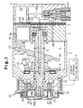
- the compressor includes a cylinder block 1, a front housing member 2, and a rear housing member 4.
- the front housing member 2 is secured to the front end of the cylinder block 1.
- the rear housing member 4 is secured to the rear end of the cylinder block 1.
- a valve plate 3 is secured between the cylinder block 1 and the rear housing member 4.
- the cylinder block 1, the front housing member 2, and the rear housing member 4 form the housing assembly of the compressor.
- the left side of the figure is defined as the front, and the right side of the figure is defined as the rear.
- a crank chamber 5 is defined between the cylinder block 1 and the front housing member 2.
- a drive shaft 6 is rotatably supported in the crank chamber 5.
- a lug plate 11 is located in the crank chamber 5 and is secured to the drive shaft 6 to integrally rotate with the drive shaft 6.
- the front end of the drive shaft 6 is coupled to the engine E of a vehicle by means of a power transmitting mechanism PT.
- the engine E functions as the external drive source.
- the power transmitting mechanism PT may be a clutch mechanism (such as an electromagnetic clutch), which selectively transmits and disconnects power by external electrical control.
- the power transmitting mechanism PT may also be a clutchless type mechanism (such as a combination of a belt and a pulley), which does not have a clutch mechanism and constantly transmits power.
- the clutchless type power transmitting mechanism PT is employed in the first embodiment.
- a power transmitting mechanism PT that is used with a clutch will be described in the second embodiment.
- a swash plate 12 is accommodated in the crank chamber 5.
- the swash plate 12 is supported by the drive shaft 6 to slide and to incline.
- a hinge mechanism 13 is arranged between the lug plate 11 and the swash plate 12. Accordingly, the swash plate 12 rotates integrally with the lug plate 11 and the drive shaft 6 by means of the hinge mechanism 13.
- the swash plate 12 inclines with respect to the drive shaft 6 while sliding along the axis of the drive shaft 6.
- Cylinder bores 1a (only one of the cylinder bores is shown in Fig. 1) are formed in the cylinder block 1 to encompass the drive shaft 6. Each cylinder bore 1a is formed through the cylinder block 1.
- a single-headed piston 20 is housed in each cylinder bore 1a.
- the valve plate 3 closes the rear opening of each cylinder bore 1a and the piston 20 closes the front opening of each cylinder bore 1a.
- a compression chamber is defined in each cylinder bore 1a. The volume of the compression chamber varies as each piston 20 reciprocates in the corresponding cylinder bore 1a.
- Each piston 20 is coupled to the periphery of Lhe swash plate 12 by a pair of shoes 19. Therefore, when the swash plate 12 rotates integrally with the drive shaft 6, rotation of the swash plate 12 reciprocates each piston 20 by means of the pair of shoes 19.
- a suction chamber 21 and a discharge chamber 22 are respectively defined between the valve plate 3 and the rear housing member 4.
- a suction port 23 and a suction valve 24, which selectively opens and closes the port 23, are formed in the valve plate 3 for each cylinder bore 1a.
- a discharge port 25 and a discharge valve 26, which selectively opens and closes the port 25, are formed in the valve plate 3 for each cylinder bore 1a.
- the suction chamber 21 and each cylinder bore 1a are connected by the corresponding suction port 23.
- Each cylinder bore 1a and the discharge chamber 22 are connected by the corresponding discharge port 25.
- each piston 20 from the top dead center to the bottom dead center draws refrigerant gas in the suction chamber 21 into the associated cylinder bore 1a through the corresponding suction port 23 and the corresponding suction valve 24.
- the movement of each piston 20 from the bottom dead center to the top dead center compresses the refrigerant gas drawn into the associated cylinder bore 1a, to a predetermined pressure. Then, the compressed refrigerant gas is discharged to the discharge chamber 22 through the corresponding discharge port 25 and the corresponding discharge valve 26.
- the inclination angle of the swash plate 12 is arbitrarily set between the maximum inclination angle (as shown in Fig. 1) and the minimum inclination angle by adjusting the internal pressure of the crank chamber 5 using an electromagnetic control valve CV.
- the crank chamber 5 and the suction chamber 21 are connected by a bleed passage 27.
- the discharge chamber 22 and the crank chamber 5 are connected by a supply passage 28, in which the electromagnetic control valve CV is located.
- the flow rate of highly pressurized discharge gas that is conducted to the crank chamber 5 from the discharge chamber 22 through the supply passage 28 is set by adjusting the opening degree of the electromagnetic control valve CV using a control apparatus, which is not shown in the figures.
- the internal pressure of the crank chamber 5 is determined by the relationship between the flow rate of gas entering the crank chamber 5 and the flow rate of gas that is flowing from the crank chamber 5 into the suction chamber 21 through the bleed passage 27.
- the difference between the internal pressure of the crank chamber 5 and the internal pressure of each cylinder bore 1a changes according to the internal pressure of the crank chamber 5.
- the inclination angle of the swash plate 12 is determined by this pressure difference. As a result, the stroke of each piston 20, or the displacement, is adjusted.
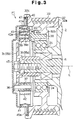
- a pulley 32 which functions as a first rotor, includes a cylindrical belt engaging member 32a and an annular support member 32b.
- a belt 33 which extends from the output axis of the engine E (refer to Fig. 1), is wrapped around the cylindrical belt engaging member 32a.
- the annular support member 32b is inward of the inner surface of the belt engaging member 32a.
- the support member 32b is rotatably supported by the support cylinder 31 through a bearing 34.
- the pulley 32 is located around the same axis as the axis L of the drive shaft 6 and rotates relative to the drive shaft 6.
- a receiving member 35 which functions as a second rotor, is secured to the front end of the drive shaft 6 to integrally rotate with the drive shaft 6.
- the rocciving member 35 includes a cylindrical member 35a and a disc-shaped hub 35b.
- the cylindrical member 35a is fitted on the front end of the drive shaft 6.
- the hub 35b is fitted into the front end of the cylindrical member 35a.
- Support pins 36 (four support pins are used in this embodiment) are secured to the periphery of the hub 35b at equal angular intervals (90 degrees in this embodiment) about the axis L.
- a cylindrical sleeve 37 is fitted on the periphery of each support pin 36 with an appropriate pressure. When a strong rotational force is applied to one of the sleeves 37, it can rotate relative to the corresponding support pin 36.
- Engaging pins 38 (four engaging pins are applied in this embodiment) are secured to the front surface of the support member 32b of the pulley 32 at equal angular intervals (90 degrees in this embodiment) about the axis L.
- a cylindrical roller 39 is rotatably supported by each engaging pin 38.
- the engaging pins 38 are further from the axis L than the support pins 36.
- an annular fitting groove 32c is formed at the front portion of the belt engaging member 32a.
- the periphery of an annular stopper 40 which is a flat ring, is fitted in the fitting groove 32c.
- a cylindrical limit ring 41 is connected to the pulley 32 by the inner edge of the stopper 40.
- the limit ring 41 is coaxial with the pulley 32 and encompasses the rollers 39.
- the middle section of the inner surface of Lhe limit ring 41 bulges inwardly, as shown, and forms a limit surface 41a.
- a power transmission arm 42 is formed by a leaf spring and is located between each sleeve 37 and one of the rollers 39. The proximal end of each power transmission arm 42 is securely wound around the sleeve 37 of the corresponding support pin 36. Each power transmission arm 42 extends from the corresponding sleeve 37 toward the corresponding roller 39 in a clockwise direction as viewed from the perspective of Fig. 2. Each power transmission arm 42 is slightly arched toward the periphery of the pulley 32 as shown.
- each power transmission arm 42 is between the corresponding roller 39 and the limit surface 41a of the limit ring 41. In other words, the distal end of each power transmission arm 42 is closer to the periphery of the pulley 32 than the corresponding roller 39.
- the distal end of each power transmission arm 42 curves inwardly as shown in Fig. 2. Therefore, a curved end 43, which is hooked around the corresponding roller 39, is formed at the distal end of each power transmission arm 42.
- each power transmission arm 42 of the receiving member 35 is engaged with the corresponding roller 39 by the curved end 43.
- the receiving member 35 and the pulley 32 are connected with each other by the arms 42 to transmit power and to rotate relative to one another within a predetermined angular range while transmitting power.
- each roller 39 and the corresponding curved end 43 are located about the axis L of the rotors 32, 35.
- Each roller 39 is radially inward of the corresponding curved end 43.
- Each power transmission arm 42 is supported by the receiving member 35 and the corresponding support pin 36.
- the support pins 36 are closer to the axis L than the corresponding curved ends 43.
- a fulerum portion 44 is formed on a back surface 42a of each power transmission arm 42 to oppose the limit surface 41a of the limit ring 41.
- the fulcrum portions are formed by, for example, attaching a piece of vulcanized rubber to each arm 42.
- Each fulcrum portion 44 is compressed between the back surface 42a of the corresponding power transmission arm 42 and the limit surface 41a of the limit ring 41.
- Each power transmission arm 42 is pressed against the corresponding roller 39 by the repulsive force of the corresponding fulcrum portion 44.
- the cylindrical surface 39a of each roller 39 is pressed against a concave surface 43a of the corresponding curved end 43 of each power transmission arm 42.
- the radius of curvature of the cylindrical surface 39a of each roller 39 is less than the radius of curvature of the concave surface 43a inside the corresponding curved end 43, thus linear contact occurs between each cylindrical surface 39a and the corresponding concave surface 43a.
- each curved end 43 is curved.
- the contact point between the cylindrical surface 39a of each roller 39 and the concave surface 43a of the corresponding curved end 43 moves toward the distal end or toward the proximal end of the corresponding power transmission arm 42 when one of the rollers 39 and the corresponding power transmission arm 42 move relative to one another.
- each roller 39 applies force to the corresponding power transmission arm 42 in an outward direction when the pulley 32 is driven.
- a cover 45 has a cylindrical shape with a closed end.
- a flange 45a which is formed at the periphery of the cover 45, is fitted in the fitting groove 32c together with the outer edge of the stopper 40.
- the cover 45 is used to cover the front end of the pulley 32.
- Each member that transmits power between the pulley 32 and the drive shaft 6 (receiving member 35, support pins 36, engaging pins 38, rollers 39, limit ring 41, and power transmission arms 42) is accommodated in the space between the cover 45 and the pulley 32.
- An annular sealing member 47 is fitted in the fitting groove 32c along a side wall surface. The sealing member 47 contacts the flange 45a of the cover 45 to seal the space between the cover 45 and the pulley 32.
- the engine E transmits power to the pulley 32 via the belt 33.
- the power is then transmitted to the receiving member 35 by the rollers 39 and the power transmission arms 42.
- the power is then transmitted to the drive shaft 6 of the compressor.
- Load torque is generated between the receiving member 35 of the compressor and the pulley 32 of the engine E during power transmission.
- the load torque causes each roller 39 and the corresponding power transmission arm 42 to move relative to one another, which causes the pulley 32 and the receiving member 35 to rotate relative to one another.
- each roller 39 and the corresponding power transmission arm 42 tend to move relative to one another.
- the contact points between them move toward the distal ends of the power transmission arms 42.
- the location where the fulcrum portion 44 presses against the limit surface 41a of the limit ring 41 functions as a fulcrum.
- the distal end of the power transmission arm 42 is elastically deformed generally outward. That is, the power transmission arm 42 is elastically deformed based on the load torque.
- the curved end 43 changes attitude with respect to the receiving member 35, in other words, the concave surface 43a is deformed.
- each roller 39 further elastically deforms the corresponding power transmission arm 42 and relatively moves to the distal end of the corresponding power transmission arm 42.
- each roller 39 rotates along the corresponding concave surface 43a and the contact point further moves toward the distal end of the corresponding power transmission arm 42. Accordingly; the relative rotation angle between the pulley 32 and the receiving member 35 is increased.
- each roller 39 rotates along the concave surface 43a and the contact point moves to the proximal end of the corresponding power transmission arm 42. Accordingly, the relative rotation angle of the pulley 32 and the receiving member 35 is decreased.
- the output torque of the engine E or the driving torque of the auxiliary equipment fluctuates.
- the power that is transmitted from the pulley 32 to the receiving member 35 varies.
- the position of the contact point is changed repeatedly.
- the pulley 32 repeats relative rotation in the clockwise and counter-clockwise direction within the predetermined angular range.
- the fluctuation of power that is transmitted from the pulley 32 to the receiving member 35 is suppressed.
- each power transmission arm 42 is closer to the periphery of the pulley 32 than the roller 39 just after the arm 42 comes off the roller 39. However, the curved end 43 of each power transmission arm 42 is moved closer to the center of the pulley 32 than the roller 39 after the pulley rotates by a quarter revolution, or in other words, after each roller 39 contacts the corresponding power transmission arm 42 at the back surface 42a.
- Each support pin 36 is inserted in the corresponding sleeve 37 with an appropriate pressure.
- rollers 39 do not interfere with the power transmission arms 42 (or curved ends 43).
- power transmission between the pulley 32 and the receiving member 35 is reliably disconnected.
- This structure prevents the roller 39 and the power transmission arm 42 from hitting each other repeatedly and thus causing noise and vibration.
- This embodiment provides the following advantages.
- the invention minimizes the loss of fuel efficiency by reliably discontinuing power transmission between the pulley 32 and the receiving member 35 when the load torque between the pulley 32 and the receiving member 35 is excessive.
- each power transmission arm 42 is changed by rotating it about the corresponding support pin 36 when the curved ends 43 and the corresponding rollers 39 are disengaged. Therefore, compared with a structure that changes the position of the power transmission arm 42 by deformation, the change of position is performed more smoothly.
- the rollers 39 and the engine E are used for changing the position of the power transmission arms 42. Accordingly, no special member, such as springs, is required for changing the position of the power transmission arms 42. Thus, the structure of the power transmitting mechanism is simplified.
- each roller 39 rolls along the concave surface 43a of the corresponding curved end 43 repeatedly against the friction between the cylindrical surface 39a and the concave surface 43a. This reduces torque shock applied to the engine.
- Each roller 39 rotates while sliding along the concave surface 43a of the corresponding curved end 43.
- an engaging pin 38 which does not rotate while directly contacting the concave surface 43a of the corresponding curved end 43 (such an engaging pin is also within the concept of the present invention)
- the likelihood of a malfunction in slidability is reduced.
- fluctuation of power transmission is effectively suppressed.
- each roller 39 smoothly rolls on the corresponding concave surface 43a. This permits smooth relative rotation between the pulley 32 and the receiving member 35. Thus, smooth power transmission is achieved, and fluctuation of power transmission is effectively suppressed.
- Each curved end 43 is connected Lo the hub 35b by means of the corresponding power transmission arm 42, which functions as an elastic member.
- each curved end 43 changes position with respect to the hub 35b by elastic deformation of the corresponding power transmission arm 42.
- the elastic arms 42 add elasticity to the transmission apparatus. Compared with a case, for example, where separate elastic members are provided in addition to the coupler, the number of power transmission members are reduced.
- the position of the contact point changes along the concave surface 43a repeatedly when the transmitted power varies. Accordingly, the distance between the contact point and the fulcrum of the deformation of the corresponding power transmission arm 42 (contact point between each fulcrum portion 44 and the limit ring 41) changes.
- the modulus of elasticity of the power transmission arm 42 and resonance frequency constantly change accordingly.
- the mechanism prevents the resonance from being generated by the vibration of the relative rotation, which is based on the variation of the transmitted power, of the pulley 32 and the receiving member 35.
- Each power transmission arm 42 is formed by a leaf spring.
- Each curved end 43 is formed by curving the corresponding power transmission arm 42. Therefore, the curved ends 43 are easily formed.
- Each power transmission arm 42 elastically deforms in the radial direction of the pulley 32 (each curved end 43 changes shape) when the torque is transmitted.
- Each power transmission arm 42 also rotates to position inwardly in the radial direction of the pulley 32 when the torque transmission is disconnected. Therefore, no space is required in the direction of the axis L for deformation and rotation of each power transmission arm 42.
- the size of the power transmitting mechanism PT more specifically, the size of the compressor, which has the power transmitting mechanism PT, is miniaturized in the direction of axis L. The space allotted for the compressor in an engine compartment of a vehicle is limited.
- the power transmitting mechanism PT in the first embodiment has a suitable structure for a compressor of a vehicle air-conditioning system.
- the elastic deformation of each power transmission arm 42 does not generate the reaction force in the direction of axis L of the drive shaft 6.
- the mechanism prevents force from acting on the compressor in the direction of axis L, which adversely affects the compressor.
- the pulley 32 includes the cover 45.
- Each member that transmits power (such as the receiving member 35, the support pins 36, the engaging pins 38, the rollers 39, the limit ring 41, and the power transmission arms 42) is accommodated in the space between the cover 45 and the pulley 32.
- This structure prevents foreign objects and water, oil, or dust in the engine compartment of a vehicle from affecting the transmission parts. Thus, wear resulting from the contamination of the members is eliminated.
- the structure also prevents foreign objects from being caught between the cylindrical surface 39a of each roller 39 and the concave surface 43a of the corresponding curved end 43. Accordingly, smooth rotation of the rollers 39 is maintained.
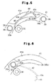
- a pulley 32 has an electromagnetic clutch, which selectively transmits and disconnects power by external electrical control, as shown in Fig. 7.
- a cover 45 is supported by a hub 35b of a receiving member 35.
- a leaf spring 51 is located hetween the cover 45 and the hub 35b.
- An armature 52 is secured to the cover 45 and is located between the pulley 32 and a limit ring 41. Engaging pins 38 are secured to the armature 52.
- the limit ring 41 is not engaged with the pulley 32 and is fitted on the power transmission arm 42.
- a core 53 is located at the rear of the pulley 32 in the front housing member 2.
- a compressor may be stopped by an external control when air-conditioning is not required.
- loss of power of an engine E is reduced.
- the power transmission arms 42 may be rigid bodies in the above embodiments.
- the limit ring 41 may be formed of an elastic material, which elastically deforms to radially expand and contract.
- each power transmission arm 42 (curved end 43) rotates about the corresponding support pin 36 according to the load torque when the roller 39 and the curved end 43 are engaged.
- each curved end 43 changes position with respect to the receiving member 35.
- the engaging pins 38 may be closer to the axis L than the pins 36.
- four pairs of rollers 39 and power transmission arms 42 are provided.
- the number of pairs is not limited to four, but may be six, five, three, two, or one. If the number of the pairs is reduced, the assembly of the power transmitting mechanism is simplified and the cost is reduced. If the number of the pairs is increased, the amount of transmission torque transmitted by each pair is reduced. Thus the endurance of each roller 39 and the corresponding power transmission arm 42 is improved. In other words, the endurance of the power transmitting mechanism PT is improved.
- a part of the back surface 42a of each power transmission arm 42 may be deformed to integrally form the fulcrum portion 44.
- Balls may be used instead of rollers 39 as a rotating element.
- the rollers may be arranged to change position with respect to the rotor on which the rollers are located, instead of the curved ends.
- the curved ends 43 may be fixed instead of Lhe engaging pins 38.
- the rollers 39 may be provided on the distal ends of Lhe power transmission arms 42 to engage with the corresponding curved ends 43.
- Both curved ends 43 and the rollers 39 may be arranged to change position with respect to the rotors 32 and 35, respectively.
- a spring which urges each power transmission arm 42 radially inward, may be provided between each power transmission arm 42 and the corresponding receiving member 35. Each spring changes the position of the corresponding power transmission arm 42. Each spring may be arranged to pull the corresponding power transmission arm 42 toward the drive shaft 6. Each spring may also be provided between one of the support pins 36 and the corresponding sleeve 37 to rotate the sleeve 37. In this case, when the rollers 39 and the corresponding power transmission arms 42 are disengaged, the power transmission arms 42 rotate to the withdrawn position without contacting the rollers 39. That is, the corresponding power transmission arms 42 change position with respect to the receiving member 35. This reliably prevents noise and vibration caused by collision of the arms 42 and the rollers 39.
- the second embodiment may be modified to include an electromagnetic clutch structure between the receiving member 35 and the drive shaft 6.
- the use of the torque transmitting mechanism of the above embodiments is not limited to power transmission between an engine E and an air-conditioning compressor.
- the mechanism may be used for power transmission between an engine E and any auxiliary device (such as a hydraulic pump for a power steering apparatus or a cooling fan for a radiator).
- the application of the power transmitting mechanism of the above embodiments is not limited to a power transmission path of a vehicle.
- the mechanism may be used for a power transmission path between a drive source and in a machine tool.
- the power transmitting mechanism of the above embodiments has general versatility and may be applied to any power transmission path.
- a power transmitting mechanism transmits power from an engine to a drive shaft (6) of a compressor.
- a pulley (32) is supported by the compressor and is coupled to the engine.
- a hub (35b) is attached to the drive shaft (6).
- Rollers (39) are located on the pulley (32).
- Elastic transmission arms (42) are located between the pulley (32) and the hub (35b). The distal end of each arm (42) is curved, and the proximal end is coupled to the hub (35b). When the rollers are engaged with the arms (42), power is transmitted between the pulley (32) and the hub (35b). When, due to excessive torque, the rollers (39) escape from the corresponding arm (42), power transmission between the pulley (32) and the hub (35b) is disconnected.
- the distal ends of the arms (42) are movable in the radial direction.
- the rollers (39) disengage from the corresponding arms (42)
- the distal ends of the arms (42) move radially such that the pulley (32) and the hub (35b) relatively rotate without interference by the arms (42).
Landscapes
- Engineering & Computer Science (AREA)
- Manufacturing & Machinery (AREA)
- Mechanical Engineering (AREA)
- General Engineering & Computer Science (AREA)
- Compressors, Vaccum Pumps And Other Relevant Systems (AREA)
- One-Way And Automatic Clutches, And Combinations Of Different Clutches (AREA)
- Transmission Devices (AREA)
Applications Claiming Priority (2)
| Application Number | Priority Date | Filing Date | Title |
|---|---|---|---|
| JP2000245370A JP2002054662A (ja) | 2000-08-11 | 2000-08-11 | 動力伝達機構 |
| JP2000245370 | 2000-08-11 |
Publications (2)
| Publication Number | Publication Date |
|---|---|
| EP1179678A2 true EP1179678A2 (fr) | 2002-02-13 |
| EP1179678A3 EP1179678A3 (fr) | 2003-01-22 |
Family
ID=18735911
Family Applications (1)
| Application Number | Title | Priority Date | Filing Date |
|---|---|---|---|
| EP01119234A Withdrawn EP1179678A3 (fr) | 2000-08-11 | 2001-08-09 | Dispositif d'accouplement |
Country Status (3)
| Country | Link |
|---|---|
| US (1) | US6663521B2 (fr) |
| EP (1) | EP1179678A3 (fr) |
| JP (1) | JP2002054662A (fr) |
Cited By (1)
| Publication number | Priority date | Publication date | Assignee | Title |
|---|---|---|---|---|
| EP1413751A1 (fr) * | 2002-10-21 | 2004-04-28 | Calsonic Kansei Corporation | Mécanisme de transmission de puissance et compresseur |
Families Citing this family (6)
| Publication number | Priority date | Publication date | Assignee | Title |
|---|---|---|---|---|
| JP2004068972A (ja) * | 2002-08-08 | 2004-03-04 | Tsudakoma Corp | 回転伝達装置及びこれを用いた繊維機械 |
| US6916161B2 (en) * | 2002-08-09 | 2005-07-12 | John R. Brunner | System, method, and apparatus for shielding sparks originating from a compressor in a marine air conditioner |
| US7614970B2 (en) * | 2005-07-29 | 2009-11-10 | Deere & Company | Torque sensing assembly having dual stage spring compression for an agricultural machine |
| US8012053B2 (en) * | 2005-09-29 | 2011-09-06 | Dayco Products, Llc | Combination dust cover and bearing retention member |
| CN112554567B (zh) * | 2020-11-26 | 2021-11-30 | 湖南工业职业技术学院 | 一种混凝土泵车底盘结构 |
| KR102314409B1 (ko) * | 2021-01-07 | 2021-10-20 | (주)엠티에스 | 풀리롤링압착시스템 및 방법 |
Citations (1)
| Publication number | Priority date | Publication date | Assignee | Title |
|---|---|---|---|---|
| JPH01130244A (ja) | 1987-11-16 | 1989-05-23 | Tokyo Electric Co Ltd | メモリバックアップ回路 |
Family Cites Families (15)
| Publication number | Priority date | Publication date | Assignee | Title |
|---|---|---|---|---|
| SU804922A1 (ru) * | 1979-01-11 | 1981-02-15 | Вильнюсское Проектно-Конструкторскоебюро Механизации И Автоматизацииминистерства Станкостроительной Иинструментальной Промышленности Cccp | Предохранительна муфта |
| US4287974A (en) * | 1979-10-17 | 1981-09-08 | Coin Acceptors, Inc. | Clutch assembly for vending control system |
| US6112639A (en) * | 1995-12-18 | 2000-09-05 | Kabushiki Kaisha Toyoda Jidoshokki Seisakusho | Structure for collecting leaking oil in compressor |
| JPH1047244A (ja) * | 1996-08-08 | 1998-02-17 | Toyota Autom Loom Works Ltd | クラッチレス可変容量圧縮機の動力伝達機構 |
| JPH10292958A (ja) * | 1997-04-18 | 1998-11-04 | Zexel Corp | リキッドタンク |
| JPH10267046A (ja) * | 1997-03-24 | 1998-10-06 | Toyota Autom Loom Works Ltd | 動力伝達機構 |
| JPH10267048A (ja) * | 1997-03-25 | 1998-10-06 | Sanden Corp | 動力伝達機構 |
| JPH1130244A (ja) | 1997-07-11 | 1999-02-02 | Sanden Corp | 動力伝達機構 |
| JPH11159458A (ja) * | 1997-11-27 | 1999-06-15 | Toyota Autom Loom Works Ltd | 圧縮機の冷却構造 |
| JPH11173341A (ja) | 1997-12-11 | 1999-06-29 | Toyota Autom Loom Works Ltd | 動力伝達機構 |
| JP2000046066A (ja) * | 1998-07-30 | 2000-02-15 | Toyota Autom Loom Works Ltd | 動力伝達機構及びその組立方法 |
| JP2000054956A (ja) * | 1998-08-07 | 2000-02-22 | Toyota Autom Loom Works Ltd | ハイブリッドコンプレッサ |
| JP2000179569A (ja) | 1998-12-11 | 2000-06-27 | Ogura Clutch Co Ltd | 動力伝達装置 |
| JP2000205293A (ja) * | 1999-01-14 | 2000-07-25 | Toyota Autom Loom Works Ltd | 動力伝達機構 |
| JP4035922B2 (ja) * | 1999-04-02 | 2008-01-23 | 株式会社豊田自動織機 | 容量可変型圧縮機 |
-
2000
- 2000-08-11 JP JP2000245370A patent/JP2002054662A/ja active Pending
-
2001
- 2001-08-09 EP EP01119234A patent/EP1179678A3/fr not_active Withdrawn
- 2001-08-10 US US09/927,658 patent/US6663521B2/en not_active Expired - Fee Related
Patent Citations (1)
| Publication number | Priority date | Publication date | Assignee | Title |
|---|---|---|---|---|
| JPH01130244A (ja) | 1987-11-16 | 1989-05-23 | Tokyo Electric Co Ltd | メモリバックアップ回路 |
Cited By (2)
| Publication number | Priority date | Publication date | Assignee | Title |
|---|---|---|---|---|
| EP1413751A1 (fr) * | 2002-10-21 | 2004-04-28 | Calsonic Kansei Corporation | Mécanisme de transmission de puissance et compresseur |
| US7540719B2 (en) | 2002-10-21 | 2009-06-02 | Calsonic Kansei Corporation | Power transmission and compressor |
Also Published As
| Publication number | Publication date |
|---|---|
| US6663521B2 (en) | 2003-12-16 |
| JP2002054662A (ja) | 2002-02-20 |
| US20020086750A1 (en) | 2002-07-04 |
| EP1179678A3 (fr) | 2003-01-22 |
Similar Documents
| Publication | Publication Date | Title |
|---|---|---|
| EP1207316A1 (fr) | Mecanisme de transmission de puissance | |
| EP0702167B1 (fr) | Dispositif de transmission de puissance rotative | |
| EP1887224B1 (fr) | Dispositif à transmission de puissance | |
| KR20020022681A (ko) | 동력전달기구 | |
| EP1197672A1 (fr) | Mecanisme de transmission de puissance | |
| EP1122428A2 (fr) | Compresseur à piston et procédé d'assemblage | |
| US6617727B2 (en) | Vehicular rotational apparatus | |
| EP1884678A1 (fr) | Mécanisme de transmission de puissance | |
| US6663521B2 (en) | Power transmitting mechanism | |
| US6077048A (en) | Torque limiting mechanism | |
| US6152845A (en) | Power transmission apparatus | |
| US6471024B2 (en) | Torque limiting mechanism | |
| US6821094B2 (en) | Hybrid power transmission system having first and second clutch mechanisms | |
| EP1146239A2 (fr) | Mécanisme limiteur de couple | |
| EP1146240A2 (fr) | Mécanisme limiteur de couple | |
| CA2221475C (fr) | Compresseur a cylindree variable | |
| JP4046409B2 (ja) | 圧力制御弁のシール構造 | |
| EP1918582A2 (fr) | Arrangement de palier pour machine rotative | |
| EP1164291A2 (fr) | Compresseur à plateau en biais | |
| EP0922874A1 (fr) | Dispositif limiteur de couple |
Legal Events
| Date | Code | Title | Description |
|---|---|---|---|
| PUAI | Public reference made under article 153(3) epc to a published international application that has entered the european phase |
Free format text: ORIGINAL CODE: 0009012 |
|
| 17P | Request for examination filed |
Effective date: 20010809 |
|
| AK | Designated contracting states |
Kind code of ref document: A2 Designated state(s): AT BE CH CY DE DK ES FI FR GB GR IE IT LI LU MC NL PT SE TR |
|
| AX | Request for extension of the european patent |
Free format text: AL;LT;LV;MK;RO;SI |
|
| PUAL | Search report despatched |
Free format text: ORIGINAL CODE: 0009013 |
|
| AK | Designated contracting states |
Kind code of ref document: A3 Designated state(s): AT BE CH CY DE DK ES FI FR GB GR IE IT LI LU MC NL PT SE TR |
|
| AX | Request for extension of the european patent |
Free format text: AL;LT;LV;MK;RO;SI |
|
| AKX | Designation fees paid |
Designated state(s): DE FR IT |
|
| STAA | Information on the status of an ep patent application or granted ep patent |
Free format text: STATUS: THE APPLICATION IS DEEMED TO BE WITHDRAWN |
|
| 18D | Application deemed to be withdrawn |
Effective date: 20060705 |