EP1427251A2 - Procédé de fabrication d' otoplastiques et otoplastique correspondant - Google Patents
Procédé de fabrication d' otoplastiques et otoplastique correspondant Download PDFInfo
- Publication number
- EP1427251A2 EP1427251A2 EP04004629A EP04004629A EP1427251A2 EP 1427251 A2 EP1427251 A2 EP 1427251A2 EP 04004629 A EP04004629 A EP 04004629A EP 04004629 A EP04004629 A EP 04004629A EP 1427251 A2 EP1427251 A2 EP 1427251A2
- Authority
- EP
- European Patent Office
- Prior art keywords
- otoplastic
- ear
- shell
- formations
- hearing aid
- Prior art date
- Legal status (The legal status is an assumption and is not a legal conclusion. Google has not performed a legal analysis and makes no representation as to the accuracy of the status listed.)
- Withdrawn
Links
Images






Classifications
-
- H—ELECTRICITY
- H04—ELECTRIC COMMUNICATION TECHNIQUE
- H04R—LOUDSPEAKERS, MICROPHONES, GRAMOPHONE PICK-UPS OR LIKE ACOUSTIC ELECTROMECHANICAL TRANSDUCERS; ELECTRIC HEARING AIDS; PUBLIC ADDRESS SYSTEMS
- H04R25/00—Electric hearing aids
- H04R25/65—Housing parts, e.g. shells, tips or moulds, or their manufacture
- H04R25/652—Ear tips; Ear moulds
-
- H—ELECTRICITY
- H04—ELECTRIC COMMUNICATION TECHNIQUE
- H04R—LOUDSPEAKERS, MICROPHONES, GRAMOPHONE PICK-UPS OR LIKE ACOUSTIC ELECTROMECHANICAL TRANSDUCERS; ELECTRIC HEARING AIDS; PUBLIC ADDRESS SYSTEMS
- H04R25/00—Electric hearing aids
- H04R25/65—Housing parts, e.g. shells, tips or moulds, or their manufacture
- H04R25/658—Manufacture of housing parts
-
- B—PERFORMING OPERATIONS; TRANSPORTING
- B29—WORKING OF PLASTICS; WORKING OF SUBSTANCES IN A PLASTIC STATE IN GENERAL
- B29C—SHAPING OR JOINING OF PLASTICS; SHAPING OF MATERIAL IN A PLASTIC STATE, NOT OTHERWISE PROVIDED FOR; AFTER-TREATMENT OF THE SHAPED PRODUCTS, e.g. REPAIRING
- B29C64/00—Additive manufacturing, i.e. manufacturing of three-dimensional [3D] objects by additive deposition, additive agglomeration or additive layering, e.g. by 3D printing, stereolithography or selective laser sintering
- B29C64/10—Processes of additive manufacturing
-
- B—PERFORMING OPERATIONS; TRANSPORTING
- B33—ADDITIVE MANUFACTURING TECHNOLOGY
- B33Y—ADDITIVE MANUFACTURING, i.e. MANUFACTURING OF THREE-DIMENSIONAL [3D] OBJECTS BY ADDITIVE DEPOSITION, ADDITIVE AGGLOMERATION OR ADDITIVE LAYERING, e.g. BY 3D PRINTING, STEREOLITHOGRAPHY OR SELECTIVE LASER SINTERING
- B33Y80/00—Products made by additive manufacturing
-
- H—ELECTRICITY
- H04—ELECTRIC COMMUNICATION TECHNIQUE
- H04R—LOUDSPEAKERS, MICROPHONES, GRAMOPHONE PICK-UPS OR LIKE ACOUSTIC ELECTROMECHANICAL TRANSDUCERS; ELECTRIC HEARING AIDS; PUBLIC ADDRESS SYSTEMS
- H04R2225/00—Details of deaf aids covered by H04R25/00, not provided for in any of its subgroups
- H04R2225/025—In the ear hearing aids [ITE] hearing aids
-
- H—ELECTRICITY
- H04—ELECTRIC COMMUNICATION TECHNIQUE
- H04R—LOUDSPEAKERS, MICROPHONES, GRAMOPHONE PICK-UPS OR LIKE ACOUSTIC ELECTROMECHANICAL TRANSDUCERS; ELECTRIC HEARING AIDS; PUBLIC ADDRESS SYSTEMS
- H04R2225/00—Details of deaf aids covered by H04R25/00, not provided for in any of its subgroups
- H04R2225/77—Design aspects, e.g. CAD, of hearing aid tips, moulds or housings
Definitions
- the present invention relates to a method according to the The preamble of claim 1 and an otoplastic according to that of claim 7.
- the present invention addresses problems that arise in the manufacture of in-the-ear hearing aids.
- the solution found in this regard can generally be found Apply earmolds to their definition below be pointed out.
- This form is then used by the hearing aid manufacturers shipped where, based on this form, the Hearing aid shell is cast from a plastic.
- the described procedure is the highest labor intensive, and the resulting hearing aid stays off its comfort and the use of space mostly considered suboptimal.
- the one mentioned materials used in conventional manufacturing processes also require a relatively high wall thickness of the in-the-ear hearing aid shell, what the functional for the mentioned Share available space further than this anyway the case is reduced.
- the present invention aims to mention these Fix disadvantages.
- it excels characterized in that the at least one shape is three-dimensional is digitized into a data set and the otoplastic or their shell by an additive construction process is created, controlled with the data record.
- this manufacturing process especially for in-the-ear hearing aids suitable, it can also with similar advantages
- Outer ear hearing aids, further for other earmolds are used as for the manufacture of headphones of all kinds, from water protection operations, from Noise protection inserts etc.
- the application area of Otoplastics it is especially on in-ear earmolds pointed out - subject to great dynamism in everyday life is, for example, the ear canal due to chewing movements.
- this dynamic is capable of Otoplastic manufacturing not to be considered. Therefore, in a preferred embodiment of the proposed method proposed by individual application area in natural movement or in positions from natural movement, several each To take forms or film-like the dynamics of Application area to register and in function of the additive construction method created in this way Taxes.
- Embodiments of earmolds are preferably all manufactured with this manufacturing process described.
- an otoplastic to be a device that immediately outside the pinna and / or on the Auricle and / or in the ear canal is applied.
- the cut layer for an individual Otoplastic or its shell deposited or solidified, but several at the same time.
- Laser sintering solidifies e.g. the one laser, usually mirror-controlled, the cut layers one behind the other several earmolds or their shells before all solidified cut layers are lowered together. Then, after dropping a new layer of powder over all already solidified and lowered cut layers, in turn - the formation of several more takes place Sectional layers.
- the respective earmolds or their shells digital controlled, individually manufactured.
- An alternative to this procedure is each to solidify a cut layer while using a laser at the same time for the formation of another otoplastic or Otoplastikschale the powder layer is deposited. After that the same laser becomes the prepared powder layer according to the cut layer for the further plastic solidify while the layer solidified before it lowered and a new powder layer is deposited there.
- the laser then works intermittently between two or several earmolds under construction or Otoplastic shells, the through the powder deposit at the Formation of a laser insert dead time resulting from the shells for the solidification of a cut layer of another in the Structure otoplastic is exploited.
- FIG. 1 schematically shows how, in one embodiment variant, several otoplastics or their shells are manufactured industrially in a parallel process by means of laser sintering or laser or stereolithography.
- the laser with control unit 5 and beam is above the material bed 1 for powder or liquid medium. 3 mounted.
- position 1 it solidifies layer S 1 of a first earmold or its shell, controlled with the first individual data set D 1 .
- position 2 it is moved to a second position on a displacement device 7, where it creates the layer S 2 according to a further individual contour with the individual data set D 2 .
- several of the lasers can be moved as a unit and more than one individual otoplastic layer can be created at the same time.
- the powder dispensing unit 9 follows Completion of this consolidation phase and after stopping the laser deposited a new layer of powder, while in The case of laser or stereo lithography solidified layers or already solidified structures be lowered in the fluidized bed.
- laser 5 solidifies layer S 1 on a powder or liquid bed 1 a , in order to then switch to bed 1 b (dashed line), during which the powder application device 9 b removes over a previously solidified layer S 1 powder on bed 1 a or, in laser or stereolithography, the layer S 1- is lowered. Only when the laser 5 on the bed 1b becomes active, does the powder dispenser 9a deposit a new powder layer over the layer S 1 that has just solidified on the bed 1 a, or does the layer S 1 in the liquid bed 1 a lower.
- the Digitization of the individual application area in particular the application area for a hearing aid, in particular in-the-ear hearing aids specialized institution, in the latter case at Audiologist.
- the one recorded there Individual form, as digital 3D information, especially in connection with hearing aids Submit production center, be it by sending of a data carrier, be it through an internet connection etc.
- the otoplastic or its shell in the case under consideration, the in-the-ear hearing aid shell, individually shaped. It is also preferred that there Complete assembly of the hearing aid with the functional Assemblies made.
- the used Thermoplastic materials in general are relative elastic, conforming outer shape is also the shape with regard to pressure points in earmolds or their shells far less critical than this was previously the case, especially for in-ear earmolds is of crucial importance. So can For example, in-ear earmolds Hearing protection devices, headphones, water protection devices, but especially for in-the-ear hearing aids, similar rubber-elastic stoppers are used, and it their surface hugs the Application area, the ear canal. Without further ado incorporating one or more ventilation channels possible in the in-ear earmold in order to possibly relatively tight fit of the otoplastic in the Ear canal undisturbed ventilation to the eardrum sure. You can do this with the individual 3D data of the application area in the manufacture of the Interior of the plastic can be optimized and optimally used, also individually with regard to the possibly to be included individual aggregate constellation like one Hearing aid.
- FIG. 4 An example of an in-ear earmold is shown schematically in FIG. 4 11, for example an in-the-ear hearing aid, where the acoustic output 13 to the eardrum is protected by a cerumen protective cap 15.
- This Protective cap 15 has so far been manufactured as separate part on the shell 16 of the otoplastic 11 applied and for example by gluing or Welding fixed.
- Fig. 5 in the same Illustration shown is by using the mentioned additive build-up the cerumen protective cap 15a directly to the shell 16a of the otherwise identical in-ear earmold 11a integrated.
- the material of the Shell 16a goes homogeneously into that of the cerumen protective cap 15a over.
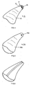
- 7 (a) to (f) are, based on perspective, schematic representations of sections of the Outer wall 18 of in-ear earmolds, novel ventilation groove profiles shown in sections.
- 7 (a) Profile of the ventilation groove 20a rectangular or square with specified, precisely maintained dimensioning ratios.
- 7 (b) is the profile of Ventilation groove 20b circular or elliptical sector-shaped, again with a precisely specified cross-sectional boundary curve 21b.
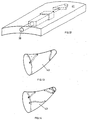
- Cerumen-protected sections can be targeted relevant, exposed parts, as in Fig. 8 at A shown, are provided.
- This training variant of the new ventilation systems is based entirely on at least sections Integrated earmold, against the ear canal wall closed ventilation channels. This system will then based on his training on an earmold shell explained. However, it should be emphasized that if no further aggregates on the considered earmold are integrated and it is designed as a full plastic, the following explanations are of course also true on any channel guide through the mentioned Cover fully plastic.
- 11 are different in analogy to FIG. 7 Cross-sectional shapes and area ratios of the proposed ventilation channels 33a to 33e.
- 11 (a) has in the otoplastic shell 35a built-in ventilation duct 33a rectangular or square Cross-sectional shape.
- 35b has a sector of a circle or an ellipse Channel cross-sectional shape.
- the intended ventilation duct 33c has a circular shape or elliptical cross-sectional shape while at 11 (d) has a triangular design Has cross-sectional shape.
- the Otoplastic shell has a complex internal shape, e.g. a integrated bracket section 37.
- a complex internal shape e.g. a integrated bracket section 37.
- the ventilation duct 35e provided here designed with a cross-sectional shape that is also complex Forms the otoplastic shell uses. Accordingly, it extends its cross-sectional shape partially complicates with that of the Shell 35e attached bracket 37.
- FIG. 12 shows an embodiment variant of a fully integrated ventilation duct 39 shown, the along its length, as shown for example in the otoplastic shell 41, different Cross-sectional shapes and / or cross-sectional dimensions has, which in the sense of realizing different acoustic impedance elements the acoustic Transmission behavior can be optimized.
- this Connection and to the following section 5) referring, it can also be pointed out that because of the possibility of complex acoustic impedance ratios to realize ventilation ducts, especially those in closed construction shown in this section, at least in sections at the same time as acoustic conductor sections more active on the output side electromechanical converter, as on the output side of Microphones, for example in in-the-ear hearing aids, can be exploited.
- FIGS. 9 and 10 is analogous to FIGS. 9 and 10 shown as on the one hand on the respective otoplastic 43 those integrated in this section Ventilation ducts extended by appropriate web guidance or on the other hand like two or more of the channels mentioned, possibly with different and / or varying Channel cross sections, in analogy to Fig. 12, on the Otoplasty can be integrated.
- FIG. 15 schematically shows a longitudinal section reproduced an in-ear otoplastic, in Fig. 16 one schematic cross-sectional representation of a. section this earmold.
- the earmold - e.g. to record electronic components - has a shell 45 which stocking-like, thin-walled made of elastic material.
- the dimensional stability of the - in the illustrated Embodiment smooth outside - shell skin becomes - where desired - by integrally placed on the inside of the bowl Ribs 47 which, with respect to the skin of the shell, are made of the same material.
- 17 is in the form of a perspective illustration purely for example the formation of the outer skin 45 Ribs 47 with varying cross-sectional areas along their longitudinal extent is shown schematically.
- FIG. 20 A such otoplastic is in a cross-sectional view shown schematically in Fig. 20.
- the interior 53 for example from extremely compressible Absorbent material manufactured and from a shaping Skin shell 55 surrounded with the rib pattern 57 "skin" 55 and the rib pattern 57 are common manufactured integrally.
- this is suitable Manufacturing processes explained at the beginning with the help additive construction process. How far in the near future this additive build-up processes, alternating the processed ones Materials can be realized on a workpiece, remain undecided. If this becomes possible, the train is free, for example using the exemplary embodiment according to FIG. 20 also the filler 53 at the same time as the shell skin 55 and the ribs 57 sequentially in respective structural layers build.
- FIGS. 18 and 19 can be seen that with the help of the outer rib pattern at the same time ventilation channels or free spaces are formed can be, as this is purely schematic and for example is represented by the path P.
- otoplastics can also be created, which probably leave a cavity for units to be accommodated, such as electronic components, but in which the space between such a cavity 59 is specific to the necessary volumes and shapes of the additional designed units to be installed and the shell skin 55 is filled, for example, by a resilient or sound-absorbing material or components to be installed are poured out with such a material as far as the shell skin 55.
- the shell skin 55 or 45 can be made of electrically conductive material be made, with which an electrical Shielding effect for internal electronic components is created. This may also apply to the filling 53 20.
- Example of an in-ear earmold shown its shell shape stabilized with internal and / or external ribs is what an extraordinarily light and specifically formable Construction results.
- this type of construction if necessary also with outer ear earmolds be used.
- FIG. 21 shows a further embodiment variant of an in-ear earmold shown which are targeted in one area is bendable or compressible.
- the shell 61 of an otoplastic as in particular the shell of an in-the-ear hearing device for this purpose in one or more specified areas Shaft or corrugated hose formation 63 on what they according to the respective needs, bending or is compressible.
- FIG. 21 shows this procedure using the Represents shell of an in-ear earmold, this can be Procedure and if necessary also for one Realize outer ear otoplastic. Again, this becomes preferably the above Manufacturing process used.
- the inner volume of the Otoplasty with the corresponding requirements Filling material can be filled or integrated into it Internals are embedded in such filler material, which results in a higher stability of the device and improved acoustic conditions.
- an in-ear earmold 65 is schematic and in Longitudinal section shown what the shape of the interior 67 substantially the shape of that shown in Fig. 23 schematically illustrated electronics module 69 to be accommodated equivalent.
- the earmold 65 is made of rubber-elastic Material and can, as shown in Fig. 23, over the Electronics module 69 are slipped.
- the formation of the Interior 67 is such that the or possibly the through several modules to be included directly the earmold 65 can be positioned and held. Because of this, it is easy to get one and the same electronics modules 69 with different To provide earmolds 65, for example in one adolescent child of the changing Ear canal training.
- the earmold will for the in-the-ear hearing aid practically easy interchangeable disposable accessory. Not just to yourself changing conditions in the application area, namely the Ear canal to take account of it, but also simply out Pollution reasons, the earmold 65 can easily change. This concept can even do that be used, if necessary - for example at Ear canal infections - medical applications, for example by applying medication to the Otoplastic outer surface or at least to in Regularly sterilized earmolds use.
- the phase plate 1 otherwise provided in conventional in-the-ear hearing aids is built integrally with the otoplastic.
- the layer-by-layer build-up method described in section 1) is implemented, as shown by dash-dotted lines in FIG. 22 and in the direction indicated by the arrow AB, then it should be possible without further ado, the earmold in the mentioned build-up direction AB depending on the requirements to be made in the respective areas from different materials.
- This also applies to the earmoulds described in sections 2) and 3) and to those explained in the following sections 5), 6) and 7).
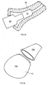
- FIG. 24 is another embodiment of a Otoplasty, again as an example using an in-the-ear hearing aid, shown, which is a simple, quick Replacing the internal fittings allows.
- an in-ear earmold Built-in multi-part and the earmold shell to be designed to be assembled, as shown in FIG. 24.
- fast-acting closures such as snap locks, Latches or even bayonet-like Closures are made possible on the in-ear earmold Separate housing parts 73a and 73b quickly, the Remove internals such as electronic modules and them reinstall in a new shell, possibly with a different one External shaping or basically in a new bowl, too if, for example, for reasons of reprimand, Sterility reasons etc.
- acoustic / electrical transducers or electro-acoustic output converter input or on the output side via assembled as independent parts acoustic conductors, namely tube-like structures with to couple the surroundings of the hearing aid, or else, especially with acoustic / electrical input Transducers, these with their receiving area directly in the To place areas of the surfaces of the hearing aid, if necessary only by slight voids and Protective measures separated from the environment.
- On Converter module 75 has an acoustic input and output 77 on.
- This concept allows to move along the Hearing aid offset and where desired acoustic Provide input openings 85, these in the Otoplastics or their shell 87 integrated acoustic Head 89 to the intended acoustic / electrical To couple converter 91, essentially regardless of where these transducers 91 are installed in the hearing aid. So is in Fig. 26 only shows two converters as an example centralize a module and connect its inputs with the desired receiving openings 85 through the aforementioned guide to connect the acoustic conductor 89.
- each one is individual for their adapted to each carrier. Therefore it would be extremely desirable, every manufactured earmold, as mentioned especially any in-the-ear earmould, especially so to mark each in-the-ear hearing aid. It will therefore proposed into or into the otoplastic Shell, by indentations and / or by bulges one to provide individual labeling, which in addition to the individual customer - e.g. Manufacturer - Product serial number, left-right application etc. included. can. Such labeling is much more preferred Way of manufacturing the earmold with the removal process described under 1). So that will ensures that any confusion from manufacturing the earmold is excluded. Particularly important this is the case with the following, possibly automated Assembly with other modules, such as the Assembly of in-the-ear hearing aids.
- the data registered in the storage unit 95 then fed to a computing unit 97.
- the computing unit 97 controls the output side Manufacturing process 99 for otoplastic.
- the computing unit calculates 97 from the dynamic data stored in the storage unit 95 and possibly, as shown schematically at K, further Manufacturing parameters, the best fit for the Otoplastic, thus optimal comfort in everyday life is achieved while maintaining its functionality.
- the computing unit 97 determines which otoplastic areas are to be designed and how in terms of their flexibility, flexibility, compressibility etc.
- the processor controls the output side 97 the manufacturing process 99, preferably the Manufacturing process as preferred in section 1) Process has been outlined.
Landscapes
- Engineering & Computer Science (AREA)
- Manufacturing & Machinery (AREA)
- Health & Medical Sciences (AREA)
- General Health & Medical Sciences (AREA)
- Neurosurgery (AREA)
- Otolaryngology (AREA)
- Physics & Mathematics (AREA)
- Acoustics & Sound (AREA)
- Signal Processing (AREA)
Priority Applications (1)
| Application Number | Priority Date | Filing Date | Title |
|---|---|---|---|
| EP04017958A EP1555851A3 (fr) | 2000-06-30 | 2000-09-25 | Procédé de fabrication d'otoplastiques et otoplastique correspondant |
Applications Claiming Priority (3)
| Application Number | Priority Date | Filing Date | Title |
|---|---|---|---|
| PCT/CH2000/000356 WO2002003756A1 (fr) | 2000-06-30 | 2000-06-30 | Procede de fabrication d'appareils auditifs et appareil auditif y relatif |
| WOPCT/CH00/00356 | 2000-06-30 | ||
| EP00960273A EP1295509B1 (fr) | 2000-06-30 | 2000-09-25 | Procede de fabrication d'otoplastiques et otoplastique y relatif |
Related Parent Applications (1)
| Application Number | Title | Priority Date | Filing Date |
|---|---|---|---|
| EP00960273A Division EP1295509B1 (fr) | 2000-06-30 | 2000-09-25 | Procede de fabrication d'otoplastiques et otoplastique y relatif |
Related Child Applications (1)
| Application Number | Title | Priority Date | Filing Date |
|---|---|---|---|
| EP04017958A Division EP1555851A3 (fr) | 2000-06-30 | 2000-09-25 | Procédé de fabrication d'otoplastiques et otoplastique correspondant |
Publications (2)
| Publication Number | Publication Date |
|---|---|
| EP1427251A2 true EP1427251A2 (fr) | 2004-06-09 |
| EP1427251A3 EP1427251A3 (fr) | 2006-08-16 |
Family
ID=4358099
Family Applications (4)
| Application Number | Title | Priority Date | Filing Date |
|---|---|---|---|
| EP00938437A Expired - Lifetime EP1295508B1 (fr) | 2000-06-30 | 2000-06-30 | Procede de fabrication d'appareils auditifs et appareil auditif y relatif |
| EP00960273A Expired - Lifetime EP1295509B1 (fr) | 2000-06-30 | 2000-09-25 | Procede de fabrication d'otoplastiques et otoplastique y relatif |
| EP04004629A Withdrawn EP1427251A3 (fr) | 2000-06-30 | 2000-09-25 | Procédé de fabrication d' otoplastiques et otoplastique correspondant |
| EP04017958A Withdrawn EP1555851A3 (fr) | 2000-06-30 | 2000-09-25 | Procédé de fabrication d'otoplastiques et otoplastique correspondant |
Family Applications Before (2)
| Application Number | Title | Priority Date | Filing Date |
|---|---|---|---|
| EP00938437A Expired - Lifetime EP1295508B1 (fr) | 2000-06-30 | 2000-06-30 | Procede de fabrication d'appareils auditifs et appareil auditif y relatif |
| EP00960273A Expired - Lifetime EP1295509B1 (fr) | 2000-06-30 | 2000-09-25 | Procede de fabrication d'otoplastiques et otoplastique y relatif |
Family Applications After (1)
| Application Number | Title | Priority Date | Filing Date |
|---|---|---|---|
| EP04017958A Withdrawn EP1555851A3 (fr) | 2000-06-30 | 2000-09-25 | Procédé de fabrication d'otoplastiques et otoplastique correspondant |
Country Status (8)
| Country | Link |
|---|---|
| EP (4) | EP1295508B1 (fr) |
| JP (2) | JP2004502392A (fr) |
| CN (1) | CN100477815C (fr) |
| AU (4) | AU2000253848B2 (fr) |
| CA (2) | CA2412481C (fr) |
| DE (2) | DE50010130D1 (fr) |
| DK (1) | DK1295509T3 (fr) |
| WO (2) | WO2002003756A1 (fr) |
Cited By (2)
| Publication number | Priority date | Publication date | Assignee | Title |
|---|---|---|---|---|
| EP2615854A1 (fr) | 2012-06-14 | 2013-07-17 | Oticon A/s | Boîtier pour prothèse auditive |
| EP3451704A1 (fr) * | 2017-08-30 | 2019-03-06 | GN Hearing A/S | Écouteur avec microphone de canal, microphone ambiant et récepteur |
Families Citing this family (36)
| Publication number | Priority date | Publication date | Assignee | Title |
|---|---|---|---|---|
| US6540045B1 (en) | 2000-06-30 | 2003-04-01 | Phonak Ag | Method for manufacturing an ear device and ear device |
| DE50010130D1 (de) * | 2000-06-30 | 2005-05-25 | Phonak Ag Staefa | Verfahren zur herstellung von im-ohr-hörgeräten und im-ohr-hörgerät |
| US7014010B2 (en) * | 2000-06-30 | 2006-03-21 | Phonak Ag | Method for manufacturing an ear device and ear device |
| US7625335B2 (en) | 2000-08-25 | 2009-12-01 | 3Shape Aps | Method and apparatus for three-dimensional optical scanning of interior surfaces |
| WO2002024128A1 (fr) * | 2000-09-25 | 2002-03-28 | Phonak Ag | Prothese auditive intra-auriculaire |
| US7050876B1 (en) | 2000-10-06 | 2006-05-23 | Phonak Ltd. | Manufacturing methods and systems for rapid production of hearing-aid shells |
| ES2378060T3 (es) | 2001-03-02 | 2012-04-04 | 3Shape A/S | Procedimiento para modelar piezas auriculares personalizadas |
| EP1246506A1 (fr) | 2001-03-26 | 2002-10-02 | Widex A/S | Système CAD-CAM pour préparer une prothèse auditive |
| EP1246507A1 (fr) * | 2001-03-26 | 2002-10-02 | Widex A/S | Prothèse auditive avec anneau d' étanchéité |
| EP1246505A1 (fr) * | 2001-03-26 | 2002-10-02 | Widex A/S | Prothèse auditive avec plaque frontale qui est produite automatiquement pour s'adapter à la coquille de la prothèse |
| US6660208B2 (en) * | 2001-03-30 | 2003-12-09 | 3D Systems, Inc. | Detoxification of solid freeform fabrication materials |
| EP1257151A3 (fr) * | 2001-05-08 | 2004-01-14 | Dr. Vossieck GmbH | Aide-ouie aéré |
| US7191029B2 (en) * | 2001-06-22 | 2007-03-13 | Siemens Hearing Instruments, Inc. | Rapid prototype fabrication of a monolithic hearing instrument housing with an integrally-fabricated faceplate |
| AU2001278342B2 (en) | 2001-07-26 | 2007-10-18 | Phonak Ag | Method for manufacturing hearing devices |
| AU2008201247B2 (en) * | 2001-10-17 | 2009-11-05 | Phonak Ag | Apparatus and Method for Applying a Substance to a Human Body |
| DE10204894A1 (de) | 2002-02-06 | 2003-08-21 | Siemens Audiologische Technik | Im Ohr tragbares Hörhilfegerät oder Hörhilfegerät mit im Ohr tragbarer Otoplastik |
| JP2005131050A (ja) * | 2003-10-29 | 2005-05-26 | Matsushita Electric Ind Co Ltd | 外耳道形状の測定方法及び補聴器シェルの製造方法並びに補聴器 |
| US7162323B2 (en) | 2004-04-05 | 2007-01-09 | Hearing Aid Express, Inc. | Decentralized method for manufacturing hearing aid devices |
| EP1674060A1 (fr) * | 2004-12-23 | 2006-06-28 | Phonak Ag | Méthode pour fournir un bouchon de protection auditive |
| DE102005020118B3 (de) | 2005-04-29 | 2006-08-31 | Bernhard Kubicke | Gehäuse für ein HdO-Hörgerät |
| CA2613507C (fr) * | 2005-06-27 | 2011-03-15 | Widex A/S | Methode et outil de mise en forme d'une piece allongee deformable destinee a une prothese auditive |
| US7720243B2 (en) | 2006-10-12 | 2010-05-18 | Synygis, Llc | Acoustic enhancement for behind the ear communication devices |
| EP2914019B1 (fr) | 2008-12-22 | 2017-09-13 | Oticon A/s | Un système de prothèse auditive à électrodes |
| US20100226502A1 (en) | 2009-03-06 | 2010-09-09 | Siemens Hearing Instruments, Inc. | Method For Fabricating A Hearing Device |
| DE102009043597A1 (de) * | 2009-09-25 | 2011-04-07 | Siemens Aktiengesellschaft | Verfahren zum Herstellen eines markierten Gegenstandes |
| EP2581038B1 (fr) | 2011-10-14 | 2017-12-13 | Oticon A/S | Appareil auditif automatique en temps réel basé sur des potentiels auditifs évoqués |
| US20140166388A1 (en) * | 2012-12-17 | 2014-06-19 | Cotron Corporation | Ear tip |
| CN105408095A (zh) * | 2013-06-24 | 2016-03-16 | 哈佛学院院长等 | 打印的三维(3d)功能部件及其制造方法 |
| EP2950555A1 (fr) | 2014-05-28 | 2015-12-02 | Oticon A/s | Adaptation d'une prothèse auditive automatique en temps réel sur la base des potentiels auditifs évoqués par des signaux acoustiques naturel |
| DE102014216086A1 (de) * | 2014-08-13 | 2016-02-18 | Sivantos Pte. Ltd. | Vorrichtung und Verfahren zur Integration von Hörgerätekomponenten |
| WO2016037634A1 (fr) * | 2014-09-08 | 2016-03-17 | Sonova Ag | Procédé de production d'une coque de prothèse auditive, coque de prothèse auditive et prothèse auditive |
| WO2017074200A1 (fr) * | 2015-10-30 | 2017-05-04 | Transverse Technology Limited | Enceinte pour haut-parleur audio |
| CN108055632B (zh) * | 2018-02-11 | 2020-05-26 | 佛山博智医疗科技有限公司 | 耳道形态模化制作装置和方法 |
| CN109848414B (zh) * | 2019-01-31 | 2021-02-02 | 攀枝花三帝科技有限公司 | 一种3d打印定制化助听器的制作方法 |
| EP3706440A1 (fr) * | 2019-03-08 | 2020-09-09 | GN Hearing A/S | Dispositif d'aide auditive avec évent |
| EP4018935A1 (fr) * | 2020-12-23 | 2022-06-29 | Sonova AG | Procédé de détermination d'une géométrie d'un canal auriculaire ou d'une partie de l'oreille d'une personne |
Family Cites Families (17)
| Publication number | Priority date | Publication date | Assignee | Title |
|---|---|---|---|---|
| GB191308960A (en) * | 1913-04-16 | 1914-02-12 | Hermann Nieriker | Improvements in and relating to Means for Protecting the Human Ear against Objectionable Noises and the like. |
| US4194512A (en) * | 1977-06-08 | 1980-03-25 | Foti Thomas M | Probe for nystagmus testing |
| DE8518681U1 (de) * | 1985-06-27 | 1986-06-12 | Siemens AG, 1000 Berlin und 8000 München | Hörhilfe |
| JPS6232800A (ja) * | 1985-08-06 | 1987-02-12 | Rion Co Ltd | 補聴器用耳型の製作方法 |
| US5068902A (en) * | 1986-11-13 | 1991-11-26 | Epic Corporation | Method and apparatus for reducing acoustical distortion |
| DE8816266U1 (de) * | 1988-01-19 | 1989-04-13 | Siemens AG, 1000 Berlin und 8000 München | Ohreinsatz für Hörgeräte, insbesondere Otoplastik für In-dem-Ohr-Hörgeräte und Ohrpaßstück für Hinter-dem-Ohr-Hörgeräte |
| CH677570A5 (fr) * | 1989-05-17 | 1991-05-31 | Ascom Audiosys Ag | |
| DE58909119D1 (de) * | 1989-07-26 | 1995-04-20 | Siemens Audiologische Technik | Verfahren und Vorrichtung zur Herstellung einer Gehäuseschale eines In-dem-Ohr-Hörgerätes sowie nach dem Verfahren hergestellte Gehäuseschale. |
| EP0451784A3 (en) * | 1990-04-12 | 1991-11-13 | Beltone Electronics Corporation | Modular hearing aid system |
| US5487012A (en) * | 1990-12-21 | 1996-01-23 | Topholm & Westermann Aps | Method of preparing an otoplasty or adaptive earpiece individually matched to the shape of an auditory canal |
| DE19525865A1 (de) * | 1995-07-15 | 1997-01-16 | Sennheiser Electronic | Hörhilfe mit einem elektrodynamischen Schallwandler |
| JPH0966021A (ja) * | 1995-08-31 | 1997-03-11 | Toshiba Corp | 内視鏡 |
| JP2837649B2 (ja) * | 1995-10-04 | 1998-12-16 | リオン株式会社 | 挿耳形補聴器用シェルの製造方法 |
| BE1010200A3 (nl) * | 1996-04-26 | 1998-03-03 | Variphone Benelux Naamloze Ven | Werkwijze en inrichting voor het vervaardigen van oorstukjes. |
| DE19727677A1 (de) * | 1997-06-30 | 1999-01-07 | Huels Chemische Werke Ag | Verfahren und Vorrichtung zur Herstellung von dreidimensionalen Objekten |
| WO2000034739A2 (fr) * | 1998-12-10 | 2000-06-15 | William Forrest Fagan | Procede de fabrication d'enveloppes d'appareils de correction auditive |
| DE50010130D1 (de) * | 2000-06-30 | 2005-05-25 | Phonak Ag Staefa | Verfahren zur herstellung von im-ohr-hörgeräten und im-ohr-hörgerät |
-
2000
- 2000-06-30 DE DE50010130T patent/DE50010130D1/de not_active Expired - Lifetime
- 2000-06-30 AU AU2000253848A patent/AU2000253848B2/en not_active Expired
- 2000-06-30 EP EP00938437A patent/EP1295508B1/fr not_active Expired - Lifetime
- 2000-06-30 JP JP2002507028A patent/JP2004502392A/ja active Pending
- 2000-06-30 AU AU5384800A patent/AU5384800A/xx active Pending
- 2000-06-30 CN CNB008195552A patent/CN100477815C/zh not_active Expired - Lifetime
- 2000-06-30 WO PCT/CH2000/000356 patent/WO2002003756A1/fr not_active Ceased
- 2000-06-30 CA CA2412481A patent/CA2412481C/fr not_active Expired - Lifetime
- 2000-09-25 DK DK00960273T patent/DK1295509T3/da active
- 2000-09-25 CA CA002412934A patent/CA2412934C/fr not_active Expired - Lifetime
- 2000-09-25 JP JP2001510287A patent/JP2003534826A/ja active Pending
- 2000-09-25 DE DE50006193T patent/DE50006193D1/de not_active Expired - Lifetime
- 2000-09-25 AU AU7265400A patent/AU7265400A/xx active Pending
- 2000-09-25 EP EP00960273A patent/EP1295509B1/fr not_active Expired - Lifetime
- 2000-09-25 WO PCT/CH2000/000519 patent/WO2001005207A2/fr not_active Ceased
- 2000-09-25 AU AU2000272654A patent/AU2000272654B9/en not_active Expired
- 2000-09-25 EP EP04004629A patent/EP1427251A3/fr not_active Withdrawn
- 2000-09-25 EP EP04017958A patent/EP1555851A3/fr not_active Withdrawn
Non-Patent Citations (1)
| Title |
|---|
| None * |
Cited By (5)
| Publication number | Priority date | Publication date | Assignee | Title |
|---|---|---|---|---|
| EP2615854A1 (fr) | 2012-06-14 | 2013-07-17 | Oticon A/s | Boîtier pour prothèse auditive |
| EP3451704A1 (fr) * | 2017-08-30 | 2019-03-06 | GN Hearing A/S | Écouteur avec microphone de canal, microphone ambiant et récepteur |
| US11026030B2 (en) | 2017-08-30 | 2021-06-01 | Gn Hearing A/S | Earpiece with canal microphone, ambient microphone and receiver |
| US11882408B2 (en) | 2017-08-30 | 2024-01-23 | Gn Hearing A/S | Earpiece with canal microphone, ambient microphone and receiver |
| US12369002B2 (en) | 2017-08-30 | 2025-07-22 | Gn Hearing A/S | Earpiece with canal microphone, ambient microphone and receiver |
Also Published As
| Publication number | Publication date |
|---|---|
| AU7265400A (en) | 2001-02-05 |
| JP2003534826A (ja) | 2003-11-25 |
| DK1295509T3 (da) | 2004-08-16 |
| JP2004502392A (ja) | 2004-01-22 |
| WO2001005207A3 (fr) | 2001-12-06 |
| EP1295509B1 (fr) | 2004-04-21 |
| CN100477815C (zh) | 2009-04-08 |
| DE50010130D1 (de) | 2005-05-25 |
| CA2412934C (fr) | 2009-10-27 |
| EP1555851A3 (fr) | 2006-08-16 |
| CN1461578A (zh) | 2003-12-10 |
| EP1295509A2 (fr) | 2003-03-26 |
| WO2001005207A2 (fr) | 2001-01-25 |
| EP1295508B1 (fr) | 2005-04-20 |
| AU2000253848A1 (en) | 2002-04-11 |
| EP1295508A1 (fr) | 2003-03-26 |
| EP1427251A3 (fr) | 2006-08-16 |
| EP1555851A2 (fr) | 2005-07-20 |
| CA2412481A1 (fr) | 2002-12-05 |
| AU2000253848B2 (en) | 2006-04-06 |
| AU5384800A (en) | 2002-01-14 |
| AU2000272654B9 (en) | 2006-08-03 |
| AU2000272654B2 (en) | 2006-01-12 |
| CA2412934A1 (fr) | 2001-01-25 |
| WO2002003756A1 (fr) | 2002-01-10 |
| DE50006193D1 (de) | 2004-05-27 |
| CA2412481C (fr) | 2010-04-13 |
Similar Documents
| Publication | Publication Date | Title |
|---|---|---|
| EP1295509B1 (fr) | Procede de fabrication d'otoplastiques et otoplastique y relatif | |
| EP1320339B1 (fr) | Otoplastique et procede de fabrication d'un otoplastique | |
| US6863151B2 (en) | Method for manufacturing an ear device and ear device | |
| EP2986032B1 (fr) | Dispositif et procede d'integration de composants d'appareil auditif | |
| AU2002300247B2 (en) | Method for manufacturing an ear device and ear device | |
| EP1463375B1 (fr) | Prothèse auditive pour l'oreille externe avec un moulage auriculaire | |
| EP1323331B1 (fr) | Procede de production d'otoplastiques | |
| EP1320341B1 (fr) | Otoplastique | |
| WO2002024128A1 (fr) | Prothese auditive intra-auriculaire | |
| EP1321011B1 (fr) | Otoplastique avec module integre, otoplastique place dans l'oreille et procede d'adaptation des otoplastiques | |
| DE102009009286B4 (de) | Hörvorrichtung mit individuell ausgerichteter Elektronikkomponente und Herstellungsverfahren | |
| DE102009016483A1 (de) | Verfahren zum Herstellen eines Gehäuseteils eines Hörgeräts und entsprechendes Gehäuseteil | |
| DE202004011467U1 (de) | Gehörgangsplastik für Hinter-dem-Ohr-Hörgeräte | |
| AU2008201247A1 (en) | Apparatus and Method for Applying a Substance to a Human Body |
Legal Events
| Date | Code | Title | Description |
|---|---|---|---|
| PUAI | Public reference made under article 153(3) epc to a published international application that has entered the european phase |
Free format text: ORIGINAL CODE: 0009012 |
|
| AC | Divisional application: reference to earlier application |
Ref document number: 1295509 Country of ref document: EP Kind code of ref document: P |
|
| AK | Designated contracting states |
Kind code of ref document: A2 Designated state(s): CH DE DK FR GB IT LI |
|
| PUAL | Search report despatched |
Free format text: ORIGINAL CODE: 0009013 |
|
| AK | Designated contracting states |
Kind code of ref document: A3 Designated state(s): CH DE DK FR GB IT LI |
|
| 17P | Request for examination filed |
Effective date: 20061118 |
|
| AKX | Designation fees paid |
Designated state(s): CH DE DK FR GB LI |
|
| RAP1 | Party data changed (applicant data changed or rights of an application transferred) |
Owner name: SONOVA AG |
|
| 17Q | First examination report despatched |
Effective date: 20170413 |
|
| STAA | Information on the status of an ep patent application or granted ep patent |
Free format text: STATUS: THE APPLICATION IS DEEMED TO BE WITHDRAWN |
|
| 18D | Application deemed to be withdrawn |
Effective date: 20170824 |
|
| RIC1 | Information provided on ipc code assigned before grant |
Ipc: H04R 25/00 20060101AFI20040406BHEP |