EP1555851A2 - Procédé de fabrication d'otoplastiques et otoplastique correspondant - Google Patents
Procédé de fabrication d'otoplastiques et otoplastique correspondant Download PDFInfo
- Publication number
- EP1555851A2 EP1555851A2 EP04017958A EP04017958A EP1555851A2 EP 1555851 A2 EP1555851 A2 EP 1555851A2 EP 04017958 A EP04017958 A EP 04017958A EP 04017958 A EP04017958 A EP 04017958A EP 1555851 A2 EP1555851 A2 EP 1555851A2
- Authority
- EP
- European Patent Office
- Prior art keywords
- earmold
- ear
- shell
- hearing aid
- individual
- Prior art date
- Legal status (The legal status is an assumption and is not a legal conclusion. Google has not performed a legal analysis and makes no representation as to the accuracy of the status listed.)
- Withdrawn
Links
Images



Classifications
-
- H—ELECTRICITY
- H04—ELECTRIC COMMUNICATION TECHNIQUE
- H04R—LOUDSPEAKERS, MICROPHONES, GRAMOPHONE PICK-UPS OR LIKE ACOUSTIC ELECTROMECHANICAL TRANSDUCERS; ELECTRIC HEARING AIDS; PUBLIC ADDRESS SYSTEMS
- H04R25/00—Electric hearing aids
- H04R25/65—Housing parts, e.g. shells, tips or moulds, or their manufacture
- H04R25/652—Ear tips; Ear moulds
-
- H—ELECTRICITY
- H04—ELECTRIC COMMUNICATION TECHNIQUE
- H04R—LOUDSPEAKERS, MICROPHONES, GRAMOPHONE PICK-UPS OR LIKE ACOUSTIC ELECTROMECHANICAL TRANSDUCERS; ELECTRIC HEARING AIDS; PUBLIC ADDRESS SYSTEMS
- H04R25/00—Electric hearing aids
- H04R25/65—Housing parts, e.g. shells, tips or moulds, or their manufacture
- H04R25/658—Manufacture of housing parts
-
- B—PERFORMING OPERATIONS; TRANSPORTING
- B29—WORKING OF PLASTICS; WORKING OF SUBSTANCES IN A PLASTIC STATE IN GENERAL
- B29C—SHAPING OR JOINING OF PLASTICS; SHAPING OF MATERIAL IN A PLASTIC STATE, NOT OTHERWISE PROVIDED FOR; AFTER-TREATMENT OF THE SHAPED PRODUCTS, e.g. REPAIRING
- B29C64/00—Additive manufacturing, i.e. manufacturing of three-dimensional [3D] objects by additive deposition, additive agglomeration or additive layering, e.g. by 3D printing, stereolithography or selective laser sintering
- B29C64/10—Processes of additive manufacturing
-
- B—PERFORMING OPERATIONS; TRANSPORTING
- B33—ADDITIVE MANUFACTURING TECHNOLOGY
- B33Y—ADDITIVE MANUFACTURING, i.e. MANUFACTURING OF THREE-DIMENSIONAL [3D] OBJECTS BY ADDITIVE DEPOSITION, ADDITIVE AGGLOMERATION OR ADDITIVE LAYERING, e.g. BY 3D PRINTING, STEREOLITHOGRAPHY OR SELECTIVE LASER SINTERING
- B33Y80/00—Products made by additive manufacturing
-
- H—ELECTRICITY
- H04—ELECTRIC COMMUNICATION TECHNIQUE
- H04R—LOUDSPEAKERS, MICROPHONES, GRAMOPHONE PICK-UPS OR LIKE ACOUSTIC ELECTROMECHANICAL TRANSDUCERS; ELECTRIC HEARING AIDS; PUBLIC ADDRESS SYSTEMS
- H04R2225/00—Details of deaf aids covered by H04R25/00, not provided for in any of its subgroups
- H04R2225/025—In the ear hearing aids [ITE] hearing aids
-
- H—ELECTRICITY
- H04—ELECTRIC COMMUNICATION TECHNIQUE
- H04R—LOUDSPEAKERS, MICROPHONES, GRAMOPHONE PICK-UPS OR LIKE ACOUSTIC ELECTROMECHANICAL TRANSDUCERS; ELECTRIC HEARING AIDS; PUBLIC ADDRESS SYSTEMS
- H04R2225/00—Details of deaf aids covered by H04R25/00, not provided for in any of its subgroups
- H04R2225/77—Design aspects, e.g. CAD, of hearing aid tips, moulds or housings
Definitions
- the present invention relates to a method according to the preamble of claim 1 and an earmold according to that of claim 7.
- the present invention is based on problems that arise in the manufacture of in-ear hearing aids to have.
- the solution found in this regard can generally be applied to earmolds, to their definition is pointed out below.
- This form is then sent to the hearing aid manufacturer, where, based on this form, the Hearing aid shell is cast from a plastic.
- the described procedure is on the one hand extremely labor-intensive, and the resulting hearing aid remains of its wearing comfort as well as from the space use her considered mostly suboptimal.
- the mentioned in the conventional Materials used in manufacturing processes also require a relatively high wall thickness of the in-ear hearing aid shell, which further the space available for the mentioned functional parts, than this anyway Case is reduced.
- the present invention aims to remedy these drawbacks mentioned.
- she draws is characterized by the fact that the at least one shape is digitized three-dimensionally to a record and the earmold or whose shell is created by an additive construction process, controlled by the record.
- this manufacturing method is particularly suitable for in-the-ear hearing aids, it can with similar benefits also for external ear hearing aids, continue to be used for other earmolds, as for the production of headphones of all kinds, of water protection inserts, noise protection inserts, etc.
- the method is taken into account that the field of application of earmolds - it is especially on in-ear otoplastics pointed out - in everyday life is subjected to great dynamics, such as the ear canal by chewing movements.
- great dynamics such as the ear canal by chewing movements.
- an earmold to be a device that is immediately outside the pinna and / or is applied to the auricle and / or in the ear canal.
- These include external ear hearing aids, in-the-ear hearing aids, Headphones, noise protection and water protection inserts etc.
- a thin layer of material is deposited on a surface This is like the laser sintering or the stereolithography still over the entire surface, be it like the thermojet process already in the contour of a section of the earpiece under construction or its shell. thereupon The desired sectional shape is stabilized or solidified.
- a new layer is deposited as described above and this in turn solidified and connected to the underlying, already finished layer. So layer by layer becomes the Otoplasty or its shell created by additive layer-by-layer application.
- For industrial production is preferably not only the cut layer for an individual Otoplastic or its shell stored or solidified, but at the same time several each individual.
- At laser sinter solidifies e.g. one laser, usually mirror-controlled, one behind the other the slice layers of several earmolds or their shells, before all solidified cut layers are lowered together. Thereupon, after Laying a new layer of powder over all already solidified and lowered cutting layers, in turn the formation of the several further cut layers.
- the respective earmolds or their shells digitally controlled, individually manufactured.
- either a single laser beam is used for solidifying the plurality of slice layers and / or More than one beam is operated and controlled in parallel.
- An alternative to this procedure is to solidify a slice with a laser at a time, while at the same time the powder layer is deposited for the formation of a further earmold or earmold shell. Thereafter, the same laser becomes the prepared powder layer corresponding to the cut layer for the further plastic solidify while the previously solidified layer is lowered and there a new powder layer is deposited.
- the Laser then works intermittently between two or more earmolds or earmold shells wherein the laser insert dead time resulting from the powder deposition during the formation of one of the shells for the Solidification of a cut layer of another earmold under construction is exploited.
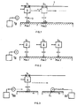
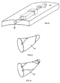
- Fig. 1 is shown schematically how, in a variant, by means of laser sintering or laser or stereolithography several earmolds or their shells are manufactured industrially in a parallel process.
- the laser with control unit 5 and beam 3 is mounted above the material bed 1 for powder or liquid medium.
- position 1 it solidifies the layer S 1 of a first otoplastic or its shell, driven by the first individual data set D 1 .
- a displacement device 7 in a second position, where he creates the layer S 2 according to a further individual contour with the individual record D 2 .
- several of the lasers can be moved as a unit and in each case more than one individual earmold layer can be created simultaneously.
- laser 5 solidifies layer S 1 on a powder bed or liquid bed 1 , and then changes over to bed 1b (dashed line), whereupon, during the solidification phase on bed 1 a, the powder application device 9 b over a previously solidified layer S 1 .
- Powder removes or, in laser or stereolithography, the layer S 1 . is lowered. Only when the laser 5 becomes active at the bed 1b is carried out with the powder dispenser 9a depositing a renewed layer of powder over the just solidified layer S 1 at the bed 1a, or the layer S 1 is done lowering in the fluid bed 1a.
- thermojet method and the analog productivity increase simultaneously cut layers filed by more than one earmold or their shells, practically in a drawing train by a Application header or, in parallel, by several.
- materials for additive construction methods which are to a rubber-elastic and but dimensionally stable shell can be formed, which, if desired, locally different up to extremely thin-walled and still can be realized tear resistant.
- the digitization of the individual application area in particular of the application area for a hearing aid, in particular in-ear hearing aid, in a specialized Institution, in the last-mentioned case with the audiologist.
- the individual form recorded there, as digital 3D information will be transmitted to a production center, in particular in connection with hearing aids, be it by sending a data carrier, be it by Intemettax etc. in the production center is, in particular using the above-mentioned method, the earmold or its shell, considered in the Case ie the in-ear hearing aid shell, individually shaped.
- a production center in particular in connection with hearing aids, be it by sending a data carrier, be it by Intemettax etc.
- the production center is, in particular using the above-mentioned method, the earmold or its shell, considered in the Case ie the in-ear hearing aid shell, individually shaped.
- thermoplastic materials used in general to a relatively elastic, conforming outer shape is also the shaping of pressure points at Otoplastics or their shells far less critical than was previously the case, which is especially for in-ear earmoulds is of crucial importance.
- in-ear earmoulds can be used as hearing protection devices, Headphones, water protection devices, but especially for in-the-ear hearing aids, similar to rubber elastic Grafting be used, and it nestles its surface optimally to the Appllkations Symposium, the auditory canal, on.
- such elements are those with the proposed technique directly in the earmold shell can be installed, for example: holders and holders for components, cerumen protection systems, Ventilation ducts for in-ear earmoulds, supporting elements that support the latter in the ear canal for in-ear earmolds, like so-called claws (English channel locks).
- FIG. 4 shows, for example and schematically, an in-ear earmold 11, for example an in-the-ear hearing device, in which the acoustic output 13 to the eardrum protected by a cerumen cap 15 is.
- This protective cap 15 is until now in the production as a separate part on the shell 16 of the otoplasty eleventh applied and fixed for example by gluing or welding.
- the cerumen protective cap 15a is directly attached to the shell 16a of the otherwise identical in-ear earmold 11a integrated.
- the material of the shell 16a is homogeneous in that of Cerumen cap 15a over.
- cerumen protection systems and other functional elements by use of the mentioned manufacturing process can be integrated integrally.
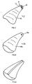
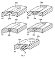
- FIGS. 7 (a) to (f) on the basis of perspective, schematic representations of sections of FIGS Ear canal adjacent outer wall 18 of in-ear earmoulds, novel ventilation grooves sections shown.
- the profile of the ventilation groove 20a is rectangular or square-shaped with predefined, exactly maintained dimensioning conditions.
- the profile of the ventilation groove 20b is circular or Elliptic sector-shaped, again with exactly predetermined cross-sectional boundary curve 21 b.
- the cross-sectional shape of the provided vent grooves 20 may already have some predictability and influencing the acoustic transmission conditions along this groove, in case of contact with the inner wall of the auditory canal, will be realized.
- the acoustic behavior is also dependent on the length, with which extends the groove 20 along the earmold outer wall 18.
- FIGS. 7 (c) to (f) show further ventilation groove profiles which are additionally cerumen-protected are.
- the profile of the groove 20c according to FIG. 7 (c) is T-shaped.
- Fig. 7 (d) to 7 (f) following the illustrated principle of Fig. 7 (c), is the cross-sectional shape of the wide groove portion 27d to 27f formed with different shapes, as shown in FIG. 7 (d) circular sector or according to the sector an ellipse, according to Fig. 7 (e) triangular, according to Fig. 7 (f) circular or elliptical.
- vent grooves 29 for example, according to FIG. 8, which, progressively advancing in their longitudinal direction, define different profiles, as they are optionally made of profiles in FIG are shown compiled according to FIG.
- the groove adjacent to the auditory canal can be mathematically modeled and checked, then into the in-ear earmold or their shell are integrated.
- the intended ventilation grooves form longer than this principle by the longitudinal extent of a considered in the ear otoplasty.
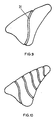
- this is achieved in that such grooves 31 with training, as they are shown with reference to FIGS. 7 and 8, for example, in predetermined curves along the surface of the earmold be performed, for example, as shown in Fig. 9, practically as the earmold thread-like grooves.
- Further optimization flexibility is achieved in that not only a vent groove, but several are guided on the surface of the earmold, as shown schematically in Fig. 10 is.
- the high flexibility of the groove design means that depending on the application area in the ear canal specifically different dimensioned, with respect to cerumen protection and acoustic transmission conditions optimized respectively Ventilation grooves along the earmold surface can be realized.
- This training variant of the novel ventilation systems is based on at least sections completely integrated into the earmold closed against the ear canal ventilation ducts. This system will subsequently explained on the basis of his training on an earmold shell. But it is important to emphasize that then, if no further aggregates are to be integrated on the considered otoplastic and they are designed as a solid plastic is, the following comments, of course, also on a channel guide arbitrarily by the mentioned Obtain full plastic throughout.
- FIG. 11 in analogy to FIG. 7, different cross-sectional shapes and area ratios are proposed Ventilation channels 33a to 33e shown.
- the one incorporated into the otoplastic shell 35a has Ventilation duct 33a Rectangular or square cross-sectional shape.
- the embodiment according to FIG. 11 (b) it has, 35b, a circular sector or elliptical sector-shaped channel cross-sectional shape.
- the embodiment according to Fig. 11 (c) has the intended ventilation channel 33 c circular or elliptical cross-sectional shape
- FIG. 11 (d) has a triangular cross-sectional shape.
- the otoplastic shell has a complex internal shaping, eg. B. an integrated bracket section 37.
- a complex internal shaping eg. B. an integrated bracket section 37.
- FIG. 12 shows a variant of a fully integrated ventilation channel 39.
- the along its longitudinal extent as shown for example in the Otoplastikschale 41, different cross-sectional shapes and / or has cross-sectional dimensions, which in the sense of the realization of different acoustic Impedance elements, the acoustic transmission behavior can be optimized.
- ventilation ducts especially those in this section illustrated closed construction, quite at least in sections simultaneously as acoustic Conductor sections on the output side active electromechanical transducer, such as the output side of microphones, for example in in-the-ear hearing aids, can be exploited.
- FIGS. 13 and 14 show, in analogy to FIGS. 9 and 10, how, on the one hand, the respective earmold 43 extended the integrated ventilation channels explained in this section by appropriate web guide or on the other hand as two and more of the mentioned channels, possibly with different and / or varying channel cross-sections, in analogy to FIG. 12, are integrated at the earmold.
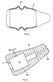
- FIG. 15 schematically shows a longitudinal sectional illustration of an in-ear otoplastic
- FIG. 16 a schematic cross-sectional view of a portion of this earmold.
- the earmold e.g. to record electronic components-has a shell 45, which is stocking-like, thin-walled made of elastic material.
- the dimensional stability of the - outside in the illustrated embodiment smooth - shell skin is - where desired - ensured by attached to the shell integrally inside ribs 47 which, with respect to the shell skin, from the same material are made.
- the course of the wall thickness of shell skin 45 becomes the density and shape of the ribs 47 previously calculated and then the earmold constructed according to the calculated data.
- the above-described manufacturing process using additive construction process extremely well.
- the just described training of the in-ear earmould can be combined with a thoroughly Ventilation system, as explained with reference to FIGS. 7 to 14.
- the provided ribs for influencing the dimensional stability or flexibility in certain areas of the otoplastic also with different Cross-sectional profile are formed, possibly also in its longitudinal extent progressively from a cross section going over to the other.
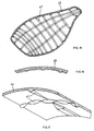
- an outer rib pattern may also be provided. According to FIGS. 18 and 19, for this purpose, if appropriate with regions of different density, orientation and profile shape, on the outer surface of the earmold 49 worked up a pattern of ribs 51.
- this can be used for the otoplastic with cavity considered here, but also for earmolds with no cavity, so for example with no electronic components, e.g. for hearing protection equipment or water protection devices.
- earmold is schematic in a cross-sectional view shown in Fig. 20.
- the interior 53 is made, for example, of extremely compressible absorption material manufactured and surrounded by a shaping skin shell 55 with the rib pattern 57.
- skin 55th and the rib pattern 57 are made integral together.
- the manufacturing method explained above is suitable with the help of additive construction procedures. How far in the near future these additive construction procedures can be realized by changing the processed materials on a workpiece, remain an open question. Should this be possible, the web is free, for example, on the embodiment of FIG. 20 and the filler 53 simultaneously with the shell skin 55 and the ribs 57 in each build-up layers build sequentially.
- earmolds may be provided which are likely to leave a cavity for male assemblies such as electronic components, but in which the space between such a lumen 59 is specific to the necessary volumes and shapes of additional designed units to be installed and the shell skin 55 is filled for example by a spring-loaded or sound-absorbing material or components to be installed with such a material to the shell skin 55 are poured out.
- the shell skin 55 or 45, according to FIGS. 15, 16 and 17, may well be made of electrically conductive material Material be made, which at the same time an electrical shielding effect for internal electronic components is created. This also applies, if necessary, to the filling 53 according to FIG. 20.
- an otoplastic was shown using the example of an in-ear otoplastic, whose Shell with internal and / or external ribs is dimensionally stabilized, which is an extremely light and targeted formable construction results.
- this design can also be used for outer ear earmoulds be used.
- a further embodiment of an in-ear earmold is shown, which specifically in a Range is bendable or compressible.
- the shell 61 of an otoplastic in particular the shell of an in-ear hearing aid, has for this purpose in one or more predetermined areas a corrugated or corrugated hose training 63, to which it is, according to the respective needs, bendable or compressible.
- Fig. 21 this If the procedure is based on the shell of an in-ear otoplastic, this procedure can be completely and if necessary also for an outer ear earmould realize. Again, this is preferably the initially explained Manufacturing process used.
- the internal volume the earmold be filled with the requirements of the corresponding filling material or integrated internals therein be embedded in such filler, resulting in a higher stability of the device results and improved Acoustic conditions.
- the conventional problem is that even if the hearing aid internals could be maintained over long periods of life, for example, only the transmission behavior the hearing aid should be readjusted according to the respective hearing conditions, anyway always new hearing aids have to be designed, just because of the fact that the former no longer fit satisfactorily in the ear canal.
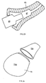
- an in-ear earmold 65 is shown schematically and in longitudinal section, to which the shape of the Inneraumes 67 substantially the shape of the in Fig. 23 schematically illustrated, male electronic module 69 corresponds.
- the earmold 65 is made of rubber-elastic material and can, as shown in Fig. 23, on the Electronics module 69 are slipped.
- the shaping of the interior 67 is such that the or possibly the plurality male modules are positively positioned and held directly by the earmold 65. by virtue of By this procedure, it is easily possible, one and the same electronic modules 69 with different earmolds 65th To provide such as in a growing child, the changing ear canal education Take into account.
- the earmold is practically an easily replaceable disposable accessory for the in-ear hearing aid. Not only to changing conditions in the application area, namely the ear canal, bill To wear, but also simply for reasons of pollution, the otoplasty 65 can be easily changed. This Concept can even be exploited, if necessary - for example, in ear canal inflammation - medical applications for example, by applying medicaments to the earmold outer surface or at least to use sterilized earmolds at regular intervals.
- the phase plate 1 otherwise provided in conventional in-the-ear hearing aids is built as part of the module holder, integrally with the otoplastic.
- the layer-to-layer build-up method set forth in section 1) as in FIG. 22 dash-dotted lines and in the direction indicated by the arrow AB
- the otoplastic in the above-mentioned construction direction AB it would be readily possible for the otoplastic in the above-mentioned construction direction AB to be arranged according to requirements respective areas made of different materials.
- This also applies to the earmolds described in Sections 2) and 3) as well as to those explained in the following sections 5), 6) and 7).
- FIG. 24 shows a further embodiment of an otoplastic, again by way of example with reference to an in-ear hearing device. shown, which allows a simple, rapid replacement of the internal installations. in principle It is proposed, the earmold shell in several parts and assembled on an in-ear earmold with internals form, as shown in FIG. 24.
- acoustic / electrical transducers or electro-acoustic output transducer input and output side assembled over as independent parts acoustic conductors, namely tube-like structures to couple with the environment of the hearing aid, or, in particular in the case of input-side acoustic / electrical converters, these with their recording surface directly in the areas the surfaces of the hearing aid to place, possibly only by small cavities and protective measures separated from the environment.
- a converter module 75 has an acoustic input and output 77 on.
- the shell 79 of the earmold of an in-ear or an outer ear hearing aid or a headphone has, integrated into it, an acoustic conductor 81 on. It is at least partially and as shown in Fig. 25 within the wall of the earmold shell 79.
- acoustic stub lines or line sections 83 preferably the respective acoustic impedance of the acoustic conductor 81 adapted.
- FIG. 26 shows only two centralized transducers to form a module and their entrances to the desired receiving openings 85 through the mentioned guidance of the acoustic To connect conductor 89.
- any manufactured earmold as mentioned in particular to mark each in-ear earmold, especially any in-the-ear hearing aid. It is therefore suggested in the earmold or in the shell, by indentations and / or by bulges an individual Provide identification, which together with the individual customer -. Manufacturer - Product serial number, Left-right application etc. may contain. Such a marking is in a much preferred manner and Made way in the manufacture of the earmold with the removal method described under 1). This will ensure that any confusion of the earmoulds is excluded from the production. This is especially important in the subsequent, possibly automated assembly with other modules, such as the assembly of in-the-ear hearing aids.
- these impressions are scanned and the respective digital data records in the memory unit 95 filed.
- the dynamics of the application area by X-rays be recorded.
- the arithmetic unit 97 controls the manufacturing process 99 for the earmold. For example, and as is customary today, in-ear earmolds are made with relative hard shell, the arithmetic unit 97 calculates from the stored on the memory unit 95 dynamic data and optionally, as shown schematically at K, other manufacturing parameters, the best fit for the earmold, so optimum wearing comfort is achieved in everyday life, while maintaining their functionality.
Landscapes
- Engineering & Computer Science (AREA)
- Manufacturing & Machinery (AREA)
- Health & Medical Sciences (AREA)
- General Health & Medical Sciences (AREA)
- Neurosurgery (AREA)
- Otolaryngology (AREA)
- Physics & Mathematics (AREA)
- Acoustics & Sound (AREA)
- Signal Processing (AREA)
Applications Claiming Priority (4)
| Application Number | Priority Date | Filing Date | Title |
|---|---|---|---|
| PCT/CH2000/000356 WO2002003756A1 (fr) | 2000-06-30 | 2000-06-30 | Procede de fabrication d'appareils auditifs et appareil auditif y relatif |
| WOPCT/CH00/00356 | 2000-06-30 | ||
| EP04004629A EP1427251A3 (fr) | 2000-06-30 | 2000-09-25 | Procédé de fabrication d' otoplastiques et otoplastique correspondant |
| EP00960273A EP1295509B1 (fr) | 2000-06-30 | 2000-09-25 | Procede de fabrication d'otoplastiques et otoplastique y relatif |
Related Parent Applications (1)
| Application Number | Title | Priority Date | Filing Date |
|---|---|---|---|
| EP04004629A Division EP1427251A3 (fr) | 2000-06-30 | 2000-09-25 | Procédé de fabrication d' otoplastiques et otoplastique correspondant |
Publications (2)
| Publication Number | Publication Date |
|---|---|
| EP1555851A2 true EP1555851A2 (fr) | 2005-07-20 |
| EP1555851A3 EP1555851A3 (fr) | 2006-08-16 |
Family
ID=4358099
Family Applications (4)
| Application Number | Title | Priority Date | Filing Date |
|---|---|---|---|
| EP00938437A Expired - Lifetime EP1295508B1 (fr) | 2000-06-30 | 2000-06-30 | Procede de fabrication d'appareils auditifs et appareil auditif y relatif |
| EP00960273A Expired - Lifetime EP1295509B1 (fr) | 2000-06-30 | 2000-09-25 | Procede de fabrication d'otoplastiques et otoplastique y relatif |
| EP04004629A Withdrawn EP1427251A3 (fr) | 2000-06-30 | 2000-09-25 | Procédé de fabrication d' otoplastiques et otoplastique correspondant |
| EP04017958A Withdrawn EP1555851A3 (fr) | 2000-06-30 | 2000-09-25 | Procédé de fabrication d'otoplastiques et otoplastique correspondant |
Family Applications Before (3)
| Application Number | Title | Priority Date | Filing Date |
|---|---|---|---|
| EP00938437A Expired - Lifetime EP1295508B1 (fr) | 2000-06-30 | 2000-06-30 | Procede de fabrication d'appareils auditifs et appareil auditif y relatif |
| EP00960273A Expired - Lifetime EP1295509B1 (fr) | 2000-06-30 | 2000-09-25 | Procede de fabrication d'otoplastiques et otoplastique y relatif |
| EP04004629A Withdrawn EP1427251A3 (fr) | 2000-06-30 | 2000-09-25 | Procédé de fabrication d' otoplastiques et otoplastique correspondant |
Country Status (8)
| Country | Link |
|---|---|
| EP (4) | EP1295508B1 (fr) |
| JP (2) | JP2004502392A (fr) |
| CN (1) | CN100477815C (fr) |
| AU (4) | AU2000253848B2 (fr) |
| CA (2) | CA2412481C (fr) |
| DE (2) | DE50010130D1 (fr) |
| DK (1) | DK1295509T3 (fr) |
| WO (2) | WO2002003756A1 (fr) |
Cited By (1)
| Publication number | Priority date | Publication date | Assignee | Title |
|---|---|---|---|---|
| EP3192280A1 (fr) * | 2014-09-08 | 2017-07-19 | Sonova AG | Procédé de production d'une coque de prothèse auditive, coque de prothèse auditive et prothèse auditive |
Families Citing this family (37)
| Publication number | Priority date | Publication date | Assignee | Title |
|---|---|---|---|---|
| US6540045B1 (en) | 2000-06-30 | 2003-04-01 | Phonak Ag | Method for manufacturing an ear device and ear device |
| DE50010130D1 (de) * | 2000-06-30 | 2005-05-25 | Phonak Ag Staefa | Verfahren zur herstellung von im-ohr-hörgeräten und im-ohr-hörgerät |
| US7014010B2 (en) * | 2000-06-30 | 2006-03-21 | Phonak Ag | Method for manufacturing an ear device and ear device |
| US7625335B2 (en) | 2000-08-25 | 2009-12-01 | 3Shape Aps | Method and apparatus for three-dimensional optical scanning of interior surfaces |
| WO2002024128A1 (fr) * | 2000-09-25 | 2002-03-28 | Phonak Ag | Prothese auditive intra-auriculaire |
| US7050876B1 (en) | 2000-10-06 | 2006-05-23 | Phonak Ltd. | Manufacturing methods and systems for rapid production of hearing-aid shells |
| ES2378060T3 (es) | 2001-03-02 | 2012-04-04 | 3Shape A/S | Procedimiento para modelar piezas auriculares personalizadas |
| EP1246506A1 (fr) | 2001-03-26 | 2002-10-02 | Widex A/S | Système CAD-CAM pour préparer une prothèse auditive |
| EP1246507A1 (fr) * | 2001-03-26 | 2002-10-02 | Widex A/S | Prothèse auditive avec anneau d' étanchéité |
| EP1246505A1 (fr) * | 2001-03-26 | 2002-10-02 | Widex A/S | Prothèse auditive avec plaque frontale qui est produite automatiquement pour s'adapter à la coquille de la prothèse |
| US6660208B2 (en) * | 2001-03-30 | 2003-12-09 | 3D Systems, Inc. | Detoxification of solid freeform fabrication materials |
| EP1257151A3 (fr) * | 2001-05-08 | 2004-01-14 | Dr. Vossieck GmbH | Aide-ouie aéré |
| US7191029B2 (en) * | 2001-06-22 | 2007-03-13 | Siemens Hearing Instruments, Inc. | Rapid prototype fabrication of a monolithic hearing instrument housing with an integrally-fabricated faceplate |
| AU2001278342B2 (en) | 2001-07-26 | 2007-10-18 | Phonak Ag | Method for manufacturing hearing devices |
| AU2008201247B2 (en) * | 2001-10-17 | 2009-11-05 | Phonak Ag | Apparatus and Method for Applying a Substance to a Human Body |
| DE10204894A1 (de) | 2002-02-06 | 2003-08-21 | Siemens Audiologische Technik | Im Ohr tragbares Hörhilfegerät oder Hörhilfegerät mit im Ohr tragbarer Otoplastik |
| JP2005131050A (ja) * | 2003-10-29 | 2005-05-26 | Matsushita Electric Ind Co Ltd | 外耳道形状の測定方法及び補聴器シェルの製造方法並びに補聴器 |
| US7162323B2 (en) | 2004-04-05 | 2007-01-09 | Hearing Aid Express, Inc. | Decentralized method for manufacturing hearing aid devices |
| EP1674060A1 (fr) * | 2004-12-23 | 2006-06-28 | Phonak Ag | Méthode pour fournir un bouchon de protection auditive |
| DE102005020118B3 (de) | 2005-04-29 | 2006-08-31 | Bernhard Kubicke | Gehäuse für ein HdO-Hörgerät |
| CA2613507C (fr) * | 2005-06-27 | 2011-03-15 | Widex A/S | Methode et outil de mise en forme d'une piece allongee deformable destinee a une prothese auditive |
| US7720243B2 (en) | 2006-10-12 | 2010-05-18 | Synygis, Llc | Acoustic enhancement for behind the ear communication devices |
| EP2914019B1 (fr) | 2008-12-22 | 2017-09-13 | Oticon A/s | Un système de prothèse auditive à électrodes |
| US20100226502A1 (en) | 2009-03-06 | 2010-09-09 | Siemens Hearing Instruments, Inc. | Method For Fabricating A Hearing Device |
| DE102009043597A1 (de) * | 2009-09-25 | 2011-04-07 | Siemens Aktiengesellschaft | Verfahren zum Herstellen eines markierten Gegenstandes |
| EP2581038B1 (fr) | 2011-10-14 | 2017-12-13 | Oticon A/S | Appareil auditif automatique en temps réel basé sur des potentiels auditifs évoqués |
| EP2615854A1 (fr) | 2012-06-14 | 2013-07-17 | Oticon A/s | Boîtier pour prothèse auditive |
| US20140166388A1 (en) * | 2012-12-17 | 2014-06-19 | Cotron Corporation | Ear tip |
| CN105408095A (zh) * | 2013-06-24 | 2016-03-16 | 哈佛学院院长等 | 打印的三维(3d)功能部件及其制造方法 |
| EP2950555A1 (fr) | 2014-05-28 | 2015-12-02 | Oticon A/s | Adaptation d'une prothèse auditive automatique en temps réel sur la base des potentiels auditifs évoqués par des signaux acoustiques naturel |
| DE102014216086A1 (de) * | 2014-08-13 | 2016-02-18 | Sivantos Pte. Ltd. | Vorrichtung und Verfahren zur Integration von Hörgerätekomponenten |
| WO2017074200A1 (fr) * | 2015-10-30 | 2017-05-04 | Transverse Technology Limited | Enceinte pour haut-parleur audio |
| US10542358B2 (en) | 2017-08-30 | 2020-01-21 | Gn Hearing A/S | Earpiece with canal microphone, ambient microphone and receiver |
| CN108055632B (zh) * | 2018-02-11 | 2020-05-26 | 佛山博智医疗科技有限公司 | 耳道形态模化制作装置和方法 |
| CN109848414B (zh) * | 2019-01-31 | 2021-02-02 | 攀枝花三帝科技有限公司 | 一种3d打印定制化助听器的制作方法 |
| EP3706440A1 (fr) * | 2019-03-08 | 2020-09-09 | GN Hearing A/S | Dispositif d'aide auditive avec évent |
| EP4018935A1 (fr) * | 2020-12-23 | 2022-06-29 | Sonova AG | Procédé de détermination d'une géométrie d'un canal auriculaire ou d'une partie de l'oreille d'une personne |
Citations (1)
| Publication number | Priority date | Publication date | Assignee | Title |
|---|---|---|---|---|
| EP1295509B1 (fr) * | 2000-06-30 | 2004-04-21 | Phonak Ag | Procede de fabrication d'otoplastiques et otoplastique y relatif |
Family Cites Families (16)
| Publication number | Priority date | Publication date | Assignee | Title |
|---|---|---|---|---|
| GB191308960A (en) * | 1913-04-16 | 1914-02-12 | Hermann Nieriker | Improvements in and relating to Means for Protecting the Human Ear against Objectionable Noises and the like. |
| US4194512A (en) * | 1977-06-08 | 1980-03-25 | Foti Thomas M | Probe for nystagmus testing |
| DE8518681U1 (de) * | 1985-06-27 | 1986-06-12 | Siemens AG, 1000 Berlin und 8000 München | Hörhilfe |
| JPS6232800A (ja) * | 1985-08-06 | 1987-02-12 | Rion Co Ltd | 補聴器用耳型の製作方法 |
| US5068902A (en) * | 1986-11-13 | 1991-11-26 | Epic Corporation | Method and apparatus for reducing acoustical distortion |
| DE8816266U1 (de) * | 1988-01-19 | 1989-04-13 | Siemens AG, 1000 Berlin und 8000 München | Ohreinsatz für Hörgeräte, insbesondere Otoplastik für In-dem-Ohr-Hörgeräte und Ohrpaßstück für Hinter-dem-Ohr-Hörgeräte |
| CH677570A5 (fr) * | 1989-05-17 | 1991-05-31 | Ascom Audiosys Ag | |
| DE58909119D1 (de) * | 1989-07-26 | 1995-04-20 | Siemens Audiologische Technik | Verfahren und Vorrichtung zur Herstellung einer Gehäuseschale eines In-dem-Ohr-Hörgerätes sowie nach dem Verfahren hergestellte Gehäuseschale. |
| EP0451784A3 (en) * | 1990-04-12 | 1991-11-13 | Beltone Electronics Corporation | Modular hearing aid system |
| US5487012A (en) * | 1990-12-21 | 1996-01-23 | Topholm & Westermann Aps | Method of preparing an otoplasty or adaptive earpiece individually matched to the shape of an auditory canal |
| DE19525865A1 (de) * | 1995-07-15 | 1997-01-16 | Sennheiser Electronic | Hörhilfe mit einem elektrodynamischen Schallwandler |
| JPH0966021A (ja) * | 1995-08-31 | 1997-03-11 | Toshiba Corp | 内視鏡 |
| JP2837649B2 (ja) * | 1995-10-04 | 1998-12-16 | リオン株式会社 | 挿耳形補聴器用シェルの製造方法 |
| BE1010200A3 (nl) * | 1996-04-26 | 1998-03-03 | Variphone Benelux Naamloze Ven | Werkwijze en inrichting voor het vervaardigen van oorstukjes. |
| DE19727677A1 (de) * | 1997-06-30 | 1999-01-07 | Huels Chemische Werke Ag | Verfahren und Vorrichtung zur Herstellung von dreidimensionalen Objekten |
| WO2000034739A2 (fr) * | 1998-12-10 | 2000-06-15 | William Forrest Fagan | Procede de fabrication d'enveloppes d'appareils de correction auditive |
-
2000
- 2000-06-30 DE DE50010130T patent/DE50010130D1/de not_active Expired - Lifetime
- 2000-06-30 AU AU2000253848A patent/AU2000253848B2/en not_active Expired
- 2000-06-30 EP EP00938437A patent/EP1295508B1/fr not_active Expired - Lifetime
- 2000-06-30 JP JP2002507028A patent/JP2004502392A/ja active Pending
- 2000-06-30 AU AU5384800A patent/AU5384800A/xx active Pending
- 2000-06-30 CN CNB008195552A patent/CN100477815C/zh not_active Expired - Lifetime
- 2000-06-30 WO PCT/CH2000/000356 patent/WO2002003756A1/fr not_active Ceased
- 2000-06-30 CA CA2412481A patent/CA2412481C/fr not_active Expired - Lifetime
- 2000-09-25 DK DK00960273T patent/DK1295509T3/da active
- 2000-09-25 CA CA002412934A patent/CA2412934C/fr not_active Expired - Lifetime
- 2000-09-25 JP JP2001510287A patent/JP2003534826A/ja active Pending
- 2000-09-25 DE DE50006193T patent/DE50006193D1/de not_active Expired - Lifetime
- 2000-09-25 AU AU7265400A patent/AU7265400A/xx active Pending
- 2000-09-25 EP EP00960273A patent/EP1295509B1/fr not_active Expired - Lifetime
- 2000-09-25 WO PCT/CH2000/000519 patent/WO2001005207A2/fr not_active Ceased
- 2000-09-25 AU AU2000272654A patent/AU2000272654B9/en not_active Expired
- 2000-09-25 EP EP04004629A patent/EP1427251A3/fr not_active Withdrawn
- 2000-09-25 EP EP04017958A patent/EP1555851A3/fr not_active Withdrawn
Patent Citations (1)
| Publication number | Priority date | Publication date | Assignee | Title |
|---|---|---|---|---|
| EP1295509B1 (fr) * | 2000-06-30 | 2004-04-21 | Phonak Ag | Procede de fabrication d'otoplastiques et otoplastique y relatif |
Cited By (1)
| Publication number | Priority date | Publication date | Assignee | Title |
|---|---|---|---|---|
| EP3192280A1 (fr) * | 2014-09-08 | 2017-07-19 | Sonova AG | Procédé de production d'une coque de prothèse auditive, coque de prothèse auditive et prothèse auditive |
Also Published As
| Publication number | Publication date |
|---|---|
| AU7265400A (en) | 2001-02-05 |
| JP2003534826A (ja) | 2003-11-25 |
| DK1295509T3 (da) | 2004-08-16 |
| JP2004502392A (ja) | 2004-01-22 |
| WO2001005207A3 (fr) | 2001-12-06 |
| EP1295509B1 (fr) | 2004-04-21 |
| CN100477815C (zh) | 2009-04-08 |
| DE50010130D1 (de) | 2005-05-25 |
| EP1427251A2 (fr) | 2004-06-09 |
| CA2412934C (fr) | 2009-10-27 |
| EP1555851A3 (fr) | 2006-08-16 |
| CN1461578A (zh) | 2003-12-10 |
| EP1295509A2 (fr) | 2003-03-26 |
| WO2001005207A2 (fr) | 2001-01-25 |
| EP1295508B1 (fr) | 2005-04-20 |
| AU2000253848A1 (en) | 2002-04-11 |
| EP1295508A1 (fr) | 2003-03-26 |
| EP1427251A3 (fr) | 2006-08-16 |
| CA2412481A1 (fr) | 2002-12-05 |
| AU2000253848B2 (en) | 2006-04-06 |
| AU5384800A (en) | 2002-01-14 |
| AU2000272654B9 (en) | 2006-08-03 |
| AU2000272654B2 (en) | 2006-01-12 |
| CA2412934A1 (fr) | 2001-01-25 |
| WO2002003756A1 (fr) | 2002-01-10 |
| DE50006193D1 (de) | 2004-05-27 |
| CA2412481C (fr) | 2010-04-13 |
Similar Documents
| Publication | Publication Date | Title |
|---|---|---|
| EP1295509B1 (fr) | Procede de fabrication d'otoplastiques et otoplastique y relatif | |
| EP1320339B1 (fr) | Otoplastique et procede de fabrication d'un otoplastique | |
| EP2986032B1 (fr) | Dispositif et procede d'integration de composants d'appareil auditif | |
| DE102008038213B3 (de) | Hörhilfegerät mit einer Wandlerschutzeinrichtung | |
| DE102006008044B3 (de) | Im Ohr tragbares Hörhilfegerät mit einem Belüftungskanal | |
| US6863151B2 (en) | Method for manufacturing an ear device and ear device | |
| EP1330938B1 (fr) | Prothese auditive | |
| DE102005013834A1 (de) | Verfahren zur Herstellung einer Hörhilfekomponente und entsprechende Hörhilfekomponente | |
| EP1323331B1 (fr) | Procede de production d'otoplastiques | |
| EP1320341B1 (fr) | Otoplastique | |
| EP1321011B1 (fr) | Otoplastique avec module integre, otoplastique place dans l'oreille et procede d'adaptation des otoplastiques | |
| WO2002024128A1 (fr) | Prothese auditive intra-auriculaire | |
| EP4153395B1 (fr) | Moule pour le traitement de particules plastiques expansibles ou expansées | |
| DE102020101904A1 (de) | Verfahren zur Herstellung eines Luftkanalbauteils mit einem additiven Herstellungsverfahren unter Veränderung wenigstens eines Prozessparameters während der Verfahrensausführung und derartiges Luftkanalbauteil | |
| DE202004011467U1 (de) | Gehörgangsplastik für Hinter-dem-Ohr-Hörgeräte | |
| DE102009009286B4 (de) | Hörvorrichtung mit individuell ausgerichteter Elektronikkomponente und Herstellungsverfahren | |
| EP2694233A1 (fr) | Moule destiné à fabriquer un corps moulé | |
| DE102009016483A1 (de) | Verfahren zum Herstellen eines Gehäuseteils eines Hörgeräts und entsprechendes Gehäuseteil | |
| DE102024102515A1 (de) | Hörgerät mit einer Schale, die einen komprimierbaren Bereich enthält, und Verfahren zur Herstellung desselben | |
| AU2008201247A1 (en) | Apparatus and Method for Applying a Substance to a Human Body |
Legal Events
| Date | Code | Title | Description |
|---|---|---|---|
| PUAI | Public reference made under article 153(3) epc to a published international application that has entered the european phase |
Free format text: ORIGINAL CODE: 0009012 |
|
| AC | Divisional application: reference to earlier application |
Ref document number: 1295509 Country of ref document: EP Kind code of ref document: P Ref document number: 1427251 Country of ref document: EP Kind code of ref document: P |
|
| AK | Designated contracting states |
Kind code of ref document: A2 Designated state(s): CH DE DK FR GB IT LI |
|
| PUAL | Search report despatched |
Free format text: ORIGINAL CODE: 0009013 |
|
| AK | Designated contracting states |
Kind code of ref document: A3 Designated state(s): CH DE DK FR GB IT LI |
|
| 17P | Request for examination filed |
Effective date: 20061118 |
|
| AKX | Designation fees paid |
Designated state(s): CH DE DK FR GB LI |
|
| RAP1 | Party data changed (applicant data changed or rights of an application transferred) |
Owner name: SONOVA AG |
|
| 17Q | First examination report despatched |
Effective date: 20170331 |
|
| STAA | Information on the status of an ep patent application or granted ep patent |
Free format text: STATUS: THE APPLICATION IS DEEMED TO BE WITHDRAWN |
|
| 18D | Application deemed to be withdrawn |
Effective date: 20171011 |
|
| RIC1 | Information provided on ipc code assigned before grant |
Ipc: H04R 25/00 20060101AFI20050527BHEP |