EP1442962A2 - Parkhilfe - Google Patents
Parkhilfe Download PDFInfo
- Publication number
- EP1442962A2 EP1442962A2 EP03027693A EP03027693A EP1442962A2 EP 1442962 A2 EP1442962 A2 EP 1442962A2 EP 03027693 A EP03027693 A EP 03027693A EP 03027693 A EP03027693 A EP 03027693A EP 1442962 A2 EP1442962 A2 EP 1442962A2
- Authority
- EP
- European Patent Office
- Prior art keywords
- vehicle
- parking
- predicted
- driver
- guidance information
- Prior art date
- Legal status (The legal status is an assumption and is not a legal conclusion. Google has not performed a legal analysis and makes no representation as to the accuracy of the status listed.)
- Granted
Links
- 238000010586 diagram Methods 0.000 description 21
- 238000013459 approach Methods 0.000 description 16
- 230000014509 gene expression Effects 0.000 description 7
- 238000000034 method Methods 0.000 description 4
- 238000012544 monitoring process Methods 0.000 description 4
- 238000012937 correction Methods 0.000 description 3
- 238000012790 confirmation Methods 0.000 description 2
- 238000010276 construction Methods 0.000 description 2
- 230000007423 decrease Effects 0.000 description 2
- 230000004397 blinking Effects 0.000 description 1
- 230000000694 effects Effects 0.000 description 1
- 230000002452 interceptive effect Effects 0.000 description 1
- 239000004973 liquid crystal related substance Substances 0.000 description 1
- 238000012986 modification Methods 0.000 description 1
- 230000004048 modification Effects 0.000 description 1
- 238000012545 processing Methods 0.000 description 1
- 230000000007 visual effect Effects 0.000 description 1
Images


Classifications
-
- B—PERFORMING OPERATIONS; TRANSPORTING
- B60—VEHICLES IN GENERAL
- B60R—VEHICLES, VEHICLE FITTINGS, OR VEHICLE PARTS, NOT OTHERWISE PROVIDED FOR
- B60R21/00—Arrangements or fittings on vehicles for protecting or preventing injuries to occupants or pedestrians in case of accidents or other traffic risks
-
- B—PERFORMING OPERATIONS; TRANSPORTING
- B62—LAND VEHICLES FOR TRAVELLING OTHERWISE THAN ON RAILS
- B62D—MOTOR VEHICLES; TRAILERS
- B62D15/00—Steering not otherwise provided for
- B62D15/02—Steering position indicators ; Steering position determination; Steering aids
- B62D15/027—Parking aids, e.g. instruction means
- B62D15/0275—Parking aids, e.g. instruction means by overlaying a vehicle path based on present steering angle over an image without processing that image
-
- B—PERFORMING OPERATIONS; TRANSPORTING
- B60—VEHICLES IN GENERAL
- B60T—VEHICLE BRAKE CONTROL SYSTEMS OR PARTS THEREOF; BRAKE CONTROL SYSTEMS OR PARTS THEREOF, IN GENERAL; ARRANGEMENT OF BRAKING ELEMENTS ON VEHICLES IN GENERAL; PORTABLE DEVICES FOR PREVENTING UNWANTED MOVEMENT OF VEHICLES; VEHICLE MODIFICATIONS TO FACILITATE COOLING OF BRAKES
- B60T2201/00—Particular use of vehicle brake systems; Special systems using also the brakes; Special software modules within the brake system controller
- B60T2201/10—Automatic or semi-automatic parking aid systems
Definitions
- the present invention relates to a parking assisting device, and more particularly to a device for informing a driver of driving operations upon parking.
- a yaw rate sensor or the like is used to detect a yaw angle of a vehicle, a turning angle for the vehicle is calculated, and guidance information relating to an operation method and operation timing in each step of reverse parking is outputted from a speaker.
- the driver can guide the vehicle mounted with the device to the parking space simply by performing driving operations of the vehicle in accordance with the guidance information outputted from the speaker as a voice.
- the present invention has been made to solve the above-mentioned problems, and therefore has an object to provide a parking assisting device enabling advance confirmation of whether or not the vehicle can be parked into a parking space by performing driving operations in accordance with guidance information.
- a parking assisting device with which a driver parks a vehicle into a target parking space by performing driving operations in accordance with guidance information
- the device including: image capturing means for capturing at least an image behind the vehicle; a monitor arranged near a driver seat of the vehicle for displaying the image obtained by the image capturing means; yaw angle detecting means for detecting a yaw angle of the vehicle; guiding means for outputting the guidance information regarding the driving operations to the driver; and a controller for comparing a prescribed yaw angle corresponding to a predetermined vehicle position with the yaw angle of the vehicle detected by the yaw angle detecting means, to identify a current position of the vehicle, and providing the guidance information via the guiding means while displaying at least one of a predicted path and a predicted parking position on the monitor so as to overlap with the image obtained by the image capturing means to enable the driver to confirm whether or not the vehicle can be parked into the target parking space by continuing the driving operations in accordance with the
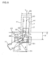
- a rear view camera 2 is mounted to the back of a vehicle 1 as an image capturing means for capturing images of a view behind the vehicle 1.
- a rear bumper 3 of the vehicle 1 comes within a lower end portion of the visual range of the camera 2.
- a monitor 4 constituted of a color-type liquid crystal display is arranged near a driver seat of the vehicle.
- the monitor 4 is normally used as a display device of a navigation system. However, when parking assistance operations according to the present invention are being performed, the monitor 4 displays images taken by the camera 2.
- a shift lever 5 is arranged to one side of the driver seat.
- Front wheels 6, which are wheels that steer the vehicle, are steered by operations with a steering wheel 7.
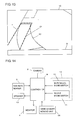
- Fig. 2 shows a structure of a parking assisting device according to Embodiment 1 of the present invention.
- a controller 8 is connected to the camera 2 and the monitor 4.
- Connected to the controller 8 are: a yaw rate sensor 9 for detecting angular speed of the yaw angle direction of the vehicle 1; and a switch module 12 having an in-parallel mode switch 10 for informing the controller 8 that the vehicle 1 performs in-parallel parking and an in-line mode switch 11 for informing the controller 8 that the vehicle 1 performs in-line parking.
- a speaker 13 for providing driving operation information to a driver is connected to the controller 8.
- the controller 8 includes a CPU, a ROM storing control programs, and a RAM used for performing operations.
- the ROM stores a minimum turning radius Rc data used when the steering wheel 7 of the vehicle 1 is turned to its maximum and the vehicle 1 turns, and also stores control programs for performing parking assistance upon in-parallel parking and in-line parking.
- the CPU operates based on the control programs stored in the ROM.
- the controller 8 calculates a yaw angle of the vehicle 1 from an angle speed of the vehicle 1 inputted from the yaw rate sensor 9, and calculates a turning angle of the vehicle 1, and then outputs to a speaker 13 operation methods and operation timing of each step to park the vehicle.
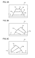
- the controller 8 displays the rear view image captured by the camera 2 on the monitor 4, along with overlapping display of a predicted path 14 for the vehicle 1, shown by the dotted lines in Figs. 3A to 3C.
- Fig. 3A shows the predicted path 14 when the vehicle moves straight backward.
- Fig. 3B shows the predicted path 14 when moving backward with the steering angle at the maximum rightward.
- Fig. 3C shows the predicted path 14 when moving backward with the steering angle at the maximum leftward.
- the predicted paths 14 have a sideline 17a and a sideline 17b on a screen 15 of the monitor 4.
- the sidelines 17a and 17b connect line segments 18, 19, and 16, which are equivalent to a width of 1.8 m created by connecting both ends of the rear bumper 3, advancing from the rear bumper 3 of the vehicle 1 by 0.5 m, 1.5 m and 3 m from the current position of the rear axle center.
- the sidelines 17a and 17b connect both ends of the line segments, and extend as straight lines toward the rear bumper 3, or as smoothly curved lines.
- the predicted path 14 displayed on the monitor 4 becomes the shape extending straight behind the rear bumper 3 as shown in Fig. 3A when moving backward with the steering wheel 7 in the straight state.
- the predicted path 14 becomes the shape curved to the rightward direction or to the leftward direction as shown in Fig. 3B and Fig. 3C, respectively.
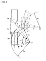
- a rear axle center MO of the vehicle 1 in a vehicle position M1 in this state is assumed to be an origin, and a Y axis is taken in a direction parallel with a road, which is the backward direction of the vehicle 1, and an X axis is taken to be perpendicular to the Y axis.
- coordinates at the corner in the back of the parking space T are assumed to be S2 (W2/2, a).
- "a" and "W2" denote a rear overhang and a vehicle width of the vehicle 1, respectively.
- the vehicle 1 in a vehicle position J1 advances while turning at the minimum turning radius Rc with the steering angle of the steering wheel 7 at the maximum rightward.
- the vehicle 1 stops when it reaches a vehicle position K1, and moves backward while turning at the minimum turning radius Rc with the steering angle at the maximum leftward.
- the vehicle stops and moves backward while turning at the minimum turning radius Rc with the steering angle at the maximum rightward, until it is appropriately parked in the vehicle position M1 within the parking space T.
- in-line parking is started with a vehicle 20 parked in a predetermined position in front of the parking space T as a mark and a state in which the vehicle 1 is parked in the vehicle position J1 as an initial stop position.
- the vehicle position J1 is assumed to be a position where a Y coordinate of a position DR of a driver of the vehicle 1 coincides with the Y coordinate of a rear end 20a of the parked vehicle 20, which is a position in parallel with the parking space T, and a position where the vehicle 1 and the vehicle 20 are shifted from each other by a predetermined distance d. Therefore, coordinates (JOx, JOy) of a rear axle center JO of the vehicle position J1 are unambiguously defined from the relation between the coordinates of the rear end 20a of the vehicle 20, the position DR of the driver, and the rear axle center JO, and from the vehicle distance d.
- the vehicle 1 in the vehicle position J1 advances to the vehicle position K1 while turning at the minimum turning radius Rc with the steering angle of the steering wheel 7 at the maximum rightward.
- a turning center is assumed to be C3 and a turning angle is assumed to be .
- the vehicle 1 in the vehicle position K1 moves backward to the vehicle position L1 while turning at the minimum turning radius Rc with the steering angle at the maximum leftward.
- a turning center is assumed to be C4 and a turning angle is assumed to be ⁇ .
- the steering wheel 7 is turned in the opposite direction in the vehicle position L1 and the vehicle 1 moves backward to the vehicle position M1 while turning at the minimum turning radius Rc with the steering angle at the maximum rightward.
- a turning center is assumed to be C5 and a turning angle is assumed to be ⁇ .
- rear axle centers in the vehicle positions K1 and L1 are assumed to be KO and LO, respectively.
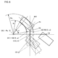
- the rear axle center position is set as a point of origin 0, and a Y-axis is taken along the length direction of the vehicle 1 at the vehicle position L1, and an X-axis is taken perpendicular to the Y-axis.
- coordinates of a rear-right end Q1 are (-W2/2, a)
- coordinates of a rear-left end Q2 are (W2 /2, a)
- coordinates of the turning center C5 are (-Rc, 0).
- Ro ⁇ (Rc+W2/2) 2 +a 2 ⁇ 1/2
- the path of the rear-right end Q1 of the vehicle 1 is defined as P1
- the path of the rear-left end Q2 is defined as P2.
- the path P1 is plotted as an arc having a turning angle . and a radius of Ri from the point Q1 (-W2/2, a), with the turning center C5 (-Rc, 0) as its center.
- the path P2 is plotted as an arc having a turning angle . and a radius of Ro from the point Q2 (W2/2, a), with the turning center C5 (-Rc, 0) as its center.
- the path P1 corresponds to the sideline 17b of the predicted path 14 shown in Fig. 3B
- the path P2 corresponds to the sideline 17a.
- the driver stops the vehicle 1 in the vehicle position J1 so that a Y coordinate of the position DR of the driver coincides with a Y coordinate of the rear end 20a of the parked vehicle 20 and the vehicle 1 is shifted from the vehicle 20 by the vehicle distance d, for example, 50 cm.
- the controller 8 sets the vehicle position J1 as a position where a yaw angle of the vehicle is zero degree and simultaneously activates a program for in-line parking.
- the driver steers the steering wheel 7 of the vehicle 1 to the maximum rightward to bring it to a fully turned state and advances the vehicle 1 in that state.
- the controller 8 calculates a yaw angle of the vehicle from an angular speed of the vehicle 1 inputted from the yaw rate sensor 9 and compares the yaw angle with the value of the turning angle ⁇ (the pre-set prescribed yaw angle). As the vehicle 1 approaches the vehicle position K1 from the vehicle position J1, the controller 8 provides to the driver an approach information to notify that the vehicle has approached the vehicle position K1 and an arrival information to notify that the vehicle has reached the vehicle position K1, based on the difference between the yaw angle and the turning angle ⁇ via the speaker 13.
- an intermittent sound such as "blip, blip” is emitted from the speaker 13 as the approach information, and the cycle of this intermittent sound and blinking becomes shorter as the difference between the yaw angle and the turning angle ⁇ decreases.
- a continuous sound such as "bleep” is emitted from the speaker 13 as the arrival information.
- the driver stops the vehicle 1 in the vehicle position K1 in accordance with the arrival information. Next, the driver steers the steering wheel 7 to the maximum leftward and moves the vehicle 1 backward. At this time, the screen 15 of the monitor 4 switches to show the picture shot by camera 2 from the back of vehicle 1.
- the controller 8 provides to the driver an approach information to notify that the vehicle has approached the vehicle position L1 and an arrival information to notify that the vehicle has reached the vehicle position L1 based on the difference between the yaw angle and the turning angle ⁇ via the speaker 13.
- the driver stops the vehicle 1 at the vehicle position L1 according to the arrival information.
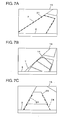
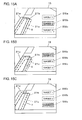
- the controller 8 calculates a predicted parking position, where the vehicle is predicted to stop if the driver continues to perform the driving operations in accordance with the guidance information.
- the controller 8 overlaps a display of a vehicle mark 21 showing an outline image of the vehicle 1 at the predicted parking position.
- the driver confirms whether or not the vehicle mark 21 showing the predicted parking position is accurately aligned inside the target parking space T on the monitor 4, indicated by the solid lines in Fig. 7A.
- the vehicle mark 21 may also be displayed immediately before the vehicle 1 stops on the vehicle position L1.
- the controller 8 calculates the predicted path 14 of the vehicle 1 based on the paths P1 and P2 shown in Fig. 6, and the controller 8 displays the predicted path 14 with lines such as the dotted lines in Fig. 7B so as to overlap with the image behind the vehicle 1 shown on the monitor 4.
- This predicted path 14 enables the driver to confirm whether or not the vehicle 1 can be parked in the target parking space T with the backward operations being performed, and also to confirm whether or not obstructions are present in the backward path of the vehicle.
- the backward movement of the vehicle 1 is started, and when the yaw angle of the vehicle 1 approaches 0°, the controller 8 provides the approach information to notify that the vehicle 1 approached the vehicle position M1 inside the target parking space T and the arrival information to notify that the vehicle arrived at the vehicle position M1 to the driver via the speaker 13. Further, as shown in Fig. 7C, before the vehicle 1 arrives at the vehicle position M1, the controller 8 displays a pair of left/right guide lines 24, so that the driver can confirm whether or not the vehicle 1 is parked in parallel with respect to a neighboring parking space 23 formed behind the target parking space T, or the shoulder of the road. These guide lines 24 correspond to the pair of sidelines 17a and 17b of the predicted path 14 when moving straight backward, which is shown in Fig. 3A. The driver hears the arrival information from the speaker 13 and sees the guidelines 24 on the monitor 4, whereby the driver can stop the vehicle 1 at the vehicle position M1 to complete the parking.
- the driver can return from the vehicle position L1 to the initial stop position J1, and then perform the parking operations again from a position slightly shifted from the initial stop position J1.
- the driver can confirm the alignment of the predicted path 14, the vehicle mark 21, and the target parking space T which are displayed in an overlapping manner on the monitor 4, to thereby judge in advance whether or not the vehicle 1 can be parked in-line into the target parking space T by continuing to perform the driving operations in accordance with the guidance information from the speaker 13.
- the driver can confirm in advance whether or not obstructions are present in the predicted backward path if the driver continues to perform the driving operations in accordance with the guidance information from the speaker 13.
- the driver can visually confirm whether or not the vehicle 1 has reached the position where the steering wheel 7 should be turned to the opposite direction with reference to the alignment of the vehicle mark 21 and the parking space T in the image.
- Fig. 8 is used to explain in-parallel parking.
- a point of origin O is set to the center of the entrance into the parking space T where the vehicle 1 will be parked.
- a Y-axis is established at a perpendicular angle to the road, extending in the rearward direction from the vehicle 1 in the parking space T.
- An X-axis is established as extending parallel to the road, i.e., perpendicular to the Y-axis.
- the width of the parking space T is defined as W1.
- the parking assisting device assists the driver so that the vehicle 1 is appropriately parked with the rear axle center HO at the center of the width direction of the parking space T, and the vehicle 1 is in the vehicle position H1 parallel with the length direction of the parking space T.
- the vehicle 1 is stopped at the initial stop position, which is at a vehicle position E1.
- the vehicle position E1 is perpendicular to the parking space T, with the rear axle center EO of the vehicle 1 being at a distance D from the entrance of the parking space T, and the driver's position DR of the vehicle 1 is aligned with a side portion T1 of the parking space T.
- the steering wheel 7 is turned to the maximum leftward steering angle and the vehicle 1 which is located at the vehicle position E1 turns on the radius Rc, as it advances to the turn angle .
- the steering wheel 7 is turned to the maximum rightward steering angle and the vehicle 1 turns on the turning radius Rc, as it retreats by the turning angle .
- the steering wheel 7 is returned to the straight position, and the vehicle backs up further to park appropriately in the vehicle position H1 inside the parking space T.
- the rear axle center is positioned at E0, F0, and G0, respectively.
- the value of . can be calculated using Rc, L, and W1.
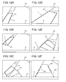
- the plotting of the predicted path is explained in a case where, as shown in Fig. 9, when the vehicle 1 is positioned at the vehicle position F1, the steering wheel 7 is turned to the maximum leftward and the vehicle turns and retreats from the vehicle position F1 to reach the vehicle position G1.
- the vehicle 1 at the vehicle position E1 turns around the turning center C1 on the turning radius Rc at the steering angle of the steering wheel 7 turned to the maximum rightward, as the vehicle 1 advances to the turning angle .
- the vehicle 1 stops and the turning angle of the steering wheel 7 is turned to the maximum leftward, and the vehicle turns around the turning center C2 on the turning radius Rc, as it retreats to the turning angle ..
- the steering wheel 7 When the vehicle 1 stops at the vehicle position G1 parallel with the parking space T, the steering wheel 7 is returned to the straight position, and the vehicle backs up further to park appropriately inside the parking space T.
- the radii from the turning center C2 to the rear-right end and the rear-left end of the vehicle 1 are Ro and Ri, respectively.
- the rear axle center position serves as a point of origin 0, and a Y-axis is taken along the length direction of the vehicle 1 at the vehicle position F1, and an X-axis is taken perpendicular to the Y-axis.
- the coordinates of the rear-right end Q1 are (-W2/2, a)
- the coordinates of the rear-left end Q2 are (W2/2, a)
- the coordinates of the turning center C2 are (Rc, 0).
- Ro ⁇ (Rc+W2/2) 2 +a 2 ⁇ 1/2
- the path of the rear-right end Q1 of the vehicle 1 is defined as P1
- the path of the rear-left end Q2 is defined as P2.
- the path P1 is plotted as an arc having a turning angle . and a radius of Ro from the point Q1 (-W2/2, a), with the turning center C2 (Rc, 0) as its center.
- the path P2 is plotted as an arc having a turning angle . and a radius of Ri from the point Q2 (W2/2, a), with the turning center C2 (Rc, 0) as its center.
- the path P1 corresponds to the sideline 17b of the predicted path 14 shown in Fig. 3C
- the path P2 corresponds to the sideline 17a.
- the straight path Pb of the vehicle 1 can be plotted by tangent lines extending out from the arcs at the end points of the paths P1 and P2.
- the vehicle 1 is stopped at the vehicle position E1, which is the position where the X coordinate of the driver's position DR is aligned with the side portion T1 of the parking space T, and the vehicle 1 is at a distance of, for example, 50 cm from the entrance to the target parking space T.
- the controller 8 when the in-parallel mode switch 10 is turned on, this triggers the controller 8 to set the initial stop position to a position where the yaw angle of the vehicle 1 is 0°, and also load the program for in-parallel parking.
- the driver steers the steering wheel 7 to the maximum leftward, and has the vehicle 1 advance forward in this state.
- the controller 8 calculates the yaw angle of the vehicle 1 based on the angular speed of the vehicle 1, which is inputted form the yaw rate sensor 9, and then compares this yaw rate with the turning angle ., which corresponds to a prescribed yaw rate having been set in advance.
- the controller 8 provides the approach information to notify that the vehicle 1 approached the vehicle position F1 and the arrival information to notify that the vehicle 1 arrived at the vehicle position F1 to the driver via the speaker 13, based on the difference between the yaw angle and the turning angle .
- the driver stops the vehicle 1 at the vehicle position F1 as following the arrival information.
- the screen 15 of the monitor 4 switches to the image behind the vehicle 1 captured by the camera 2.
- the controller 8 begins the same operations as those when performing in-line parking, shown in Figs. 7A to 7C. Namely, the controller 8 calculates the predicted parking position where the vehicle 1 to be parked if the driver continues to perform the parking operations in accordance with the guidance information. Then, on the screen of the monitor 4, the controller 8 performs the overlapping display of the vehicle mark showing the outline image of the vehicle 1 in the predicted parking position. The driver confirms whether or not the vehicle mark, which indicates the predicted parking position, is positioned in the center of the width direction of the target parking space T on the monitor 4.
- the controller 8 calculates the predicted path of the vehicle 1 based on the above-mentioned paths P1 and P2, and the controller 8 displays the predicted path 14 shown such as the dotted lines in Fig. 3B so as to overlap with the image behind the vehicle 1 shown on the monitor 4.
- This predicted path 14 enables the driver to confirm whether or not the vehicle 1 can be parked in the target parking space T with the backward operations, and also to confirm whether or not obstructions are present in the backward path of the vehicle.
- the controller 8 When the vehicle 1 starts to back up, as the yaw angle of the vehicle 1 approaches 90°, the controller 8 provides the approach information to notify that the vehicle 1 approached the vehicle position G1 inside the target parking space T and the arrival information to notify that the vehicle 1 arrived at the vehicle position G1 to the driver via the speaker 13. Further, immediately before the vehicle 1 arrives at the vehicle position G1, the controller 8 calculates and displays a predicted straight path, based on the above-mentioned path Pb, so that the driver can confirm whether or not the vehicle 1 is parallel to the side portion of the target parking space T. Accordingly, the driver stops the vehicle 1 at the vehicle position G1, and then returns the steering wheel 7 to the straight position and moves the vehicle backwards. When the vehicle 1 enters the target parking space T, parking is complete.
- the driver can retry the parking operations from a position slightly shifted from the initial stop position E1.
- the driver can confirm the alignment of the predicted path 14, the vehicle mark, and the target parking space T which are displayed in an overlapping manner on the monitor 4, to thereby judge in advance whether or not the vehicle 1 can be parked in parallel into the target parking space by continuing the driving operations in accordance with the guidance information from the speaker 13.
- the driver can confirm in advance whether or not obstructions are present in the predicted backward path if the driver continues to perform the driving operations in accordance with the guidance information from the speaker 13.
- the predicted path from the vehicle position L1 to the vehicle position M1 was displayed after the vehicle 1 reaches the vehicle position L1 which is the ultimate position where the steering wheel is turned in the opposite direction.
- the ultimate turning path from the vehicle position L1 to the vehicle position M1 can also be displayed as the predicted path.
- the shift lever 5 is put into the reverse position.
- the rear view image captured by the camera 2 is displayed on the monitor 4, and the predicted path from the vehicle position L1 to the vehicle position M1 is also displayed on the monitor 4 in an overlapping manner, to facilitate the subsequent operations for backing up the vehicle.
- the turning center C5 of the ultimate turning paths P1 and P2 from the vehicle position L1 to M1 and the points Q1 and Q2 which are the start points of the paths P1 and P2 are rotated from the turning center C3 and the points Q01 and Q02, respectively, by an angle of -. around the turning center C4.
- the path of the rear-right end P1 of the vehicle 1 is plotted as an arc having a turning angle . and a radius of Ri from the point Q1 (Q1x, Q1y), with the turning center C5 (C5x, C5y) as its center.
- the path of the rear-left end P2 is plotted as an arc having a turning angle . and a radius of Ro from the point Q2 (Q1x, Q1y), with the turning center C5 (C5x, C5y) as its center.
- the controller 8 calculates the predicted path from the vehicle position L1 to M1 based on the paths P1 and P2, and displays the predicted path in the monitor 4 so as to overlap the image behind the vehicle 1 captured by the camera 2.
- the predicted path enables the driver to confirm in advance whether or not the vehicle 1 can be parked into the target parking space T by continuing the operation of backing up, and to confirm whether or not obstructions are present in the backward path.
- the driver can confirm the possibility of parking in the target parking space T and the presence/absence of obstructions. Therefore, he/she can make a quicker judgment regarding returning and trying again from the initial stop position J1, etc.
- the predicted path or the vehicle mark can be displayed once the vehicle 1 reaches the vehicle position J1, which is the initial stop position.
- the controller 8 calculates the predicted parking position that is predicted at this position J1, and displays the vehicle mark 21 at the predicted parking position on the screen 15 of the monitor 4.
- Fig. 12B the vehicle 1 moves forward, and immediately before the vehicle 1 arrives at the vehicle position K1, the vehicle mark 21 is displayed at the predicted parking position that is predicted at this position K1.
- Fig. 12C when the vehicle 1 starts to turn backwards from the vehicle position K1 to the vehicle position L1, the predicted path 14 from the vehicle position K1 to the vehicle position L1 is displayed. Further, as shown in Figs. 12D to 12F, immediately before the vehicle 1 reaches the vehicle position L1, operations similar to those of Embodiment 1 shown in Figs. 7A to 7C are performed.
- the driver may return from the vehicle position K1 or L1 to the initial stop position at vehicle position J1, and may retry the driving operations to park the vehicle from a position slightly shifted from the initial stop position J1. Further, in a case where the vehicle mark 21 displayed at the vehicle position J1 is not aligned with the target parking space T, the driver can move the vehicle 1 slightly before starting the parking operations again.
- the predicted path and the predicted parking position described above enable the driver to confirm in advance whether or not the vehicle 1 can be parked into the target parking space T by continuing to move the vehicle 1 backward, and can confirm whether or not obstructions are present in the backward path.
- Embodiment 3 at the initial stop position at vehicle position J1, the driver can confirm the possibility of parking in the target parking space T and the presence/absence of obstructions. Therefore, he/she can make an even quicker judgment regarding whether to return to the initial stop position and retry the operations, etc.
- a predicted path 25 which incorporates all the predicted paths from each of the vehicle positions J1, K1, and L1 along with the vehicle mark 21 displayed at the position J1.
- the display may alternate between the vehicle mark 21 and the predicted path 25, displaying each for given durations of time.
- the vehicle 1 is also provided with a side monitoring camera on a lateral side of the vehicle 1 to serve as side monitoring means, then, when performing in-parallel parking, the predicted path and the vehicle mark can be displayed from the initial stop position at the vehicle position E1, similarly to the case of performing in-line parking as described above.
- Fig. 14 shows a configuration of a parking assisting device according to Embodiment 4.
- This parking assisting device includes the device of Embodiment 1 shown in Fig. 2, and at the driver seat of the vehicle 1, there is arranged a vehicle mark moving unit 26 for moving the vehicle mark 21 on the screen of the monitor 4. Then, the vehicle mark moving unit 26 is connected to the controller 8. Note that the vehicle mark moving unit 26 constitutes predicted parking position display moving means of the present invention.
- the controller 8 calculates the predicted parking position, and as shown in Fig. 12A, performs the overlapped display of the vehicle mark 21 at the predicted parking position on the screen 15 of the monitor 4. At this time, if there is any misalignment between the initial stop position where the vehicle 1 actually stopped and the vehicle position J1, the vehicle mark 21 does not align with the target parking space T on the monitor 4 and is deviated from the parking space T.
- Embodiment 4 is configured such that the vehicle mark 21 on the monitor 4 can be moved by the vehicle mark moving unit 26 arranged on the driver seat, and when the vehicle mark 21 displayed at the initial stop position is deviated from the parking space T, the driver uses the vehicle mark moving unit 26 to move the vehicle mark 21 to align it with the parking space T.
- the movement by the vehicle mark moving unit 26 includes vertical movement, horizontal movement, and rotation on the monitor 4.
- the controller 8 calculates a gap between the initial stop position where the vehicle actually stopped and the vehicle position J1.
- the controller 8 Based on the calculated gap and the standard coordinates J0x, J0y of the rear axle center J0, the controller 8 obtains the coordinates (J0x + dx, J0y + dy) of the rear axle center J0' at the actual initial stop position, and adjusts the above-mentioned turning angles ., . and . so that the vehicle 1 can be appropriately and parked in-line into the parking space T.
- the adjusted turning angles ., . and . are used as prescribed yaw angles to create the guidance information, which is sent to the driver. Accordingly, the vehicle 1 can be appropriately parked into the parking space T.
- the controller can be given a function to generate the guidance information based on the angle .
- the vehicle 1 can be appropriately parked into the parking space T even in a case where the initial stop position is slanted with respect to the target parking space.
- a movement amount storing unit for storing the movement amount of the vehicle mark 21 moved by the vehicle mark moving unit 26.
- the predicted path 14 and the vehicle mark 21 may be displayed and the guidance information may be generated based on the stored movement amount.
- the movement amount storing unit can be formed by the controller 8.
- the vehicle 1 can be appropriately parked into the parking space T without moving the vehicle 1 to the initial stop position again even if the initial stop position where the vehicle 1 actually stopped is slightly deviated.
- the predicted paths 14 and 25 and the predicted parking position vehicle mark 21 which are displayed on the monitor 4 when performing the parking assistance of Embodiments 1 to 4 move together with the image from the camera 2, as the vehicle 1 moves.
- the relative position of the vehicle 1 to the predicted path and predicted parking position, which are calculated for each vehicle position change as the vehicle 1 moves.
- the parking assistance is performed on the assumption that a turning radius is the minimum turning radius to be Rc, which is achieved by turning the steering wheel 7 to the maximum left or right. Therefore, the amount of change in the relative position of the predicted path and the predicted parking position to the vehicle 1 can be calculated by using the yaw rate sensor 9, etc.
- the change amount is taken into consideration to update the predicted path and the predicted parking position continuously. Accordingly, the predicted path and the vehicle mark which are displayed in an overlapping manner on the monitor 4 can be gradually moved on the monitor 4 as the vehicle 1 moves, so as to always display the same position relative to the image such as road surface captured by the camera 2.
- the driver can confirm at any time whether or not the vehicle 1 can be parked into the parking space T by continuing the driving operations just like that in accordance with the guidance information.
- a parking assisting device when performing in-line parking, before arriving at the initial stop position at the vehicle position J1, the in-line mode switch 11 is turned on and the vehicle mark 21 displaying the predicted parking position is displayed as the vehicle 1 moves forward, and vehicle 1 stops when the vehicle mark 21 approaches most the parking space T in the image.
- the in-line mode switch 11 is turned on once again to thereby output guidance information such as shown in Embodiments 1 to 5 so as to guide the driver through the subsequent driving operations. Those operations enable the vehicle 1 to accurately stop at the initial stop position at the vehicle position J1, thus enabling more precise parking assistance.
- the driver when performing in-parallel parking, in the case where the side monitoring camera is provided, if the driver performs the same operations as in the case of performing in-line parking described above, the driver can confirm the vehicle mark 21 and the parking space T on the monitor 4 as he/she stops the vehicle 1 at the vehicle position E1 that is the initial stop position, thus obtaining the same effect.
- a plurality of predicted parking position are displayed on the screen 15 of the monitor 4, and the driver can select one from those, whereby the subsequent parking guidance can be performed.
- Fig. 15A if the driver stops the vehicle 1 at the initial stop position and operates the in-line mode switch 11, then the three vehicle marks 21a to 21c are displayed in an overlapping manner on the screen 15 of the monitor 4, each at slightly deviated sideways positions. Those vehicle marks 21a to 21c are displayed at predicted parking positions set in advance in the controller 8. Further, as predicted parking position selection means, touch switches SWa to SWc marked as "Target 1" to "Target 3" corresponding to the vehicle marks 21a to 21c, respectively, are displayed on the screen 15.
- the driver selects the vehicle mark closest to the target parking space T from the vehicle marks 21a to 21c on the screen 15, and operates the touch switch corresponding to that vehicle mark.
- the touch switch SWb (“Target 2") is operated to select the vehicle mark 21b.
- the vehicle mark 21a is selected by operating the touch switch SWa ("Target 1")
- the vehicle mark 21c is selected by operating the touch switch SWc ("Target 3"), respectively.
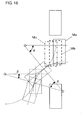
- a corresponding horizontal movement distance DX and vertical movement distance DY are determined. Therefore, as shown in Fig. 16, the target turning angles ., ., and . which correspond to the predicted parking positions Ma, Mb, and Mc displayed at the vehicle marks 21a, 21b, and 21c, respectively can be calculated.
- the driver can perform forward/backward adjustment of the initial stop position by looking at the alignment of the vehicle marks 21a to 21c with the target parking space T on the screen 15, as the driver moves the vehicle 1 forward or backward.
- the vehicle marks 21a to 21c are displayed at positions that are slightly shifted from each other in the forward/backward direction.
- restriction is not made to this configuration.
- the vehicle marks 21a to 21c can be displayed all at the same position with respect to the forward/backward direction, while being shifted in the sideways direction only. However, it is easier for the driver to view and select the vehicle marks 21a to 21c if the marks are displayed at positions shifted in the forward/backward direction.
- the vehicle marks 21a to 21c are shifted in the sideways direction, it is desirable that the marks are shifted by, for example about 20 cm from each other on the actual road surface.
- a dedicated selection switch serving as the predicted parking position selection means can be placed around the edge of the monitor 4 or the like. This selection switch can be used to select the vehicle marks 21a to 21c.
- the number of vehicle marks is not restricted to three.
- two, four, or more vehicle marks can be displayed in an overlapping manner at different positions on the screen 15.
- the plurality of vehicle marks which were slightly shifted from each other in the sideways direction, were used to make adjustments in the sideways direction at the initial stop position.
- a plurality of vehicle marks slightly shifted from each other in the forward/backward direction can be displayed in an overlapping manner on the screen 15 of the monitor 4 so that the driver can use the touch switch or the like corresponding to those vehicle marks to select one of those vehicle marks to make adjustments in the forward/backward direction at the initial stop position.
- Embodiment 6 before arriving at the initial stop position, the vehicle mark was displayed on the image shown on the screen 15, and the vehicle 1 was stopped according to the alignment of the vehicle mark and the target parking space T, whereby the appropriate initial stop position is achieved.
- the vehicle mark is displayed in an overlapping manner in the image on the screen 15, at a position near the reverse movement start position such as the vehicle position K1 in the case of in-line parking as shown in Fig. 4, or the vehicle position F1 in the case of in-parallel parking as shown in Fig. 8, and the vehicle 1 is stopped in accordance with the alignment of the vehicle mark and the target parking space T. Consequently, the appropriate reverse movement start position can be obtained, whereby the vehicle 1 can be led into the target parking space T by performing the subsequent operations as instructed by the guidance information, even in the case where the initial stop position is slightly misaligned.
- the predicted path and the predicted parking position are calculated and displayed as described in Embodiment 2.
- the vehicle position K1 which is the reverse movement start position when performing in-line parking
- the predicted path and the predicted parking position are calculated and displayed as described in Embodiment 2.
- the vehicle mark indicating the predicted parking position will be displayed at the vehicle position M3 which is not aligned with the target parking space T shown in the background.
- this misalignment only occurs in the width direction of the vehicle 1. It is assumed that the parallel relationship with respect to the road, and the setting in the forward/backward direction, are accurate.
- the driver turns on a correction switch (not shown in the figure), making the controller 8 to a correction mode.
- a correction switch (not shown in the figure)
- the vehicle 1 turns and reaches the vehicle position K4.
- the turning angle from the vehicle position J3 is . + ...
- the predicted parking position M3 displayed at the vehicle position K3 is equivalent to the predicted parking position M1 seen from the vehicle position K1, and corresponds to a position obtained by rotating the position M1 seen from the vehicle position J1, i.e. rotating the vehicle position achieved when the rear axle center coordinates are (-J0x, -J0y) and parallel to the vehicle 1 from the position J3 by an amount equivalent to the angle ., around the turning center (-Rc, 0) when moving to the position K1. Therefore, a point of origin is established at the rear axle center when the vehicle 1 is at the vehicle position K3, and a y-axis is taken in the direction rearward therefrom, and an x-axis is taken in a direction perpendicular toward the left.
- this position is set as the rear axle center, and the vehicle mark is displayed on the screen 15 in the monitor 4 at the predicted parking position in such a way that the angle made with the vehicle 1 is . + ...
- This position appears at a position closer to the side of the road than the M3 position plotted when the vehicle 1 was at the vehicle position K3. If the vehicle 1 continues to move forward, the position approaches the side of the road as the vehicle 1 advances. Finally, the vehicle mark is displayed beyond the side of the road.
- the driver makes the vehicle 1 advance or retreat such that the vehicle mark aligns with the target parking space T. In other words, the driver stops the vehicle 1 when appropriately when matching the ...
- the controller 8 calculates the ultimate turning angle .' corresponding to the angle . + ...
- the driver turns the steering angle of the steering wheel 7 in the opposite direction to the maximum leftward and moves the vehicle backward, and then stops the vehicle 1 at a position where the yaw angle of the vehicle 1 becomes .', in accordance with the guidance information from the controller 8. Then, the driver turns the steering angle of the steering wheel 7 in the opposite direction toward the maximum rightward.
- the parking is complete.
- the vehicle mark 1 showing the predicted parking position at an appropriate time after the vehicle 1 starts to advance from the vehicle position J1, e.g., when the actual turning angle of the vehicle 1 exceeds a predetermined value. In such a case, it is not necessary to operate the correction switch (not shown in the diagram).
- the vehicle mark when performing in-parallel parking, the vehicle mark may be displayed in an overlapping manner in the image on the screen 15 near the vehicle position F1 which is the position where the vehicle 1 starts moving in reverse, and the driver can stop the vehicle 1 according to the alignment of the vehicle mark and the target parking space T.
- the initial stop position is slightly misaligned, it is still possible to obtain the reverse start position that is appropriate for guiding the vehicle 1 into the target parking space by continuing to perform the operations thereafter as instructed by the guidance information.
- the vehicle 1 is stopped at the vehicle position E1 which is the initial stop position, and the in-parallel mode switch 10 is turned on to load the parking assistance system.
- the steering angle of the steering wheel 7 is turned to the maximum turn angle and the vehicle moves forward in this state to reach the vehicle position F1 which is the reverse start position
- the vehicle position F1 which is the reverse start position
- the vehicle 1 if the vehicle 1 is stopped at the position F2 that is located in front of the normal calculated stop position F1 and starts to move backward, the vehicle will end up at the vehicle position G2.
- the vehicle 1 goes too far past the normal calculated stop position F1 and stops at the position F3 and starts to move backward, then the vehicle 1 will end up at the vehicle position G3.
- this is based on the assumption that the vehicle 1 is accurately set in a perpendicular relationship to the target parking space T.
- the predicted parking position can be moved along the sideways direction of the target parking space T. Therefore, if the predicted parking positions are displayed by the vehicle marks for each of the reverse start positions, then the driver can adjust the reverse start position such that the vehicle mark is located in the substantial center of the target parking space T, so that as a result of subsequent rearward movement, the vehicle 1 is guided to the center of the target parking space T.
- .1, .2, and .3 are established as the turning angles at each of the vehicle positions F1, F2, and F3 which are the reverse start positions from the vehicle position E1, then, as shown in Fig. 19, the turning angles for moving the vehicle to the vehicle positions G1, G2, and G3 which are the predicted parking positions from the reverse start positions will be ./2-.1, ./2-.2, and ./2-.3, respectively.
- the same method as explained in Embodiment 1 can be used to plot the predicted parking positions and the predicted paths predicted from the initial stop position.
- the vehicle marks showing the predicted parking positions and the predicted paths may be displayed at appropriate timings after the vehicle 1 starts to advance from the vehicle position E1, e.g., when the actual turning angle of the vehicle 1 exceeds a predetermined value.
- Embodiment 8 When performing in-parallel parking in accordance with the above-mentioned Embodiment 8, the guidance began to be provided after stopping at the initial stop position at the angle perpendicular to the target parking space T. However, in Embodiment 9, it is not necessary to stop at the initial stop position. Rather, the vehicle 1 advances to the proximity of the vehicle position F1 which is the reverse start position, and then the rear view image and the predicted path are displayed onto the monitor 4, and in-parallel parking is performed.
- the driver moves the vehicle 1 forward to go past the side of the target parking space T, and then steers the steering wheel 7 in such direction as to move the vehicle away from the target parking space T, and stops the vehicle 1 after advancing to a reverse start position with somewhat angle to the target parking space T.
- the controller 8 calculates the predicted paths P1 and P2 showing both side portions of the vehicle 1 in the case where the steering angle of the steering wheel 7 is the maximum and the vehicle is moved backward, and displays those predicted paths P1 and P2 onto the screen 4 of the monitor 15 together with the image behind the vehicle.
- Those predicted paths P1 and P2 are plotted by, for example, segments at an angle of 60°.
- a "Next Step” switch is operated, and guidance will be given for the driver to turn the steering wheel 7 into the maximum in the opposite direction and back up the vehicle 1.
- the driver turns the steering wheel 7 in the same direction as the steering direction plotted by the predicted paths P1 and P2, in Figs 20B and 20C the steering wheel is turned completely to the left, and the vehicle is slowly reversed, whereby the vehicle 1 can be guided into the target parking space T.
- the turning angle at the final turn for guiding the vehicle 1 into the target parking space T is not determined.
- the controller 8 displays a straight backward path as shown in Fig. 3A.
- the driver puts the steering wheel 7 into the straight-forward position, and views the target parking space T and the straight backward path, which are inside the rear view image on the monitor 4, while moving the vehicle 1 backward, and then stops the vehicle 1 straight inside the target parking space T to complete the in-parallel parking.
- the yaw rate sensor 9 can detect that there is not change in the vehicle 1 angle for a given duration of time, to judge that the driver has stopped the vehicle 1 and is currently steering. Then the controller 8 may begin giving guidance.
- the necessary curve directions of predicted paths P1 and P2 are determined depending on whether the vehicle 1 is turning left or right to perform the in-parallel parking.
- the discrimination between left and right can be performed as follows. Namely, the yaw rate sensor 9 constantly measures the angular speed of the vehicle 1, and for a given duration e.g. several seconds this is held as the vehicle 1 turning angle is updated. Then, the vehicle 1 turning angle (direction) immediately before the in-parallel mode switch 10 is turned on is determined. If the turning direction is to the right side, then the predicted path turning to the left is displayed. If the turning direction is to the left side, then the predicted path turning to the right is displayed.
- the yaw rate sensor 9 detects the turn angle of the vehicle 1, and the approach information and the arrival information were outputted to the driver accordingly.
- the vehicle 1 is moved forward such that the vehicle mark 21 displayed on the screen 15 overlaps with the parking space T in the image, then the vehicle 1 can be parked into the parking space T, even if the yaw rate sensor 9 or other yaw angle detecting means is not provided.
- in-line parking or in-parallel parking was performed either to the left or to the right side.
- present invention can also be applied similarly when parking on the opposite side.
- the display should be made such that an actual vehicle width of 1.8 m is displayed as 2.2 m to provide some leeway, to decrease the danger of interfering with obstructions in the actual operations.
- the predicted paths 14, 25 and the vehicle mark 21 were calculated. However, they may also be set in advance in the controller 8.
- the vehicle mark indicating the predicted parking position, and the predicted path were expressed by line drawings using solid lines and dotted lines.
- the given areas can be filled in or be made partially transparent.
- the predicted path was expressed as the paths traveled by the left and right ends of the rear bumper.
- the invention is not restricted to this configuration. Rather, the predicted path may include the paths of the left and right ends of the front bumper, for example.
- the predicted path is expressed as an area, it is possible to express the outer form of the path traveled by surface of the shape of the vehicle. In such a case, the driver can confirm the presence/absence of not only interference with the back end of the vehicle, but also of interference with all portions.
- a parking assisting device including: an image capturing unit for capturing at least an image behind the vehicle; a monitor arranged near a driver seat of the vehicle for displaying the image obtained by the image capturing unit; a yaw angle detecting unit for detecting a yaw angle of the vehicle; a guiding unit for outputting the guidance information regarding the driving operations to the driver; and a controller for comparing a prescribed yaw angle corresponding to a predetermined vehicle position with the yaw angle of the vehicle detected by the yaw angle detecting unit, to identify a current position of the vehicle, and providing the guidance information via the guiding unit while displaying at least one of a predicted path and a predicted parking position on the monitor so as to overlap with the image obtained by the image capturing unit to enable the driver to confirm whether or not the vehicle can be parked into the target parking space by continuing the driving operations in accordance with the guidance information.
Landscapes
- Engineering & Computer Science (AREA)
- Mechanical Engineering (AREA)
- Chemical & Material Sciences (AREA)
- Combustion & Propulsion (AREA)
- Transportation (AREA)
- Closed-Circuit Television Systems (AREA)
- Traffic Control Systems (AREA)
- Devices For Conveying Motion By Means Of Endless Flexible Members (AREA)
- Non-Portable Lighting Devices Or Systems Thereof (AREA)
- Liquid Crystal (AREA)
Applications Claiming Priority (4)
| Application Number | Priority Date | Filing Date | Title |
|---|---|---|---|
| JP2003019872 | 2003-01-29 | ||
| JP2003019872 | 2003-01-29 | ||
| JP2003032656A JP4427953B2 (ja) | 2003-01-29 | 2003-02-10 | 駐車支援装置 |
| JP2003032656 | 2003-02-10 |
Publications (3)
| Publication Number | Publication Date |
|---|---|
| EP1442962A2 true EP1442962A2 (de) | 2004-08-04 |
| EP1442962A3 EP1442962A3 (de) | 2005-03-23 |
| EP1442962B1 EP1442962B1 (de) | 2007-02-14 |
Family
ID=32658597
Family Applications (1)
| Application Number | Title | Priority Date | Filing Date |
|---|---|---|---|
| EP03027693A Expired - Lifetime EP1442962B1 (de) | 2003-01-29 | 2003-12-03 | Parkhilfe |
Country Status (9)
| Country | Link |
|---|---|
| US (1) | US7257486B2 (de) |
| EP (1) | EP1442962B1 (de) |
| JP (1) | JP4427953B2 (de) |
| KR (1) | KR100576280B1 (de) |
| CN (1) | CN1295112C (de) |
| AT (1) | ATE353806T1 (de) |
| AU (1) | AU2004200151B2 (de) |
| DE (1) | DE60311762T2 (de) |
| TW (1) | TWI229645B (de) |
Cited By (7)
| Publication number | Priority date | Publication date | Assignee | Title |
|---|---|---|---|---|
| WO2007042360A1 (de) * | 2005-10-10 | 2007-04-19 | Robert Bosch Gmbh | Verfahren und system zur unterstützung des fahrers eines kraftfahrzeugs bei der erkennung der umgebung des kraftfahrzeugs |
| WO2009044513A1 (en) * | 2007-10-01 | 2009-04-09 | Nissan Motor Co., Ltd. | Parking assistant and parking assisting method |
| WO2009046888A1 (de) * | 2007-10-02 | 2009-04-16 | Valeo Schalter Und Sensoren Gmbh | Verfahren und anordnung zur steuerung eines parkassistenzsystems für fahrzeuge in begrenzten parkräumen |
| EP1908666A3 (de) * | 2006-10-07 | 2012-04-25 | Hella KGaA Hueck & Co. | Verfahren zur Unterstützung des Fahrers eines Kraftfahrzeuges bei einem Einparkvorgang |
| EP2675683A4 (de) * | 2011-02-16 | 2014-08-13 | Lg Innotek Co Ltd | Kameramodul für ein kraftfahrzeug, ansteuerverfahren dafür und verfahren zur parkanweisung |
| US8988250B2 (en) | 2007-10-01 | 2015-03-24 | Nissan Motor Co., Ltd. | Parking assistant and parking assisting method |
| CN114407005A (zh) * | 2021-12-02 | 2022-04-29 | 国能铁路装备有限责任公司 | 一种机器人及其行走控制方法、装置 |
Families Citing this family (92)
| Publication number | Priority date | Publication date | Assignee | Title |
|---|---|---|---|---|
| DE10331235A1 (de) * | 2003-07-10 | 2005-02-03 | Robert Bosch Gmbh | Fahrhilfsvorrichtung insbesondere zum Einparken eines Fahrzeugs |
| JP3931857B2 (ja) | 2003-07-23 | 2007-06-20 | トヨタ自動車株式会社 | 駐車支援装置及び後退支援装置 |
| JP4438499B2 (ja) * | 2004-04-26 | 2010-03-24 | 株式会社豊田自動織機 | 旋回半径算出方法、該旋回半径算出方法を用いた操舵支援装置及び駐車支援装置、旋回半径算出プログラム及び記録媒体 |
| EP2650346A1 (de) | 2004-04-28 | 2013-10-16 | Headwaters Heavy Oil, LLC | Verfahren zur Schwerölhydrierung in einem Wirbelschichtreaktor |
| US7599771B2 (en) * | 2004-05-06 | 2009-10-06 | Panasonic Corporation | Parking assisting apparatus |
| DE102004047481A1 (de) * | 2004-09-30 | 2006-04-13 | Robert Bosch Gmbh | Verfahren zur Anzeige eines Fahrzeugfahrraums |
| DE102004053158A1 (de) * | 2004-11-03 | 2006-05-04 | Robert Bosch Gmbh | Vorrichtung zur Unterstützung des Einparkvorgangs bei Fahrzeugen |
| JP4604703B2 (ja) * | 2004-12-21 | 2011-01-05 | アイシン精機株式会社 | 駐車補助装置 |
| JP4437071B2 (ja) | 2004-12-24 | 2010-03-24 | パナソニック株式会社 | 運転支援装置 |
| US20060161713A1 (en) * | 2005-01-20 | 2006-07-20 | Belady Christian L | Mounting a computer in a transport vehicle |
| DE102005009703A1 (de) * | 2005-03-03 | 2006-09-14 | Robert Bosch Gmbh | Parkhilfsvorrichtung und Verfahren zur Parkunterstützung |
| JP4543983B2 (ja) | 2005-03-22 | 2010-09-15 | 株式会社豊田自動織機 | 駐車支援装置 |
| DE102005027165B4 (de) * | 2005-06-13 | 2024-01-25 | Robert Bosch Gmbh | Verfahren und Vorrichtung zur Ausgabe von Einparkhinweisen |
| JP4596254B2 (ja) * | 2005-06-13 | 2010-12-08 | アイシン精機株式会社 | 運転支援装置 |
| JP4835109B2 (ja) * | 2005-10-31 | 2011-12-14 | アイシン精機株式会社 | 駐車目標位置設定装置 |
| US8035531B2 (en) | 2005-10-31 | 2011-10-11 | Toyota Jidosha Kabushiki Kaisha | Parking support device |
| JP4414959B2 (ja) * | 2005-11-16 | 2010-02-17 | アイシン精機株式会社 | 駐車支援装置 |
| JP2009525227A (ja) * | 2006-02-03 | 2009-07-09 | サンドール コンコリー | オートバイの制動挙動のリアルタイムデモンストレーション用の視覚情報装置 |
| EP1995557B1 (de) * | 2006-03-14 | 2012-12-26 | Pioneer Corporation | Positionserfassungsvorrichtung, routensuchvorrichtung, positionserfassungsverfahren, positionserfassungsprogramm und aufzeichnungsmedium |
| JP4769625B2 (ja) * | 2006-04-25 | 2011-09-07 | トヨタ自動車株式会社 | 駐車支援装置及び駐車支援方法 |
| US7498954B2 (en) * | 2006-05-31 | 2009-03-03 | International Business Machines Corporation | Cooperative parking |
| JP4904997B2 (ja) * | 2006-08-29 | 2012-03-28 | アイシン・エィ・ダブリュ株式会社 | 駐車支援方法及び駐車支援装置 |
| JP4927514B2 (ja) * | 2006-12-12 | 2012-05-09 | クラリオン株式会社 | 運転支援装置 |
| US20080154464A1 (en) * | 2006-12-26 | 2008-06-26 | Honda Motor Co., Ltd. | Automatic Parking control apparatus for vehicle |
| JP4853712B2 (ja) * | 2006-12-28 | 2012-01-11 | アイシン精機株式会社 | 駐車支援装置 |
| KR100974704B1 (ko) | 2007-04-30 | 2010-08-06 | 현대자동차주식회사 | 자동차의 주차 안내 방법 |
| US8034232B2 (en) | 2007-10-31 | 2011-10-11 | Headwaters Technology Innovation, Llc | Methods for increasing catalyst concentration in heavy oil and/or coal resid hydrocracker |
| TWI315271B (en) | 2007-12-27 | 2009-10-01 | Ind Tech Res Inst | Parking guidance device and method thereof |
| US8142645B2 (en) | 2008-01-03 | 2012-03-27 | Headwaters Technology Innovation, Llc | Process for increasing the mono-aromatic content of polynuclear-aromatic-containing feedstocks |
| JP5636609B2 (ja) | 2008-05-08 | 2014-12-10 | アイシン精機株式会社 | 車両周辺表示装置 |
| JP4623393B2 (ja) * | 2008-05-08 | 2011-02-02 | アイシン精機株式会社 | 車両周辺表示装置 |
| JP5380994B2 (ja) * | 2008-10-10 | 2014-01-08 | 日産自動車株式会社 | 駐車支援装置及び駐車支援方法 |
| JP4702432B2 (ja) * | 2008-10-31 | 2011-06-15 | トヨタ自動車株式会社 | 駐車支援装置 |
| DE102008057670B4 (de) * | 2008-11-17 | 2017-01-26 | Eberhard App | Verfahren zur Unterstützung eines Fahrzeugführers eines Fahrzeuges, insbesondere bei einer Rückwärtsfahrt |
| DE102008044073A1 (de) * | 2008-11-26 | 2010-05-27 | Robert Bosch Gmbh | Steuereinrichtung zur Einparkunterstützung |
| DE102009027820A1 (de) * | 2009-07-20 | 2011-01-27 | Robert Bosch Gmbh | Vorrichtung und Verfahren zum unterstützten Einparken eines Fahrzeugs |
| WO2011014482A1 (en) | 2009-07-27 | 2011-02-03 | Magna Electronics Inc. | Parking assist system |
| KR20120048669A (ko) * | 2009-08-03 | 2012-05-15 | 퀄컴 엠이엠에스 테크놀로지스, 인크. | 도광체 조명용의 미세구조체 |
| WO2011039822A1 (ja) * | 2009-10-02 | 2011-04-07 | 三菱電機株式会社 | 駐車支援装置 |
| US8396653B2 (en) * | 2010-02-12 | 2013-03-12 | Robert Bosch Gmbh | Dynamic range display for automotive rear-view and parking systems |
| DE102010020204A1 (de) * | 2010-05-12 | 2011-11-17 | Volkswagen Ag | Verfahren zum Einparken eines Fahrzeugs sowie entsprechendes Einparkassistenzsystem und Fahrzeug |
| JP5501452B2 (ja) * | 2010-05-19 | 2014-05-21 | 三菱電機株式会社 | 車両後方監視装置 |
| EP2581272B1 (de) * | 2010-06-11 | 2014-10-08 | Nissan Motor Co., Ltd | Parkhilfevorrichtung und -verfahren |
| DE102010034139A1 (de) * | 2010-08-12 | 2012-02-16 | Valeo Schalter Und Sensoren Gmbh | Verfahren zur Unterstützung eines Parkvorgangs eines Kraftfahrzeugs, Fahrerassistenzsystem und Kraftfahrzeug |
| US8773285B2 (en) | 2010-12-28 | 2014-07-08 | Automotive Research & Test Center | Parking pilot method and device |
| KR101803973B1 (ko) | 2011-05-09 | 2017-12-01 | 엘지이노텍 주식회사 | 주차용 카메라 시스템과 그의 구동 방법 |
| CN102795166A (zh) * | 2011-05-25 | 2012-11-28 | 怡利电子工业股份有限公司 | 倒车轨迹导引方法 |
| WO2013024523A1 (ja) * | 2011-08-12 | 2013-02-21 | トヨタ自動車株式会社 | 駐車支援装置 |
| KR101842277B1 (ko) * | 2011-10-06 | 2018-03-26 | 엘지이노텍 주식회사 | 주차지원을 위한 디스플레이 방법 |
| TWI488767B (zh) * | 2012-05-03 | 2015-06-21 | E Lead Electronic Co Ltd | 倒車停車指揮系統的倒車導引方法 |
| KR20140014822A (ko) * | 2012-07-26 | 2014-02-06 | 현대모비스 주식회사 | 차량 주차 보조 방법 및 장치 |
| JP2014043153A (ja) * | 2012-08-27 | 2014-03-13 | E-Lead Electronic Co Ltd | 逆転駐車指揮システムの逆転駐車ガイド方法 |
| CN103625467A (zh) * | 2012-08-28 | 2014-03-12 | 怡利电子工业股份有限公司 | 倒车停车指挥系统的倒车导引方法 |
| CN103786662B (zh) * | 2012-10-31 | 2016-06-15 | 上海博泰悦臻电子设备制造有限公司 | 倒车辅助线的生成方法及装置 |
| JP5915771B2 (ja) * | 2012-11-27 | 2016-05-11 | 日産自動車株式会社 | 車両用加速抑制装置及び車両用加速抑制方法 |
| KR101509880B1 (ko) * | 2013-02-28 | 2015-04-07 | 현대자동차주식회사 | 주차 안내 장치 및 방법 |
| KR101426468B1 (ko) * | 2013-05-07 | 2014-08-05 | 현대모비스 주식회사 | Avm 상에서의 차량의 주차 안내 방법 |
| KR20140147205A (ko) * | 2013-06-18 | 2014-12-30 | 삼성전자주식회사 | 휴대 가능한 의료 진단 장치의 주행 경로 제공 방법 및 장치 |
| US9323993B2 (en) * | 2013-09-05 | 2016-04-26 | Xerox Corporation | On-street parking management methods and systems for identifying a vehicle via a camera and mobile communications devices |
| US10328932B2 (en) | 2014-06-02 | 2019-06-25 | Magna Electronics Inc. | Parking assist system with annotated map generation |
| JP6248836B2 (ja) * | 2014-07-10 | 2017-12-20 | 株式会社デンソー | 運転支援装置 |
| JP6022517B2 (ja) * | 2014-09-12 | 2016-11-09 | アイシン精機株式会社 | 車両の制御装置 |
| US9944407B2 (en) | 2014-09-22 | 2018-04-17 | Gulfstream Aerospace Corporation | Methods and systems for avoiding a collision between an aircraft and an obstacle using a three dimensional visual indication of an aircraft wingtip path |
| US9381859B2 (en) | 2014-10-27 | 2016-07-05 | Toyota Motor Engineering & Manufacturing North America, Inc. | Reverse parking assistance with rear visual indicator |
| JP2015096422A (ja) * | 2015-02-11 | 2015-05-21 | 怡利電子工業股▲ふん▼有限公司 | 逆転駐車指揮システムの逆転駐車ガイド方法 |
| DE102015203619A1 (de) * | 2015-02-28 | 2016-09-01 | Bayerische Motoren Werke Aktiengesellschaft | Parkassistenzsystem mit Erkennung einer Universalparklücke |
| US10214206B2 (en) | 2015-07-13 | 2019-02-26 | Magna Electronics Inc. | Parking assist system for vehicle |
| US10078789B2 (en) | 2015-07-17 | 2018-09-18 | Magna Electronics Inc. | Vehicle parking assist system with vision-based parking space detection |
| KR101806619B1 (ko) * | 2015-09-21 | 2017-12-07 | 현대자동차주식회사 | 차량의 주차 안내 장치 및 방법 |
| US11414607B2 (en) | 2015-09-22 | 2022-08-16 | Hydrocarbon Technology & Innovation, Llc | Upgraded ebullated bed reactor with increased production rate of converted products |
| US11414608B2 (en) | 2015-09-22 | 2022-08-16 | Hydrocarbon Technology & Innovation, Llc | Upgraded ebullated bed reactor used with opportunity feedstocks |
| US10683035B2 (en) | 2015-12-08 | 2020-06-16 | Panasonic Intellectual Property Management Co., Ltd. | Parking assistance device, parking assistance method, and non-transitory computer readable medium |
| JP6602683B2 (ja) * | 2016-02-05 | 2019-11-06 | 株式会社東芝 | 充電装置および位置ずれ検出方法 |
| US10160437B2 (en) | 2016-02-29 | 2018-12-25 | Magna Electronics Inc. | Vehicle control system with reverse assist |
| US20170253237A1 (en) | 2016-03-02 | 2017-09-07 | Magna Electronics Inc. | Vehicle vision system with automatic parking function |
| EP3443429B1 (de) * | 2016-04-12 | 2020-12-02 | Agjunction LLC | Erzeugung eines leitungserfassungspfades mittels krümmungsprofilen |
| US11421164B2 (en) | 2016-06-08 | 2022-08-23 | Hydrocarbon Technology & Innovation, Llc | Dual catalyst system for ebullated bed upgrading to produce improved quality vacuum residue product |
| CN109070879B (zh) * | 2016-08-09 | 2021-05-07 | Jvc 建伍株式会社 | 显示控制装置、显示装置、显示控制方法以及存储介质 |
| CN106601076B (zh) * | 2016-11-11 | 2019-06-18 | 长安大学 | 一种基于捷联惯导和面阵相机的汽车自助训练装置及方法 |
| JP6515912B2 (ja) * | 2016-12-22 | 2019-05-22 | トヨタ自動車株式会社 | 車両運転支援装置 |
| JP6544348B2 (ja) | 2016-12-22 | 2019-07-17 | トヨタ自動車株式会社 | 車両運転支援装置 |
| US10369988B2 (en) * | 2017-01-13 | 2019-08-06 | Ford Global Technologies, Llc | Autonomous parking of vehicles inperpendicular parking spots |
| JP6958117B2 (ja) * | 2017-08-29 | 2021-11-02 | 株式会社アイシン | 駐車支援装置 |
| CN111339620B (zh) * | 2018-11-30 | 2023-09-05 | 深圳市航盛电子股份有限公司 | 一种动态辅助线精度测试方法及系统 |
| JP7319590B2 (ja) * | 2019-10-11 | 2023-08-02 | トヨタ自動車株式会社 | 車両駐車支援装置 |
| CN111746522B (zh) * | 2020-06-29 | 2021-08-27 | 广州橙行智动汽车科技有限公司 | 一种泊车交互方法和装置 |
| CN112208518B (zh) * | 2020-09-28 | 2022-02-01 | 惠州华阳通用电子有限公司 | 一种泊车路径自动规划方法 |
| JP2022154517A (ja) * | 2021-03-30 | 2022-10-13 | パナソニックIpマネジメント株式会社 | 駐車支援装置および駐車支援方法 |
| DE102021203825B4 (de) * | 2021-04-19 | 2022-11-17 | Continental Autonomous Mobility Germany GmbH | Verfahren und System zur Optimierung eines detektierten Parkplatzes |
| DE102021132711A1 (de) * | 2021-12-10 | 2023-06-15 | Valeo Schalter Und Sensoren Gmbh | Verfahren zum betreiben eines fahrzeugs, computerprogramm, steuerungssystem sowie fahrzeug |
| JP7797252B2 (ja) * | 2022-03-09 | 2026-01-13 | 株式会社ジェイテクト | 操舵制御装置 |
| CN115752503B (zh) * | 2023-01-09 | 2023-04-21 | 徐工汉云技术股份有限公司 | 园区导航路径规划方法和装置 |
Citations (1)
| Publication number | Priority date | Publication date | Assignee | Title |
|---|---|---|---|---|
| JP2001322520A (ja) | 1999-09-28 | 2001-11-20 | Toyota Industries Corp | 駐車支援装置 |
Family Cites Families (11)
| Publication number | Priority date | Publication date | Assignee | Title |
|---|---|---|---|---|
| JPH10244891A (ja) * | 1997-03-07 | 1998-09-14 | Nissan Motor Co Ltd | 駐車補助装置 |
| EP1043191B1 (de) * | 1999-03-19 | 2003-07-30 | Yazaki Corporation | Rückblickeinrichtung für ein Fahrzeug |
| US6611744B1 (en) * | 1999-08-12 | 2003-08-26 | Kabushiki Kaisha Toyoda Jidoshokki Seisakusho | Steering assist apparatus for traveling in reverse |
| JP3298851B2 (ja) * | 1999-08-18 | 2002-07-08 | 松下電器産業株式会社 | 多機能車載カメラシステムと多機能車載カメラの画像表示方法 |
| JP3508665B2 (ja) * | 1999-12-24 | 2004-03-22 | 株式会社豊田自動織機 | 操舵支援装置 |
| JP3575365B2 (ja) | 1999-12-28 | 2004-10-13 | 株式会社豊田自動織機 | 縦列駐車時の操舵支援装置 |
| JP3427823B2 (ja) * | 2000-02-29 | 2003-07-22 | 株式会社豊田自動織機 | 縦列駐車時の車両後退支援装置 |
| EP1199225B1 (de) * | 2000-05-12 | 2009-07-15 | Kabushiki Kaisha Toyota Jidoshokki | Hilfe beim rückwärtsfahren einen fahrzeugs |
| JP2003072495A (ja) * | 2001-09-06 | 2003-03-12 | Yazaki Corp | 駐車支援装置および駐車支援方法 |
| JP4108314B2 (ja) * | 2001-10-31 | 2008-06-25 | トヨタ自動車株式会社 | 車両用周辺監視装置 |
| JP4342146B2 (ja) * | 2002-04-08 | 2009-10-14 | アイシン精機株式会社 | 駐車補助装置 |
-
2003
- 2003-02-10 JP JP2003032656A patent/JP4427953B2/ja not_active Expired - Fee Related
- 2003-12-03 EP EP03027693A patent/EP1442962B1/de not_active Expired - Lifetime
- 2003-12-03 DE DE60311762T patent/DE60311762T2/de not_active Expired - Lifetime
- 2003-12-03 AT AT03027693T patent/ATE353806T1/de not_active IP Right Cessation
- 2003-12-10 US US10/733,497 patent/US7257486B2/en not_active Expired - Fee Related
- 2003-12-31 KR KR1020030101264A patent/KR100576280B1/ko not_active Expired - Fee Related
-
2004
- 2004-01-15 AU AU2004200151A patent/AU2004200151B2/en not_active Ceased
- 2004-01-20 TW TW093101451A patent/TWI229645B/zh not_active IP Right Cessation
- 2004-01-29 CN CNB2004100035172A patent/CN1295112C/zh not_active Expired - Fee Related
Patent Citations (1)
| Publication number | Priority date | Publication date | Assignee | Title |
|---|---|---|---|---|
| JP2001322520A (ja) | 1999-09-28 | 2001-11-20 | Toyota Industries Corp | 駐車支援装置 |
Cited By (11)
| Publication number | Priority date | Publication date | Assignee | Title |
|---|---|---|---|---|
| WO2007042360A1 (de) * | 2005-10-10 | 2007-04-19 | Robert Bosch Gmbh | Verfahren und system zur unterstützung des fahrers eines kraftfahrzeugs bei der erkennung der umgebung des kraftfahrzeugs |
| EP1908666A3 (de) * | 2006-10-07 | 2012-04-25 | Hella KGaA Hueck & Co. | Verfahren zur Unterstützung des Fahrers eines Kraftfahrzeuges bei einem Einparkvorgang |
| WO2009044513A1 (en) * | 2007-10-01 | 2009-04-09 | Nissan Motor Co., Ltd. | Parking assistant and parking assisting method |
| EP2298627A1 (de) | 2007-10-01 | 2011-03-23 | Nissan Motor Co., Ltd. | Parkassitent und Parkassistenzverfahren |
| EP2301823A1 (de) | 2007-10-01 | 2011-03-30 | Nissan Motor Co., Ltd. | Parkassistent und Parkassistenzverfahren |
| US8855850B2 (en) | 2007-10-01 | 2014-10-07 | Nissan Motor Co., Ltd. | Parking assistant and parking assisting method |
| US8988250B2 (en) | 2007-10-01 | 2015-03-24 | Nissan Motor Co., Ltd. | Parking assistant and parking assisting method |
| WO2009046888A1 (de) * | 2007-10-02 | 2009-04-16 | Valeo Schalter Und Sensoren Gmbh | Verfahren und anordnung zur steuerung eines parkassistenzsystems für fahrzeuge in begrenzten parkräumen |
| EP2675683A4 (de) * | 2011-02-16 | 2014-08-13 | Lg Innotek Co Ltd | Kameramodul für ein kraftfahrzeug, ansteuerverfahren dafür und verfahren zur parkanweisung |
| US9707890B2 (en) | 2011-02-16 | 2017-07-18 | Lg Innotek Co., Ltd. | Automobile camera module, method of driving the same and method of guiding parking |
| CN114407005A (zh) * | 2021-12-02 | 2022-04-29 | 国能铁路装备有限责任公司 | 一种机器人及其行走控制方法、装置 |
Also Published As
| Publication number | Publication date |
|---|---|
| AU2004200151B2 (en) | 2006-05-18 |
| US7257486B2 (en) | 2007-08-14 |
| KR20040069961A (ko) | 2004-08-06 |
| DE60311762D1 (de) | 2007-03-29 |
| TWI229645B (en) | 2005-03-21 |
| TW200500242A (en) | 2005-01-01 |
| US20040153243A1 (en) | 2004-08-05 |
| AU2004200151A1 (en) | 2004-08-12 |
| CN1522892A (zh) | 2004-08-25 |
| ATE353806T1 (de) | 2007-03-15 |
| EP1442962B1 (de) | 2007-02-14 |
| CN1295112C (zh) | 2007-01-17 |
| JP4427953B2 (ja) | 2010-03-10 |
| KR100576280B1 (ko) | 2006-05-04 |
| JP2004284370A (ja) | 2004-10-14 |
| EP1442962A3 (de) | 2005-03-23 |
| DE60311762T2 (de) | 2007-11-15 |
Similar Documents
| Publication | Publication Date | Title |
|---|---|---|
| EP1442962A2 (de) | Parkhilfe | |
| EP1215089B1 (de) | Einparkhilfe | |
| JP3700614B2 (ja) | 駐車支援装置 | |
| US7755511B2 (en) | Parking assistance apparatus | |
| JP4161573B2 (ja) | 駐車支援装置 | |
| JP4466200B2 (ja) | 駐車支援装置 | |
| JP3183284B2 (ja) | 車両の後退時の操舵支援装置 | |
| KR100543642B1 (ko) | 차량용 주차 어시스턴스 장치 및 방법, 그 장치를 포함하는 자동차 | |
| EP1950097B1 (de) | Parkhilfevorrichtung | |
| US6940423B2 (en) | Device for monitoring area around vehicle | |
| US6704653B2 (en) | Vehicle backing support apparatus | |
| JP4094325B2 (ja) | 駐車運転支援装置 | |
| GB2398049A (en) | Vehicle steering aid system | |
| JP5446139B2 (ja) | 駐車支援装置及び駐車支援方法 | |
| JP3664108B2 (ja) | 駐車支援装置 | |
| JP2001158313A (ja) | 車両の後退時の操舵支援装置及び縦列駐車方法 | |
| JP3436237B2 (ja) | 駐車支援装置 | |
| JP3632627B2 (ja) | 駐車支援装置 | |
| JP3630115B2 (ja) | 駐車支援装置 | |
| JP3632631B2 (ja) | 駐車支援装置 | |
| JP3546863B2 (ja) | 駐車支援装置 | |
| JP4491671B2 (ja) | 駐車支援装置 | |
| JP3632629B2 (ja) | 駐車支援装置 |
Legal Events
| Date | Code | Title | Description |
|---|---|---|---|
| PUAI | Public reference made under article 153(3) epc to a published international application that has entered the european phase |
Free format text: ORIGINAL CODE: 0009012 |
|
| AK | Designated contracting states |
Kind code of ref document: A2 Designated state(s): AT BE BG CH CY CZ DE DK EE ES FI FR GB GR HU IE IT LI LU MC NL PT RO SE SI SK TR |
|
| AX | Request for extension of the european patent |
Extension state: AL LT LV |
|
| PUAL | Search report despatched |
Free format text: ORIGINAL CODE: 0009013 |
|
| AK | Designated contracting states |
Kind code of ref document: A3 Designated state(s): AT BE BG CH CY CZ DE DK EE ES FI FR GB GR HU IE IT LI LU MC NL PT RO SE SI SK TR |
|
| AX | Request for extension of the european patent |
Extension state: AL LT LV |
|
| 17P | Request for examination filed |
Effective date: 20050720 |
|
| AKX | Designation fees paid |
Designated state(s): AT BE BG CH CY CZ DE DK EE ES FI FR GB GR HU IE IT LI LU MC NL PT RO SE SI SK TR |
|
| AXX | Extension fees paid |
Extension state: LV Payment date: 20031203 Extension state: LT Payment date: 20031203 Extension state: AL Payment date: 20031203 |
|
| GRAP | Despatch of communication of intention to grant a patent |
Free format text: ORIGINAL CODE: EPIDOSNIGR1 |
|
| GRAS | Grant fee paid |
Free format text: ORIGINAL CODE: EPIDOSNIGR3 |
|
| GRAA | (expected) grant |
Free format text: ORIGINAL CODE: 0009210 |
|
| AK | Designated contracting states |
Kind code of ref document: B1 Designated state(s): AT BE BG CH CY CZ DE DK EE ES FI FR GB GR HU IE IT LI LU MC NL PT RO SE SI SK TR |
|
| AX | Request for extension of the european patent |
Extension state: AL LT LV |
|
| PG25 | Lapsed in a contracting state [announced via postgrant information from national office to epo] |
Ref country code: BE Free format text: LAPSE BECAUSE OF FAILURE TO SUBMIT A TRANSLATION OF THE DESCRIPTION OR TO PAY THE FEE WITHIN THE PRESCRIBED TIME-LIMIT Effective date: 20070214 Ref country code: SI Free format text: LAPSE BECAUSE OF FAILURE TO SUBMIT A TRANSLATION OF THE DESCRIPTION OR TO PAY THE FEE WITHIN THE PRESCRIBED TIME-LIMIT Effective date: 20070214 Ref country code: LI Free format text: LAPSE BECAUSE OF FAILURE TO SUBMIT A TRANSLATION OF THE DESCRIPTION OR TO PAY THE FEE WITHIN THE PRESCRIBED TIME-LIMIT Effective date: 20070214 Ref country code: AT Free format text: LAPSE BECAUSE OF FAILURE TO SUBMIT A TRANSLATION OF THE DESCRIPTION OR TO PAY THE FEE WITHIN THE PRESCRIBED TIME-LIMIT Effective date: 20070214 Ref country code: DK Free format text: LAPSE BECAUSE OF FAILURE TO SUBMIT A TRANSLATION OF THE DESCRIPTION OR TO PAY THE FEE WITHIN THE PRESCRIBED TIME-LIMIT Effective date: 20070214 Ref country code: FI Free format text: LAPSE BECAUSE OF FAILURE TO SUBMIT A TRANSLATION OF THE DESCRIPTION OR TO PAY THE FEE WITHIN THE PRESCRIBED TIME-LIMIT Effective date: 20070214 Ref country code: CH Free format text: LAPSE BECAUSE OF FAILURE TO SUBMIT A TRANSLATION OF THE DESCRIPTION OR TO PAY THE FEE WITHIN THE PRESCRIBED TIME-LIMIT Effective date: 20070214 Ref country code: NL Free format text: LAPSE BECAUSE OF FAILURE TO SUBMIT A TRANSLATION OF THE DESCRIPTION OR TO PAY THE FEE WITHIN THE PRESCRIBED TIME-LIMIT Effective date: 20070214 |
|
| REG | Reference to a national code |
Ref country code: GB Ref legal event code: FG4D |
|
| REG | Reference to a national code |
Ref country code: CH Ref legal event code: EP |
|
| REF | Corresponds to: |
Ref document number: 60311762 Country of ref document: DE Date of ref document: 20070329 Kind code of ref document: P |
|
| REG | Reference to a national code |
Ref country code: IE Ref legal event code: FG4D |
|
| PG25 | Lapsed in a contracting state [announced via postgrant information from national office to epo] |
Ref country code: SE Free format text: LAPSE BECAUSE OF FAILURE TO SUBMIT A TRANSLATION OF THE DESCRIPTION OR TO PAY THE FEE WITHIN THE PRESCRIBED TIME-LIMIT Effective date: 20070514 |
|
| PG25 | Lapsed in a contracting state [announced via postgrant information from national office to epo] |
Ref country code: BG Free format text: LAPSE BECAUSE OF EXPIRATION OF PROTECTION Effective date: 20070515 |
|
| PG25 | Lapsed in a contracting state [announced via postgrant information from national office to epo] |
Ref country code: ES Free format text: LAPSE BECAUSE OF FAILURE TO SUBMIT A TRANSLATION OF THE DESCRIPTION OR TO PAY THE FEE WITHIN THE PRESCRIBED TIME-LIMIT Effective date: 20070525 |
|
| ET | Fr: translation filed | ||
| PG25 | Lapsed in a contracting state [announced via postgrant information from national office to epo] |
Ref country code: PT Free format text: LAPSE BECAUSE OF FAILURE TO SUBMIT A TRANSLATION OF THE DESCRIPTION OR TO PAY THE FEE WITHIN THE PRESCRIBED TIME-LIMIT Effective date: 20070716 |
|
| LTIE | Lt: invalidation of european patent or patent extension |
Effective date: 20070214 |
|
| NLV1 | Nl: lapsed or annulled due to failure to fulfill the requirements of art. 29p and 29m of the patents act | ||
| REG | Reference to a national code |
Ref country code: CH Ref legal event code: PL |
|
| PG25 | Lapsed in a contracting state [announced via postgrant information from national office to epo] |
Ref country code: SK Free format text: LAPSE BECAUSE OF FAILURE TO SUBMIT A TRANSLATION OF THE DESCRIPTION OR TO PAY THE FEE WITHIN THE PRESCRIBED TIME-LIMIT Effective date: 20070214 |
|
| PLBE | No opposition filed within time limit |
Free format text: ORIGINAL CODE: 0009261 |
|
| STAA | Information on the status of an ep patent application or granted ep patent |
Free format text: STATUS: NO OPPOSITION FILED WITHIN TIME LIMIT |
|
| PG25 | Lapsed in a contracting state [announced via postgrant information from national office to epo] |
Ref country code: CZ Free format text: LAPSE BECAUSE OF FAILURE TO SUBMIT A TRANSLATION OF THE DESCRIPTION OR TO PAY THE FEE WITHIN THE PRESCRIBED TIME-LIMIT Effective date: 20070214 Ref country code: RO Free format text: LAPSE BECAUSE OF FAILURE TO SUBMIT A TRANSLATION OF THE DESCRIPTION OR TO PAY THE FEE WITHIN THE PRESCRIBED TIME-LIMIT Effective date: 20070214 |
|
| 26N | No opposition filed |
Effective date: 20071115 |
|
| PG25 | Lapsed in a contracting state [announced via postgrant information from national office to epo] |
Ref country code: GR Free format text: LAPSE BECAUSE OF FAILURE TO SUBMIT A TRANSLATION OF THE DESCRIPTION OR TO PAY THE FEE WITHIN THE PRESCRIBED TIME-LIMIT Effective date: 20070515 |
|
| PG25 | Lapsed in a contracting state [announced via postgrant information from national office to epo] |
Ref country code: MC Free format text: LAPSE BECAUSE OF NON-PAYMENT OF DUE FEES Effective date: 20071231 |
|
| PG25 | Lapsed in a contracting state [announced via postgrant information from national office to epo] |
Ref country code: IE Free format text: LAPSE BECAUSE OF NON-PAYMENT OF DUE FEES Effective date: 20071203 |
|
| PG25 | Lapsed in a contracting state [announced via postgrant information from national office to epo] |
Ref country code: EE Free format text: LAPSE BECAUSE OF FAILURE TO SUBMIT A TRANSLATION OF THE DESCRIPTION OR TO PAY THE FEE WITHIN THE PRESCRIBED TIME-LIMIT Effective date: 20070214 |
|
| PG25 | Lapsed in a contracting state [announced via postgrant information from national office to epo] |
Ref country code: CY Free format text: LAPSE BECAUSE OF FAILURE TO SUBMIT A TRANSLATION OF THE DESCRIPTION OR TO PAY THE FEE WITHIN THE PRESCRIBED TIME-LIMIT Effective date: 20070214 |
|
| PG25 | Lapsed in a contracting state [announced via postgrant information from national office to epo] |
Ref country code: LU Free format text: LAPSE BECAUSE OF NON-PAYMENT OF DUE FEES Effective date: 20071203 |
|
| PG25 | Lapsed in a contracting state [announced via postgrant information from national office to epo] |
Ref country code: TR Free format text: LAPSE BECAUSE OF FAILURE TO SUBMIT A TRANSLATION OF THE DESCRIPTION OR TO PAY THE FEE WITHIN THE PRESCRIBED TIME-LIMIT Effective date: 20070214 Ref country code: HU Free format text: LAPSE BECAUSE OF FAILURE TO SUBMIT A TRANSLATION OF THE DESCRIPTION OR TO PAY THE FEE WITHIN THE PRESCRIBED TIME-LIMIT Effective date: 20070815 |
|
| PGFP | Annual fee paid to national office [announced via postgrant information from national office to epo] |
Ref country code: IT Payment date: 20101218 Year of fee payment: 8 Ref country code: GB Payment date: 20101201 Year of fee payment: 8 |
|
| PGFP | Annual fee paid to national office [announced via postgrant information from national office to epo] |
Ref country code: DE Payment date: 20101130 Year of fee payment: 8 |
|
| PGFP | Annual fee paid to national office [announced via postgrant information from national office to epo] |
Ref country code: FR Payment date: 20111219 Year of fee payment: 9 |
|
| GBPC | Gb: european patent ceased through non-payment of renewal fee |
Effective date: 20121203 |
|
| REG | Reference to a national code |
Ref country code: FR Ref legal event code: ST Effective date: 20130830 |
|
| REG | Reference to a national code |
Ref country code: DE Ref legal event code: R119 Ref document number: 60311762 Country of ref document: DE Effective date: 20130702 |
|
| PG25 | Lapsed in a contracting state [announced via postgrant information from national office to epo] |
Ref country code: DE Free format text: LAPSE BECAUSE OF NON-PAYMENT OF DUE FEES Effective date: 20130702 |
|
| PG25 | Lapsed in a contracting state [announced via postgrant information from national office to epo] |
Ref country code: GB Free format text: LAPSE BECAUSE OF NON-PAYMENT OF DUE FEES Effective date: 20121203 Ref country code: FR Free format text: LAPSE BECAUSE OF NON-PAYMENT OF DUE FEES Effective date: 20130102 |
|
| PG25 | Lapsed in a contracting state [announced via postgrant information from national office to epo] |
Ref country code: IT Free format text: LAPSE BECAUSE OF NON-PAYMENT OF DUE FEES Effective date: 20121203 |