EP1445363A2 - Anordnung des Streichbaums in einer Webmaschine - Google Patents
Anordnung des Streichbaums in einer Webmaschine Download PDFInfo
- Publication number
- EP1445363A2 EP1445363A2 EP04100319A EP04100319A EP1445363A2 EP 1445363 A2 EP1445363 A2 EP 1445363A2 EP 04100319 A EP04100319 A EP 04100319A EP 04100319 A EP04100319 A EP 04100319A EP 1445363 A2 EP1445363 A2 EP 1445363A2
- Authority
- EP
- European Patent Office
- Prior art keywords
- back rest
- arrangement
- warp
- load cell
- loom
- Prior art date
- Legal status (The legal status is an assumption and is not a legal conclusion. Google has not performed a legal analysis and makes no representation as to the accuracy of the status listed.)
- Granted
Links
Images


Classifications
-
- D—TEXTILES; PAPER
- D03—WEAVING
- D03D—WOVEN FABRICS; METHODS OF WEAVING; LOOMS
- D03D49/00—Details or constructional features not specially adapted for looms of a particular type
- D03D49/04—Control of the tension in warp or cloth
- D03D49/22—Back rests; Lease rods; Brest beams
-
- D—TEXTILES; PAPER
- D03—WEAVING
- D03D—WOVEN FABRICS; METHODS OF WEAVING; LOOMS
- D03D49/00—Details or constructional features not specially adapted for looms of a particular type
- D03D49/04—Control of the tension in warp or cloth
- D03D49/12—Controlling warp tension by means other than let-off mechanisms
Definitions
- the present invention relates to a back rest for a weaving loom, specifically to an improved back rest arrangement comprising a load cell for reading the average tension of the warp yarns.
- the warp yarns must be guided between the warp beam and the weaving plane. This is normally accomplished through a back rest, which extends along the whole width of the loom, by means of which the warp yarns are deviated from a substantially vertical plane - defined by the array of warp yarns coming from the warp beam located in the lower part of the loom - to a substantially horizontal plane - which corresponds to the weaving plane comfortably accessible by the operator and along which the warp stop motion device (fig. 1) is located.
- the healds force the warp yarns to perform a reciprocating movement opening and closing the shed to allow the weft yarn to be inserted, a corresponding tensioning and loosening action is performed on the warp yarns themselves. It must be possible to simultaneously release or draw again these yarns to prevent them from being overtensed or from remaining excessively loose, respectively, which would affect the quality of the operated fabric as well as the reliability of the loom due to the possible breaking of the yarns.
- the back rest is capable of performing an oscillating movement to follow the movement of the warp yarns and is indeed also called "warp thread tensioning device".
- the back rest is displaced from its balance position by the tension applied thereto by the warp yarns, against the force of a series of pre-loaded springs acting through suitable leverages.
- An example of a support assembly of a back rest is shown in figg. 4A and 4B, which are partial perspective views of the left end (as seen from the loom operator) of a prior art back rest seen from inside and outside the loom, respectively.
- the support frame of the back rest is typically further equipped with a displacement transducer, by means of which it is possible to detect the displacement of the back rest and thus to have a signal substantially proportional to the average tension existing in the warp yarns.
- a design according to the prior art provides to mount a back rest C onto a main bracket B1 of an articulated linkage B1-B2-B3 working against a coil spring A; furthermore, a proximity sensor S is adjacent to the end of the shock absorber A, which is engaged on a butterfly-shaped elastic element F.
- the signal obtained from the proximity sensor - which is an index of the displacement of the end of the shock absorber A, and hence of the tension applied by the warp yarns to the back rest C - is then feedback-inserted into an adjustment loop which suitably intervenes on the rotation speeds of the let-off motion cylinder and of the fabric-tensioning roller to achieve the desired tension.
- T warp is the warp tension (N)
- W 1 is the angular velocity of the fabric-tensioning roller (rad/s)
- W 2 is the angular velocity of the let-off motion cylinder (rad/s)
- r 1 is the radius of the fabric-tensioning roller (mm)
- r 2 is the radius of the let-off motion cylinder (time-dependent, since the yarn is unwinding, mm)
- Ks yarn is the rigidity per length unit of the individual warp yarn (N)
- L warp is the total geometric length of the chain (mm).
- the intervention times of the let-off motion cylinder are such that a significant intervention within the individual loom cycle is prevented: this means that it is not so important to detect and act on the instant value of the tension, but rather on the average thereof.
- the prior art system suffers from some serious drawbacks.
- the butterfly spring F specifically employed to obtain the proximity reading, is prone to fatigue failure and reproducibility of its rigidity (elastic modulus) can only rarely be obtained within production batches.
- reading of the sensor is performed downstream of the kinematic chain of the various rods B1, B2 and B3, which introduces disturbances in terms of friction and therefore in terms of the undesired delays and changes in the reading of the tension value.
- fig. 1 is a diagrammatic elevation side view of a configuration typical of a weaving loom
- fig. 2 is a diagram showing the time-dependent warp tension in different weaving areas
- fig. 3 is a diagram showing the average tension in the warp yarns versus the transversal position along the loom width;
- figg. 4A and 4B are partial perspective views, from the inside and the outside, respectively, of the left end of an arrangement of the back rest according to the prior art;
- fig. 5 is an exemplary functional diagram of a feedback loop including the device of the invention.
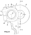
- 6A, 6B and 6C are a top plan view, an elevation side view, and an elevation front view, respectively, of a load cell device according to the invention
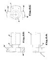
- fig. 7 is a top plan view of an end of the arrangement according to the invention.
- fig. 8 is an elevation side view of the end of fig. 7;
- fig. 9 is a cross-section view according to the line IX-IX in fig. 8;
- fig. 10 is an elevation side view from inside the loom, of the left suspension system onto which the arrangement of the invention is mounted;
- fig. 11 is an elevation side view of a left shoulder of the loom onto which the arrangement of the invention is mounted.
- a back rest C is mounted at each end thereof, in a manner known per se, onto supporting hub devices C 1 .
- each hub device C 1 has a fastening flange C 2 by means of which it is fixed, through fastening screws V 1 and V 2 , to the force-applying foot 1 of a torsional load cell.
- the force-applying foot 1 of the cell is substantially T-shaped: on the two arms 1a and 1b are obtained holes 1a' and 1b' in which screws V 1 and V 2 shall engage to fix the fastening flange C 2 .
- a cylindrical body 2 projects perpendicularly, for example having a diameter of 45 mm.
- a relief groove 3 is provided, into which measuring strain-gauges are mounted.
- the groove 3 has the advantage of representing a "protected" physical area into which the strain-gauges can be placed and, above all, of allowing to best exploit the deformability range of the strain-gauges themselves (the load conditions being equal, a stronger signal is obtained), however without compromising fatigue resistance of the same and of the load cell material.
- such groove has a reduced diameter, for example 30 mm.
- the strain-gauges have a full bridge connection to each other, which in addition to the higher signal/strain ratio, allows to compensate the undesired effects due to bending, traction and compression.
- the load cell according to the invention has been implemented through strain-gauges MM of the type J2A-06S11K350 (specific for transducers, and inexpensive) glued with cyanoacrylate adhesives, and balanced within a range of ⁇ 40 ⁇ V and powered by a 10-Volt supply.
- a tightening sleeve 4 is fixed, consisting of an anular tightening portion 4a - providing two jaws, mutually interlocking by means of a screw element 5 - and a thinner enveloping portion 4b, which preferably extends at least along the whole length of the cylindrical body 2.
- a flap or flange 6 from which an abutting pin projects perpendicularly, which is useful during the assembling step.
- a supporting bracket 8 capable of connecting the whole arrangement of the back rest to a suitable supporting kinetic mechanism of the loom (fig. 10).
- the tension of the warp yarns T (fig. 11) is applied onto the back rest C, then reaches the supporting structure of the weaving loom through the load cell, which is capable of reading the value thereof and of translating it into an electric signal.
- the axis of the back rest C is offset in respect of the central axis of the cylindrical body 2 of the load cell, respectively marked by projections O and O' in fig. 8.
- the electric signal coming from the torsional load cell is then fed and processed within a feedback loop capable of intervening correctly on the chain controls, in particular on the motors of the let-off motion cylinder and of the fabric-tensioning roller.
- An exemplary circuit of this type is shown in fig. 5.
- the signal coming from the load cell is fed into an amplifier (A) having the function of translating the signal into a range of values expected by a voltage-to-frequency converter.
- A an amplifier having the function of translating the signal into a range of values expected by a voltage-to-frequency converter.
- the amplifier due to the inevitable presence of a resistor-capacitor-type circuit, has an own time constant, which therefore already causes a first damping of the input signal.
- the signal is then processed by a voltage-to-frequency converter (V/F) which translates the analogical tension signal, coming from the amplifier, into a frequency modulated signal: the output in Hertz is proportional to the input in Volts.
- V/F voltage-to-frequency converter
- the frequency signal is then translated into a digital piece of information within a suitable microprocessor (MP): over a certain time interval the periods of the signal coming from the V/F converter are counted.
- MP microprocessor
- the sampling of the signal is not continuous, but repeated at constant time intervals. Since it is not dependent on the cycle period of the machine, it is called asynchronous: for example, it occurs every 10 ms, which is a sufficiently short period to prevent the signal from being misinterpreted.
- an "offset" for example the tare of the back rest
- the sign can be inverted, if necessary.
- the signal t coming from the RTC is compared against a preset reference voltage: the error obtained is examined both in its proportional part - used for major changes (for example at the starting of the loom) - and in its integral part - used to compensate the oscillations about the preset reference value; each of these two parts has an own associated coefficient of intervention: clearly, the value assigned to these parameters is important for the correct operation of the system.
- control unit is used to adjust warp beam drive and thus the tension of the warp yarns on the back rest, which provides a certain reaction in the load cell, which in turn produces a rectifying signal to be feedback-fed into the loop and so on, until convergence towards an optimal value is reached.
- fictitious warp-beam-releasing radius also called transmission ratio, i.e. the ratio of loom cycles to warp beam revolutions
- the Applicant was able to practically obtain an arrangement according to the invention which, by means of a single cell, made it possible to cover the whole range of possible tensions, from the lowest ones to the highest ones, estimated to be - in terms of the torsional moment on the cell - 20 ⁇ 770 Nm plus the torsional moment due to the mass of the back rest which, depending on the length of the back rest, is 24 ⁇ 116 Nm.
- the load cell always used and transferred a signal of a few mVolts correctly, which was subsequently suitably conditioned and amplified in the circuit described above. Also, detection reproducibility was excellent, with maximum deviation in the region of 1%.
Landscapes
- Engineering & Computer Science (AREA)
- Textile Engineering (AREA)
- Looms (AREA)
- Woven Fabrics (AREA)
- Spinning Or Twisting Of Yarns (AREA)
Applications Claiming Priority (2)
| Application Number | Priority Date | Filing Date | Title |
|---|---|---|---|
| IT000182A ITMI20030182A1 (it) | 2003-02-04 | 2003-02-04 | Disposizione di portafili perfezionata per un telaio tessile |
| ITMI20030182 | 2003-02-04 |
Publications (3)
| Publication Number | Publication Date |
|---|---|
| EP1445363A2 true EP1445363A2 (de) | 2004-08-11 |
| EP1445363A3 EP1445363A3 (de) | 2005-01-12 |
| EP1445363B1 EP1445363B1 (de) | 2008-02-27 |
Family
ID=32652459
Family Applications (1)
| Application Number | Title | Priority Date | Filing Date |
|---|---|---|---|
| EP04100319A Expired - Lifetime EP1445363B1 (de) | 2003-02-04 | 2004-01-29 | Anordnung des Streichbaums in einer Webmaschine |
Country Status (5)
| Country | Link |
|---|---|
| EP (1) | EP1445363B1 (de) |
| AT (1) | ATE387526T1 (de) |
| DE (1) | DE602004012004T2 (de) |
| ES (1) | ES2303022T3 (de) |
| IT (1) | ITMI20030182A1 (de) |
Cited By (1)
| Publication number | Priority date | Publication date | Assignee | Title |
|---|---|---|---|---|
| CN101070658B (zh) * | 2007-04-29 | 2010-11-17 | 江苏万工科技集团有限公司 | 喷气织机的打纬力矩自动调节装置 |
Families Citing this family (1)
| Publication number | Priority date | Publication date | Assignee | Title |
|---|---|---|---|---|
| CN110205738A (zh) * | 2019-07-16 | 2019-09-06 | 际华三五四二纺织有限公司 | 一种喷气织机后梁 |
Family Cites Families (6)
| Publication number | Priority date | Publication date | Assignee | Title |
|---|---|---|---|---|
| DE3528364A1 (de) * | 1985-08-07 | 1987-02-19 | Helmut Erb Elektr Messtechnik | Reaktionsdrehmomentaufnehmer und verfahren zu seiner messbereichsanpassung |
| CH681156A5 (de) * | 1989-05-02 | 1993-01-29 | Sulzer Ag | |
| JPH0551845A (ja) * | 1991-08-12 | 1993-03-02 | Toyota Autom Loom Works Ltd | 織機における経糸張力検出方法及び装置 |
| JP2534202Y2 (ja) * | 1991-12-13 | 1997-04-30 | 株式会社豊田自動織機製作所 | 織機における経糸張力検出装置 |
| IT1304112B1 (it) * | 1998-12-17 | 2001-03-07 | Vamatex Nuova Spa | Portafili a sospensione progressiva per telaio di tessitura |
| WO2002052082A1 (de) * | 2000-12-27 | 2002-07-04 | Textilma Ag | Vorrichtung zur überwachten zuführung von kettfäden zu einer web- oder ketten-wirkmaschine |
-
2003
- 2003-02-04 IT IT000182A patent/ITMI20030182A1/it unknown
-
2004
- 2004-01-29 EP EP04100319A patent/EP1445363B1/de not_active Expired - Lifetime
- 2004-01-29 DE DE602004012004T patent/DE602004012004T2/de not_active Expired - Lifetime
- 2004-01-29 ES ES04100319T patent/ES2303022T3/es not_active Expired - Lifetime
- 2004-01-29 AT AT04100319T patent/ATE387526T1/de not_active IP Right Cessation
Cited By (1)
| Publication number | Priority date | Publication date | Assignee | Title |
|---|---|---|---|---|
| CN101070658B (zh) * | 2007-04-29 | 2010-11-17 | 江苏万工科技集团有限公司 | 喷气织机的打纬力矩自动调节装置 |
Also Published As
| Publication number | Publication date |
|---|---|
| DE602004012004T2 (de) | 2009-02-26 |
| ITMI20030182A1 (it) | 2004-08-05 |
| EP1445363A3 (de) | 2005-01-12 |
| DE602004012004D1 (de) | 2008-04-10 |
| ATE387526T1 (de) | 2008-03-15 |
| ES2303022T3 (es) | 2008-08-01 |
| EP1445363B1 (de) | 2008-02-27 |
Similar Documents
| Publication | Publication Date | Title |
|---|---|---|
| EP1445363B1 (de) | Anordnung des Streichbaums in einer Webmaschine | |
| CN101105421A (zh) | 消极式凸轮开口机构的动态模拟振动测量装置 | |
| US4572243A (en) | System and apparatus for the measurement of the tension of textile fabrics in textile machines | |
| JPH0551845A (ja) | 織機における経糸張力検出方法及び装置 | |
| US5033400A (en) | Thread tensioning device for a sewing machine | |
| JP3535242B2 (ja) | 入口測定部材を有する練条機におけるスライバ用自動調節ドラフト装置 | |
| CN101033572B (zh) | 喷气织机的后梁力矩调节装置 | |
| EP0590725A1 (de) | Kettspannungskontrollvorrichtung für Webmaschinen | |
| JP5260961B2 (ja) | 開口装置および織機のための要素 | |
| CN1041951C (zh) | 测量织机经纱张力的改进装置 | |
| JPH02107926A (ja) | 電子秤 | |
| US4794802A (en) | Process and apparatus for measuring the warp tension in looms and the like | |
| EP0487126A1 (de) | Tragvorrichtung für den Streichbaum in einer Webmaschine | |
| EP0537111A1 (de) | Vorrichtung zum Detektieren der Kettenspannung in Webmaschinen | |
| JPH024134Y2 (de) | ||
| CN109844198B (zh) | 用于测量织机中经纱张力的测量设备和带有这种测量设备的织机 | |
| JPH1038722A (ja) | 糸のテンションセンサ | |
| SU280043A1 (ru) | Прибор для измерения сил инерции рабочего органа | |
| WO2022053321A1 (en) | Device and method for sensing a tension in a thread, and method for mounting a sensor unit | |
| CN120389569B (zh) | 一种用于步进电机共振的检测装置 | |
| CN121272628A (zh) | 织机经线张力动态稳定输出装置 | |
| SU164564A1 (ru) | Прибор для измерения натяжения нитей основы на шлихтовальных и других подобных машинах | |
| CN109355786B (zh) | 无梭织机摆动后梁 | |
| JP2003193353A (ja) | 織機の織物応力を測定する測定装置およびこの種の測定装置を備えた織機 | |
| JPH0351341Y2 (de) |
Legal Events
| Date | Code | Title | Description |
|---|---|---|---|
| PUAI | Public reference made under article 153(3) epc to a published international application that has entered the european phase |
Free format text: ORIGINAL CODE: 0009012 |
|
| AK | Designated contracting states |
Kind code of ref document: A2 Designated state(s): AT BE BG CH CY CZ DE DK EE ES FI FR GB GR HU IE IT LI LU MC NL PT RO SE SI SK TR |
|
| AX | Request for extension of the european patent |
Extension state: AL LT LV MK |
|
| PUAL | Search report despatched |
Free format text: ORIGINAL CODE: 0009013 |
|
| AK | Designated contracting states |
Kind code of ref document: A3 Designated state(s): AT BE BG CH CY CZ DE DK EE ES FI FR GB GR HU IE IT LI LU MC NL PT RO SE SI SK TR |
|
| AX | Request for extension of the european patent |
Extension state: AL LT LV MK |
|
| 17P | Request for examination filed |
Effective date: 20050620 |
|
| AKX | Designation fees paid |
Designated state(s): AT BE BG CH CY CZ DE DK EE ES FI FR GB GR HU IE IT LI LU MC NL PT RO SE SI SK TR |
|
| GRAP | Despatch of communication of intention to grant a patent |
Free format text: ORIGINAL CODE: EPIDOSNIGR1 |
|
| GRAS | Grant fee paid |
Free format text: ORIGINAL CODE: EPIDOSNIGR3 |
|
| GRAA | (expected) grant |
Free format text: ORIGINAL CODE: 0009210 |
|
| AK | Designated contracting states |
Kind code of ref document: B1 Designated state(s): AT BE BG CH CY CZ DE DK EE ES FI FR GB GR HU IE IT LI LU MC NL PT RO SE SI SK TR |
|
| REG | Reference to a national code |
Ref country code: GB Ref legal event code: FG4D |
|
| REG | Reference to a national code |
Ref country code: CH Ref legal event code: EP |
|
| REG | Reference to a national code |
Ref country code: IE Ref legal event code: FG4D |
|
| REF | Corresponds to: |
Ref document number: 602004012004 Country of ref document: DE Date of ref document: 20080410 Kind code of ref document: P |
|
| REG | Reference to a national code |
Ref country code: CH Ref legal event code: NV Representative=s name: PATENTANWAELTE SCHAAD, BALASS, MENZL & PARTNER AG |
|
| PG25 | Lapsed in a contracting state [announced via postgrant information from national office to epo] |
Ref country code: FI Free format text: LAPSE BECAUSE OF FAILURE TO SUBMIT A TRANSLATION OF THE DESCRIPTION OR TO PAY THE FEE WITHIN THE PRESCRIBED TIME-LIMIT Effective date: 20080227 |
|
| NLV1 | Nl: lapsed or annulled due to failure to fulfill the requirements of art. 29p and 29m of the patents act | ||
| REG | Reference to a national code |
Ref country code: ES Ref legal event code: FG2A Ref document number: 2303022 Country of ref document: ES Kind code of ref document: T3 |
|
| PG25 | Lapsed in a contracting state [announced via postgrant information from national office to epo] |
Ref country code: AT Free format text: LAPSE BECAUSE OF FAILURE TO SUBMIT A TRANSLATION OF THE DESCRIPTION OR TO PAY THE FEE WITHIN THE PRESCRIBED TIME-LIMIT Effective date: 20080227 |
|
| PG25 | Lapsed in a contracting state [announced via postgrant information from national office to epo] |
Ref country code: SI Free format text: LAPSE BECAUSE OF FAILURE TO SUBMIT A TRANSLATION OF THE DESCRIPTION OR TO PAY THE FEE WITHIN THE PRESCRIBED TIME-LIMIT Effective date: 20080227 |
|
| PG25 | Lapsed in a contracting state [announced via postgrant information from national office to epo] |
Ref country code: PT Free format text: LAPSE BECAUSE OF FAILURE TO SUBMIT A TRANSLATION OF THE DESCRIPTION OR TO PAY THE FEE WITHIN THE PRESCRIBED TIME-LIMIT Effective date: 20080721 Ref country code: SK Free format text: LAPSE BECAUSE OF FAILURE TO SUBMIT A TRANSLATION OF THE DESCRIPTION OR TO PAY THE FEE WITHIN THE PRESCRIBED TIME-LIMIT Effective date: 20080227 Ref country code: SE Free format text: LAPSE BECAUSE OF FAILURE TO SUBMIT A TRANSLATION OF THE DESCRIPTION OR TO PAY THE FEE WITHIN THE PRESCRIBED TIME-LIMIT Effective date: 20080527 Ref country code: NL Free format text: LAPSE BECAUSE OF FAILURE TO SUBMIT A TRANSLATION OF THE DESCRIPTION OR TO PAY THE FEE WITHIN THE PRESCRIBED TIME-LIMIT Effective date: 20080227 Ref country code: CZ Free format text: LAPSE BECAUSE OF FAILURE TO SUBMIT A TRANSLATION OF THE DESCRIPTION OR TO PAY THE FEE WITHIN THE PRESCRIBED TIME-LIMIT Effective date: 20080227 Ref country code: DK Free format text: LAPSE BECAUSE OF FAILURE TO SUBMIT A TRANSLATION OF THE DESCRIPTION OR TO PAY THE FEE WITHIN THE PRESCRIBED TIME-LIMIT Effective date: 20080227 |
|
| ET | Fr: translation filed | ||
| PG25 | Lapsed in a contracting state [announced via postgrant information from national office to epo] |
Ref country code: RO Free format text: LAPSE BECAUSE OF FAILURE TO SUBMIT A TRANSLATION OF THE DESCRIPTION OR TO PAY THE FEE WITHIN THE PRESCRIBED TIME-LIMIT Effective date: 20080227 |
|
| PLBE | No opposition filed within time limit |
Free format text: ORIGINAL CODE: 0009261 |
|
| STAA | Information on the status of an ep patent application or granted ep patent |
Free format text: STATUS: NO OPPOSITION FILED WITHIN TIME LIMIT |
|
| 26N | No opposition filed |
Effective date: 20081128 |
|
| PG25 | Lapsed in a contracting state [announced via postgrant information from national office to epo] |
Ref country code: EE Free format text: LAPSE BECAUSE OF FAILURE TO SUBMIT A TRANSLATION OF THE DESCRIPTION OR TO PAY THE FEE WITHIN THE PRESCRIBED TIME-LIMIT Effective date: 20080227 Ref country code: BG Free format text: LAPSE BECAUSE OF FAILURE TO SUBMIT A TRANSLATION OF THE DESCRIPTION OR TO PAY THE FEE WITHIN THE PRESCRIBED TIME-LIMIT Effective date: 20080527 |
|
| PGFP | Annual fee paid to national office [announced via postgrant information from national office to epo] |
Ref country code: ES Payment date: 20090108 Year of fee payment: 6 |
|
| PG25 | Lapsed in a contracting state [announced via postgrant information from national office to epo] |
Ref country code: CY Free format text: LAPSE BECAUSE OF FAILURE TO SUBMIT A TRANSLATION OF THE DESCRIPTION OR TO PAY THE FEE WITHIN THE PRESCRIBED TIME-LIMIT Effective date: 20080227 |
|
| PG25 | Lapsed in a contracting state [announced via postgrant information from national office to epo] |
Ref country code: MC Free format text: LAPSE BECAUSE OF NON-PAYMENT OF DUE FEES Effective date: 20090131 |
|
| GBPC | Gb: european patent ceased through non-payment of renewal fee |
Effective date: 20090129 |
|
| PGFP | Annual fee paid to national office [announced via postgrant information from national office to epo] |
Ref country code: FR Payment date: 20081219 Year of fee payment: 6 |
|
| PG25 | Lapsed in a contracting state [announced via postgrant information from national office to epo] |
Ref country code: GB Free format text: LAPSE BECAUSE OF NON-PAYMENT OF DUE FEES Effective date: 20090129 |
|
| PG25 | Lapsed in a contracting state [announced via postgrant information from national office to epo] |
Ref country code: IE Free format text: LAPSE BECAUSE OF NON-PAYMENT OF DUE FEES Effective date: 20090129 |
|
| REG | Reference to a national code |
Ref country code: FR Ref legal event code: ST Effective date: 20100930 |
|
| PG25 | Lapsed in a contracting state [announced via postgrant information from national office to epo] |
Ref country code: GR Free format text: LAPSE BECAUSE OF FAILURE TO SUBMIT A TRANSLATION OF THE DESCRIPTION OR TO PAY THE FEE WITHIN THE PRESCRIBED TIME-LIMIT Effective date: 20080528 Ref country code: FR Free format text: LAPSE BECAUSE OF NON-PAYMENT OF DUE FEES Effective date: 20100201 |
|
| REG | Reference to a national code |
Ref country code: ES Ref legal event code: FD2A Effective date: 20110401 |
|
| PG25 | Lapsed in a contracting state [announced via postgrant information from national office to epo] |
Ref country code: LU Free format text: LAPSE BECAUSE OF NON-PAYMENT OF DUE FEES Effective date: 20090129 |
|
| PG25 | Lapsed in a contracting state [announced via postgrant information from national office to epo] |
Ref country code: HU Free format text: LAPSE BECAUSE OF FAILURE TO SUBMIT A TRANSLATION OF THE DESCRIPTION OR TO PAY THE FEE WITHIN THE PRESCRIBED TIME-LIMIT Effective date: 20080828 |
|
| PG25 | Lapsed in a contracting state [announced via postgrant information from national office to epo] |
Ref country code: ES Free format text: LAPSE BECAUSE OF NON-PAYMENT OF DUE FEES Effective date: 20110322 |
|
| PG25 | Lapsed in a contracting state [announced via postgrant information from national office to epo] |
Ref country code: ES Free format text: LAPSE BECAUSE OF NON-PAYMENT OF DUE FEES Effective date: 20100130 |
|
| PG25 | Lapsed in a contracting state [announced via postgrant information from national office to epo] |
Ref country code: TR Free format text: LAPSE BECAUSE OF NON-PAYMENT OF DUE FEES Effective date: 20090129 |
|
| PGFP | Annual fee paid to national office [announced via postgrant information from national office to epo] |
Ref country code: CH Payment date: 20130123 Year of fee payment: 10 Ref country code: DE Payment date: 20130122 Year of fee payment: 10 |
|
| REG | Reference to a national code |
Ref country code: DE Ref legal event code: R119 Ref document number: 602004012004 Country of ref document: DE |
|
| REG | Reference to a national code |
Ref country code: CH Ref legal event code: PL |
|
| REG | Reference to a national code |
Ref country code: DE Ref legal event code: R119 Ref document number: 602004012004 Country of ref document: DE Effective date: 20140801 |
|
| PG25 | Lapsed in a contracting state [announced via postgrant information from national office to epo] |
Ref country code: CH Free format text: LAPSE BECAUSE OF NON-PAYMENT OF DUE FEES Effective date: 20140131 Ref country code: DE Free format text: LAPSE BECAUSE OF NON-PAYMENT OF DUE FEES Effective date: 20140801 Ref country code: LI Free format text: LAPSE BECAUSE OF NON-PAYMENT OF DUE FEES Effective date: 20140131 |
|
| PGFP | Annual fee paid to national office [announced via postgrant information from national office to epo] |
Ref country code: IT Payment date: 20221221 Year of fee payment: 20 Ref country code: BE Payment date: 20230119 Year of fee payment: 20 |
|
| REG | Reference to a national code |
Ref country code: BE Ref legal event code: MK Effective date: 20240129 |