EP1447631A2 - Entspannungsventil - Google Patents
Entspannungsventil Download PDFInfo
- Publication number
- EP1447631A2 EP1447631A2 EP04012066A EP04012066A EP1447631A2 EP 1447631 A2 EP1447631 A2 EP 1447631A2 EP 04012066 A EP04012066 A EP 04012066A EP 04012066 A EP04012066 A EP 04012066A EP 1447631 A2 EP1447631 A2 EP 1447631A2
- Authority
- EP
- European Patent Office
- Prior art keywords
- expansion valve
- valve body
- valve
- passage
- mounting
- Prior art date
- Legal status (The legal status is an assumption and is not a legal conclusion. Google has not performed a legal analysis and makes no representation as to the accuracy of the status listed.)
- Withdrawn
Links
Images


Classifications
-
- F—MECHANICAL ENGINEERING; LIGHTING; HEATING; WEAPONS; BLASTING
- F25—REFRIGERATION OR COOLING; COMBINED HEATING AND REFRIGERATION SYSTEMS; HEAT PUMP SYSTEMS; MANUFACTURE OR STORAGE OF ICE; LIQUEFACTION SOLIDIFICATION OF GASES
- F25B—REFRIGERATION MACHINES, PLANTS OR SYSTEMS; COMBINED HEATING AND REFRIGERATION SYSTEMS; HEAT PUMP SYSTEMS
- F25B41/00—Fluid-circulation arrangements
- F25B41/30—Expansion means; Dispositions thereof
- F25B41/31—Expansion valves
- F25B41/33—Expansion valves with the valve member being actuated by the fluid pressure, e.g. by the pressure of the refrigerant
- F25B41/335—Expansion valves with the valve member being actuated by the fluid pressure, e.g. by the pressure of the refrigerant via diaphragms
-
- F—MECHANICAL ENGINEERING; LIGHTING; HEATING; WEAPONS; BLASTING
- F25—REFRIGERATION OR COOLING; COMBINED HEATING AND REFRIGERATION SYSTEMS; HEAT PUMP SYSTEMS; MANUFACTURE OR STORAGE OF ICE; LIQUEFACTION SOLIDIFICATION OF GASES
- F25B—REFRIGERATION MACHINES, PLANTS OR SYSTEMS; COMBINED HEATING AND REFRIGERATION SYSTEMS; HEAT PUMP SYSTEMS
- F25B41/00—Fluid-circulation arrangements
- F25B41/30—Expansion means; Dispositions thereof
- F25B41/31—Expansion valves
-
- F—MECHANICAL ENGINEERING; LIGHTING; HEATING; WEAPONS; BLASTING
- F25—REFRIGERATION OR COOLING; COMBINED HEATING AND REFRIGERATION SYSTEMS; HEAT PUMP SYSTEMS; MANUFACTURE OR STORAGE OF ICE; LIQUEFACTION SOLIDIFICATION OF GASES
- F25B—REFRIGERATION MACHINES, PLANTS OR SYSTEMS; COMBINED HEATING AND REFRIGERATION SYSTEMS; HEAT PUMP SYSTEMS
- F25B2341/00—Details of ejectors not being used as compression device; Details of flow restrictors or expansion valves
- F25B2341/06—Details of flow restrictors or expansion valves
- F25B2341/068—Expansion valves combined with a sensor
- F25B2341/0683—Expansion valves combined with a sensor the sensor is disposed in the suction line and influenced by the temperature or the pressure of the suction gas
-
- F—MECHANICAL ENGINEERING; LIGHTING; HEATING; WEAPONS; BLASTING
- F25—REFRIGERATION OR COOLING; COMBINED HEATING AND REFRIGERATION SYSTEMS; HEAT PUMP SYSTEMS; MANUFACTURE OR STORAGE OF ICE; LIQUEFACTION SOLIDIFICATION OF GASES
- F25B—REFRIGERATION MACHINES, PLANTS OR SYSTEMS; COMBINED HEATING AND REFRIGERATION SYSTEMS; HEAT PUMP SYSTEMS
- F25B2500/00—Problems to be solved
- F25B2500/05—Cost reduction
-
- F—MECHANICAL ENGINEERING; LIGHTING; HEATING; WEAPONS; BLASTING
- F25—REFRIGERATION OR COOLING; COMBINED HEATING AND REFRIGERATION SYSTEMS; HEAT PUMP SYSTEMS; MANUFACTURE OR STORAGE OF ICE; LIQUEFACTION SOLIDIFICATION OF GASES
- F25B—REFRIGERATION MACHINES, PLANTS OR SYSTEMS; COMBINED HEATING AND REFRIGERATION SYSTEMS; HEAT PUMP SYSTEMS
- F25B2500/00—Problems to be solved
- F25B2500/32—Weight
Definitions
- the present invention relates to an expansion valve for controlling the flow rate of a refrigerant to be supplied to an evaporator in a refrigeration cycle of a refrigerator, an air conditioning device and so on.
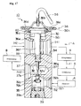
- FIG. 17 shows a vertical cross-sectional view of a widely used prior art expansion valve with an outline of the refrigeration cycle.
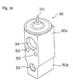
- FIG. 18 is a schematic view of the valve body in the expansion valve, and
- FIG. 19 is a front view of the expansion valve viewed from direction A of FIG. 17.
- the expansion valve 10 comprises a valve body 30 made of aluminum alloy and having a substantially prismatic shape, to which are formed a first passage 32 of a refrigerant pipe 11 in the refrigeration cycle mounted in the portion from the refrigerant exit of a condenser 5 through a receiver 6 toward the refrigerant entrance of an evaporator 8 through which a liquid-phase refrigerant travels, and a second passage 34 of the refrigerant pipe 11 mounted in the portion from the refrigerant exit of the evaporator 8 toward the refrigerant entrance of a compressor 4 through which a gas-phase refrigerant travels.
- the passages are formed so that one passage is positioned above the other passage with a distance in between.
- reference number 50 shows bolt inserting holes for mounting the expansion valve 10.
- first passage 32 On the first passage 32 is formed an orifice 32a where adiabatic expansion of the liquid-phase refrigerant supplied from the refrigerant exit of the receiver 6 is to be performed.
- a valve seat On the entrance side of the orifice 32a or upper stream side of the first passage is formed a valve seat, and a spherical valve means 32b supported by the valve member 32c from the upper stream side is positioned on the valve seat.
- the valve member 32c is fixed to the valve means by welding, and positioned between a biasing means 32d of a compression coil-spring and the like, thereby transmitting the bias force of the biasing means 32d to the valve means 32b, and as a result, biasing the valve means 32b toward the direction approaching the valve seat.
- the first passage 32 to which the liquid-phase refrigerant from the receiver 6 is introduced acts as the passage for the liquid-phase refrigerant, comprising an entrance port 321 connected to the receiver 6, and a valve chamber 35 connected to the entrance port 321.
- An exit port 322 is connected to the evaporator 8.
- the valve chamber 35 is a chamber with a bottom formed coaxially with the orifice 32a, and is sealed by a plug 39.
- the plug 39 is equipped with an o-ring 39a.
- valve body 30 is equipped with a small radius hole 37 and a large radius hole 38, which is larger than the hole 37, which penetrates through the second passage 34 and are positioned coaxial to the orifice 32a, so as to provide driving force to the valve means 32b according to the exit temperature of the evaporator 8, and on the upper end of the valve body 30 is formed a screw hole 361 to which a power element portion 36 acting as a heat sensing portion is fixed.
- valve body 30 includes a narrow portion 30b having a thin width whose width size W 2 is reduced (narrowed) compared to the width size W 1 of the portion where the bolt holes 50 exist, at the lower portion corresponding to the first passage 32 which is opposite to the upper portion where the power element portion 36 is to be mounted.
- the narrow portion contributes to lighten the weight and to reduce the cost of the parts used for the valve body 30.
- the base-shape material (material formed to have the basic shape) of the valve body 30 is manufactured by an extrusion process of an aluminum alloy for example, and the bolt holes 50 are formed by a following drilling process.
- the power element portion 36 comprises a diaphragm 36a made of stainless steel, an upper cover 36d and a lower cover 36h welded to each other with the diaphragm 36a positioned in between so as to each define an upper pressure housing 36b and a lower pressure housing 36c forming two sealed housing on the upper and lower areas of the diaphragm 36a, and a sealed tube 36i for sealing a predetermined refrigerant working as a diaphragm driving liquid into the upper pressure housing 36b, wherein the lower cover 36h is screwed onto the screw hole 361 with a packing 40.
- the lower pressure housing 36c is communicated to the second passage 34 through a pressure-equalizing hole 36e formed coaxial to the center axis of the orifice 32a.
- reference number 342 represents an entrance port from which the refrigerant transmitted from the evaporator 8 enters
- 341 represents an exit port from which the refrigerant transmitted to the compressor 4 exits.
- an aluminum heat sensing shaft 36f positioned slidably inside the large radius hole 38 penetrating the second passage 34, so as to transmit the refrigerant exit temperature of the evaporator 8 to the lower pressure housing 36c and to slide inside the large radius hole 38 in correspondence to the displacement of the diaphragm 36a accompanied by the difference in pressure between the lower pressure chamber 36c and the upper pressure chamber 36b in order to provide drive force, and a stainless steel operating shaft 37f having a smaller diameter than the heat sensing shaft 36f is positioned slidably inside the small radius hole 37 for pressing the valve means 32b against the elastic force of the biasing means 32d in correspondence to the displacement of the heat sensing shaft 36f, wherein the heat sensing shaft 36f is equipped with a sealing member, for example, an o-ring 36g, so as to secure the seal between the first passage 32 and the second passage 34.
- a sealing member for example, an o-ring 36g
- the upper end of the heat sensing shaft 36f contacts to the lower surface of the diaphragm 36a as the receiving portion of the diaphragm 36a, the lower end of the heat sensing shaft 36f contacts to the upper end of the operating shaft 37f, and the lower end of the operating shaft 37f contacts to the valve means 32b, wherein the heat sensing shaft 36f together with the operating shaft 37f constitute a valve drive shaft.
- the valve drive shaft extending from the lower surface of the diaphragm 36a to the orifice 32a of the first passage 32 is positioned coaxially inside the pressure-equalizing hole 36e.
- a portion 37e of the operating shaft 37f is formed narrower than the inner diameter of the orifice 32a, which penetrates through the orifice 32a, and the refrigerant passes through the orifice 32a.
- a known diaphragm drive liquid is filled inside the upper pressure housing 36b of the pressure housing 36d, and through the diaphragm 36a and the valve drive shaft exposed to the second passage 34 and the pressure equalizing hole 36e communicated to the second passage 34, the heat of the refrigerant vapor travelling through the second passage 34 from the refrigerant exit of the evaporator 8 is transmitted to the diaphragm drive liquid.
- the diaphragm drive liquid inside the upper pressure housing 36b turns into gas, the pressure thereof being loaded to the upper surface of the diaphragm 36a.
- the diaphragm 36a is displaced to the vertical direction according to the difference between the pressure of the diaphragm drive gas loaded to the upper surface thereof and the pressure loaded to the lower surface thereof.
- the vertical displacement of the center are of the diaphragm 36a is transmitted to the valve means 32b through the valve drive shaft, which moves the valve means 32b closer to or away from the valve seat of the orifice 32a. As a result, the flow rate of the refrigerant is controlled.
- the temperature of the low-pressure gas-phase refrigerant sent out from the exit of the evaporator 8 is transmitted to the upper pressure housing 36b, and according to the temperature, the pressure inside the upper pressure housing 36b is changed.
- the exit temperature of the evaporator 8 rises, in other words, when the heat load of the evaporator is increased, the pressure inside the upper pressure housing 86b is raised, and correspondingly, the heat sensing shaft 36f or valve drive shaft is driven to the downward direction, pushing down the valve means 32b.
- the opening of the orifice 32a is widened. This increases the amount of refrigerant being supplied to the evaporator 8, and lowers the temperature of the evaporator 8.
- valve means 32b is driven to the opposite direction, narrowing the opening of the orifice 32a, reducing the amount of refrigerant being supplied to the evaporator, and raises the temperature of the evaporator 8.
- FIG. 20 is a view explaining the mounting structure thereof, and in the drawing, a mounting member 60 is formed to have a plate-like shape, supporting two pipes 62 and 64.
- the pipe 62 is a pipe communicated to the compressor 4, and a tip portion 62a thereof is inserted to a port 341. In such state, a seal is formed between the pipe and the port by a seal ring 62b.
- the second pipe 64 is communicated to the receiver 6, and a tip portion 64a thereof is inserted to a port 321 through a seal 64b.
- a mounting member 70 is formed to have a plate shape, supporting two pipes 72 and 74.
- the pipe 72 is communicated to the exit of the evaporator 8, and a tip portion 72a thereof is inserted to a port 342 through a seal 72b.
- the pipe 74 is communicated to the entrance of the evaporator 8, and a tip portion 74a thereof is inserted to a port 322 through a seal 74b.
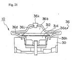
- a plug body 36k may be used to seal the predetermined refrigerant as shown in FIG. 21 instead of using the sealed tube 36i as shown in FIG. 17.
- a stainless steel plug body 36k may be inserted to a hole 36j formed on the upper cover 36d made of stainless steel so as to cover the hole, and the plug body 36k may be fixed to the hole 36j by welding.
- the operation for controlling the flow rate of the refrigerant by the valve is similar to that of FIG. 17, so FIG. 21 only shows the area related to the power element portion 36.
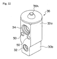
- FIG. 22 shows the schematic view of the valve body similar to FIG. 18 of the expansion valve but when the seal is performed by the plug body 36k, and the same reference numbers show the same components. In FIGS. 18 and 19, the sealed tube 36i is omitted.
- the bolt holes 50 for mounting the expansion valve is formed as a penetrating hole on the inner side of the both side surfaces 30a of the valve body 30 in the expansion valve.
- the bolt holes 50 must be formed in correspondence to the interval between the bolt holes 66 formed on the mounting member 60, and when the interval or pitch between the bolt holes formed on the mounting member are wide, the width size W 1 of the valve body 30 must also be widened. In this case, even if a narrow portion 30b having a width size of W 2 is formed on the lower portion of the valve body 30 corresponding to the first passage 32, there remains a problem that the cut-down on cost and weight may not be achieved.
- the present invention aims at solving the above-mentioned problems, and the object is to provide an expansion valve which is capable of introducing bolt holes having necessary intervals, without having to increase the width size of the valve body greatly, even when the intervals of the bolt holes for mounting the expansion valve formed on the inner side of both side surfaces of the valve body is widened.
- the present invention aims at providing an expansion valve with a structure realizing the further cutback on the weight and material cost of the valve body.
- the present invention aims at providing an expansion valve having increased degree of freedom in mounting the piping to be connected to the expansion valve, enabling easy mounting of the piping to the expansion valve, and at the same time, having improved its workability.
- the present invention provides an expansion valve comprising a valve body, a valve means for adjusting the flow rate of the refrigerant to be sent out to an evaporator, and a power element portion for driving said valve means according to the temperature of said refrigerant to be sent out to a compressor from said evaporator, wherein said valve body includes protruding portions formed integrally to the side surface of said valve body.
- said protruding portions are formed to positions corresponding to where penetrating holes for mounting the expansion valve are to be formed.
- the embodiment of the expansion valve according to the present invention characterizes in that said penetrating holes are formed inside said valve body at positions separated from said protruding portions by a predetermined distance.
- expansion valve according to the present invention is characterized in that said penetrating holes are formed on said protruding portions.
- the present invention relates to an expansion valve comprising a valve body, a valve means for adjusting the flow rate of a refrigerant traveling through a first passage formed inside said valve body from a condenser toward an evaporator, and a power element portion for driving said valve means according to the temperature of the refrigerant traveling through a second passage formed inside said valve body from said evaporator toward a compressor, wherein said expansion valve includes protruding portions formed integrally to the side surfaces of said valve body corresponding to penetrating holes formed on said valve body for mounting the expansion valve.
- said valve body comprises a first narrow portion where the lower portion of the valve body opposite to the upper portion to which said power element portion is to be mounted is formed to have a narrow width, and a second narrow portion where the area of the valve body between said first narrow portion and said protruding portion is formed to have a narrow width.
- the valve body includes a third narrow portion where the area of said valve body between said protruding portion and said power element portion is formed to have a narrow width.
- the present expansion valve is characterized in that a mounting hole for fixing a pipe mounting member is formed to said protruding portions.
- the present expansion valve comprises a prismatic valve body, a valve means for adjusting the flow rate of a refrigerant to be transmitted to an evaporator, and a power element portion for driving said valve means according to the temperature of the refrigerant transmitted from said evaporator to a compressor, wherein said valve body comprises prismatic projection formed integrally to the side surface of said valve body.
- the present expansion valve is characterized in that a mounting hole for fixing the pipe mounting member is formed to said projection.
- the expansion valve of the present invention having the above-mentioned structure is formed to have protruding portions on the side surface of the valve body. Therefore, the position of the bolt mounting holes may be determined freely.
- the expansion valve of the present invention comprises a plurality of narrow portions formed on the valve body, so the cost for material and parts of the expansion valve may be reduced, even when the protruding portions are formed.
- the expansion valve of the present invention enables to increase the degree of freedom in mounting the piping to the expansion valve, and the mounting of the piping is simplified and the workability is increased.
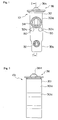
- FIG. 1 is a front view of an expansion valve 101 showing one embodiment of the expansion valve according to the present invention
- FIG. 2 is a side view thereof
- FIG. 3 is a schematic view of the expansion valve 101 omitting the interior structure
- FIG. 4 is a cross-sectional view taken at line I-I' of FIG. 1, omitting the refrigeration cycle.
- the expansion valve 101 shown in FIGS. 1-4 only differ from the prior art expansion valve 10 in that a protruding portion 301c is formed on the side surfaces 301a of the valve body 301.
- the other structures and operations are the same as the expansion valve 10 of the prior art, so the explanation thereof are omitted.
- the protruding portions 301c are formed integrally on the side surfaces 301c of the valve body 301, in a position corresponding to the where the penetrating mounting holes 50 of the valve body 301 will be formed.
- FIG. 5 is a schematic view showing the embodiment where a sealed tube 36i is used for the power element portion 36, and the same reference numbers as FIG. 4 refer to the same components.
- the base-shape material of the valve body 301 is formed by an extrusion process.
- the protruding portions 301c of the body are formed integrally when manufacturing the base-shape material.
- the penetrating holes 50 are formed by drilling holes to positions on the protruding portion 301c having a predetermined interval.
- FIG. 6 is a front view showing the case where penetrating holes 50 are formed at positions on the protruding portions 301c.
- penetrating holes 50 having predetermined intervals may also be formed simultaneously when manufacturing the base-shape material together with the protruding portions 301c, so as to omit the following drilling process. Moreover, the penetrating holes 50 may also be formed simultaneously by the hollow extrusion process together with a second passage penetrating the valve body 301 positioned parallel to the holes 50.
- protruding portions 301c are formed on the valve body 301 of the expansion valve so as to increase the degree of freedom in the position to which penetrating holes 50 may be formed. If, however, the cost of parts are increased by forming the above-mentioned protruding portions, then the cost of parts may be reduced by forming a narrow portion on plurality of positions on the valve body in the present expansion valve.
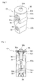
- FIG. 7 is a front view showing another embodiment of the expansion valve according to the present invention, wherein narrow portions are formed on a plurality of areas in the valve body of the expansion valve, and FIG. 8 is a side view thereof.
- the same reference numbers as used in the expansion valve of FIGS. 1 through 4 refer to either the same or equivalent components, and in the expansion valve 101' , narrow portions 30b (hereinafter called the first narrow portion) formed on the lower portion opposite to said upper portion of the valve body 301 where the power element portion 36 is to be mounted is formed, together with second narrow portions 301d.
- the second narrow portions 301d are formed on the area between the protruding portions 301c and a flat area 301f continuing from the first narrow portion 30b.
- third narrow portions 301e are formed between the power element portion 36 and the protruding portions 301c, continuing to the flat areas 301g of the side surfaces 301a.
- the second narrow portion 301d and the third narrow portion 301e may be formed.
- a plurality of narrow portions are formed to the valve body by the formation of the second narrow portions 301d and/or the third narrow portions 301e together with the first narrow portions 30b. Even if the cost of parts are increased by the formation of the protruding portions 301c, the cost and the weight may be reduced greatly by the formation of plurality of narrow portions. Moreover, the formation of the narrow portions by hollow extrusion process together with the protruding portions enable the achievement of providing an expansion valve having a greatly reduced manufacturing cost, since the portions may be formed simultaneously with the manufacturing of the base-shaped material.
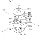
- FIG. 9 shows an embodiment of an expansion valve 102 according to the above case, by a schematic view omitting its internal structure.
- FIG. 10 is a front view taken from direction arrow R of FIG. 9, and
- FIG. 11 is a side view taken from direction arrow R' of FIG. 9.
- the expansion valve 102 is similar to the expansion valve 101 shown in FIGS. 1 through 3, except for protruding portions 302b and 302b' formed on the valve body 302 and mounting holes 51 formed on said protruding portions. Therefore, the same and similar portions of the expansion valve are marked by the same reference numbers, and the explanation thereof are omitted.
- the protruding portions 302b and 302b' are formed integrally to the side surface 302a of the valve body 302 by a hollow extrusion.
- the extrusion process is performed toward the direction parallel to the refrigerant passage by use of an aluminum alloy and the like.
- protruding portions 302b, 302b' and a concave portion 302c positioned between said protruding portions are formed integrally when manufacturing the base-shape material.
- the material is cut to an appropriate length as the valve body 302.
- the first passage 32, the second passage 34 and the penetrating holes 50 are formed to the predetermined positions respectively by a hole forming process.
- the mounting holes 51 are formed by a hole forming process to approximately the center area of the protruding portions 302b and 302b'.
- the mounting holes 51 may also be formed by a screwing process.
- the protruding portions 302b and 302b', the penetrating holes 50, the second passage 34 and the mounting holes 51 may also be formed simultaneously by a hollow extrusion process of an aluminum alloy and the like.
- the first passage 32 is formed by a hole forming process after the valve body 302 is cut. Further, a screwing process may be performed to the mounting holes 51.
- FIG. 9 shows the case where the protruding portions 302b and 302b' are formed to have the same length as the width of the side surface 302a of the valve body 302.
- the two protruding portions may also be cut to an appropriate length after being formed.
- the side surface of the valve body 302 having been removed of the two protruding portions may be utilized, for example, as a mounting space of the expansion valve 102.
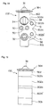
- FIG. 12 shows an embodiment of the expansion valve according to the present invention, wherein the expansion valve according to the embodiment shown in FIG. 9 is connected to the piping through the mounting holes 51.
- the same reference numbers as FIG. 9 show either the same or equivalent components.
- numbers 52 and 53 show plate-like pipe mounting members, and the pipe mounting members 53 and 52 comprise penetrating holes 32' and 51' each corresponding to the first passage 32 and the mounting hole 51, and penetrating holes 34' and 51' each corresponding to the second passage 34 and the mounting hole 51, respectively.
- the predetermined piping corresponding to each refrigerant passage (not shown) is connected at its end portion to the first passage 32 and the second passage 34 respectively through penetrating holes 32' and 34', as similar to the prior art.
- a bolt (not shown) is inserted to the mounting holes 51 through penetrating holes 51' corresponding to each mounting hole, and the bolts are either fixed to the mounting holes 51, or screwed to the screw portion of the mounting holes 51.
- the mounting member 53 is positioned so as to cover the first passage 32 and the mounting hole 51
- the mounting member 52 is fixed to cover the second passage 34 and the mounting hole 51 of the expansion valve 102, thereby supporting the predetermined piping.
- the holes marked 58 in FIGS. 9 and 10 are holes for inserting the positioning pins of mounting members 52 and 53, which can also be omitted.
- the piping to be connected to the first passage 32 and the second passage 34 may be mounted appropriately by the mounting members 52 and 53 to the expansion valve 102 fixed to a predetermined position, for example to the evaporator, by the penetrating holes 50.
- the degree of freedom in positioning the piping is increased, the fixing operation of the piping to an expansion valve for air-conditioning devices in vehicles which allow only small working space and limited mounting space may be eased, and therefore, the working condition of the mounting of pipes may be improved.
- the shape of the protruding portions, where the mounting holes for the pipe mounting member are to be formed is not limited to the shape of the embodiment shown in FIG. 9, but may be formed to have a prismatic projection.
- FIG. 13 shows another embodiment of the expansion valve according to the present invention with prismatic shaped protruding portions, wherein FIG. 13 is a schematic view omitting the internal structure thereof, FIG. 14 is a front view taken from direction arrow R of FIG. 13, and FIG. 15 is a side view taken from direction arrow R' of FIG. 13.
- the internal structure of the expansion valve is the same as that of FIG. 1.
- the expansion valve 103 of FIGS. 13 - 15 only differ from the embodiment of FIG. 9 in the shape of the valve body 303, and the other components are the same.
- the same or equivalent portions are marked by the same reference numbers, and the explanation thereof are omitted.
- the valve body 303 of the expansion valve 103 comprises a first passage 32, a second passage 34 and penetrating holes 50.
- the body further comprises a prismatic-shaped body portion 304 and a prismatic-shaped projection 305 formed integrally thereto, wherein mounting holes 54 and 55 each corresponding to the first passage 32 and the second passage 34 are formed on the projection 305.
- the body portion 304 is formed integrally with the projection 305 as the valve body 303 by an extrusion molding performed to the direction crossing said each refrigerant passages at right angles.
- the extrusion molding is performed by molding, for example, an aluminum alloy.
- the body portion 304 and the projection 305 may be formed integrally at the time of manufacture of the base-shape material.
- the material is cut to an appropriate length as the valve body 303, and the first passage 32, the second passage 34 and the penetrating holes 50 are formed to the body portion 304 by hole processing.
- mounting holes 54 and 55 are formed respectively to their predetermined positions on the projection 305 by hole processing.
- the mounting holes 54 and 55 may also be formed by screw processing.
- the valve body 302 and 303 are each assembled with a power element portion 36K, and with the internal structure formed thereto, they become expansion valves 102 and 103.
- FIG. 16 shows an embodiment of the present expansion valve wherein pipes are connected to the expansion valve according to the embodiment shown in FIG. 13 through mounting holes 54 and 55.
- the same reference numbers as FIG. 13 refer to either the same or equivalent components.
- reference numbers 56 and 57 show plate-like pipe mounting members.
- the pipe mounting member 56 and the pipe mounting member 57 are equipped with penetrating holes 32' and 54' each corresponding to the first passage 32 and the mounting hole 54, and penetrating holes 34' and 55' corresponding to the second passage 34 and the mounting hole 55, respectively.
- the predetermined pipes (not shown) corresponding to each of the refrigerant passages are connected at its tip portion through the penetrating holes 32' and 34' to each refrigerant passage, similarly as with the prior art.
- bolts are inserted to mounting holes 54 and 55 through penetrating holes 54' and 55' corresponding to each mounting hole, so as to be fixed to the mounting holes 54 and 55, or to be screwed onto the screw portion of the mounting holes 54 and 55.
- the mounting member 56 is fixed to the expansion valve 103 so as to cover the first passage 32 and the mounting hole 54
- the mounting member 57 is fixed to the expansion valve 103 so as to cover the second passage 34 and the mounting hole 55, thereby supporting predetermined pipes respectively.
- reference number 58 in FIGS. 13 and 14 show holes for inserting positioning pins of mounting members 56 and 57, which may be omitted.
- the pipes to be connected to the first passage 32 and the second passage 34 may be positioned appropriately against the expansion valve 103, fixed through the penetrating holes 50 to a predetermined position, by use of mounting members 56 and 57.
- the degree of freedom in positioning the piping is increased, and the mounting and positioning of the piping to an expansion valve for air-conditioning devices in vehicles which allow only small working space and limited mounting space may be eased.
- the degree of protrusion of the protruding portions or the projection may be determined to appropriate sizes according to need.
- the degree of protrusion may be increased by increasing the depth of the concave portion of the protruding portion.
- the expansion valve according to the present invention include protruding portions formed integrally to the side surfaces of the valve body in the expansion valve, which enable to provide a large degree of freedom in the positioning of the penetrating mounting holes to be formed on the valve body.
- the present expansion valve not only the above-mentioned protruding portions but also a plurality of narrow portions may be formed. This enables to decrease the manufacturing cost of the expansion valve, and at the same time, enables to reduce the size and lighten the weight of the expansion valve.
- the degree of freedom in the connecting of pipes to the expansion valve will be increased, the mounting operation thereof may be simplified, and the working performance as a whole may be improved.
Landscapes
- Engineering & Computer Science (AREA)
- Physics & Mathematics (AREA)
- Mechanical Engineering (AREA)
- Thermal Sciences (AREA)
- General Engineering & Computer Science (AREA)
- Fluid Mechanics (AREA)
- Temperature-Responsive Valves (AREA)
- Air-Conditioning For Vehicles (AREA)
- Valve Housings (AREA)
Applications Claiming Priority (5)
| Application Number | Priority Date | Filing Date | Title |
|---|---|---|---|
| JP6835298 | 1998-03-18 | ||
| JP6835298 | 1998-03-18 | ||
| JP10231452A JPH11325660A (ja) | 1998-03-18 | 1998-08-18 | 膨張弁 |
| JP23145298 | 1998-08-18 | ||
| EP99102072A EP0943878B1 (de) | 1998-03-18 | 1999-02-02 | Entspannungsventil |
Related Parent Applications (1)
| Application Number | Title | Priority Date | Filing Date |
|---|---|---|---|
| EP99102072A Division EP0943878B1 (de) | 1998-03-18 | 1999-02-02 | Entspannungsventil |
Publications (2)
| Publication Number | Publication Date |
|---|---|
| EP1447631A2 true EP1447631A2 (de) | 2004-08-18 |
| EP1447631A3 EP1447631A3 (de) | 2005-03-02 |
Family
ID=26409580
Family Applications (2)
| Application Number | Title | Priority Date | Filing Date |
|---|---|---|---|
| EP99102072A Expired - Lifetime EP0943878B1 (de) | 1998-03-18 | 1999-02-02 | Entspannungsventil |
| EP04012066A Withdrawn EP1447631A3 (de) | 1998-03-18 | 1999-02-02 | Entspannungsventil |
Family Applications Before (1)
| Application Number | Title | Priority Date | Filing Date |
|---|---|---|---|
| EP99102072A Expired - Lifetime EP0943878B1 (de) | 1998-03-18 | 1999-02-02 | Entspannungsventil |
Country Status (5)
| Country | Link |
|---|---|
| US (4) | US6241157B1 (de) |
| EP (2) | EP0943878B1 (de) |
| JP (1) | JPH11325660A (de) |
| KR (1) | KR19990077448A (de) |
| DE (1) | DE69924662T2 (de) |
Cited By (1)
| Publication number | Priority date | Publication date | Assignee | Title |
|---|---|---|---|---|
| CN102410677A (zh) * | 2010-09-17 | 2012-04-11 | 株式会社不二工机 | 膨胀阀的向制冷循环安装的安装结构 |
Families Citing this family (31)
| Publication number | Priority date | Publication date | Assignee | Title |
|---|---|---|---|---|
| JP3998887B2 (ja) * | 2000-03-02 | 2007-10-31 | 株式会社不二工機 | 膨張弁 |
| US6401470B1 (en) * | 2000-09-14 | 2002-06-11 | Xdx, Llc | Expansion device for vapor compression system |
| US6915648B2 (en) * | 2000-09-14 | 2005-07-12 | Xdx Inc. | Vapor compression systems, expansion devices, flow-regulating members, and vehicles, and methods for using vapor compression systems |
| US6857281B2 (en) * | 2000-09-14 | 2005-02-22 | Xdx, Llc | Expansion device for vapor compression system |
| EP1195546B1 (de) | 2000-10-03 | 2004-09-29 | Kabushiki Kaisha Kobe Seiko Sho | Ventilvorrichtung |
| JP2004053060A (ja) * | 2002-07-17 | 2004-02-19 | Fuji Koki Corp | 膨張弁 |
| USD498516S1 (en) | 2003-05-30 | 2004-11-16 | Fujikoki Corporation | Expansion valve |
| USD502252S1 (en) * | 2003-05-30 | 2005-02-22 | Fujikoki Corporation | Expansion valve |
| USD504714S1 (en) * | 2003-05-30 | 2005-05-03 | Fujikoki Corporation | Expansion valve |
| USD505183S1 (en) * | 2003-05-30 | 2005-05-17 | Fujikoki Corporation | Expansion valve |
| JP3899055B2 (ja) * | 2003-07-23 | 2007-03-28 | 株式会社テージーケー | 膨張弁 |
| US7089761B2 (en) * | 2004-01-08 | 2006-08-15 | Parker-Hannifin Corporation | Expansion valve with mounting bracket |
| JP2005226940A (ja) * | 2004-02-13 | 2005-08-25 | Fuji Koki Corp | 膨張弁 |
| US20060080999A1 (en) * | 2004-10-20 | 2006-04-20 | Behr Gmbh & Co. | Air conditioning system expansion valve |
| USD529990S1 (en) * | 2004-12-09 | 2006-10-10 | Fujikoki Corporation | Expansion valve |
| USD532080S1 (en) * | 2004-12-09 | 2006-11-14 | Fujikoki Corporation | Expansion valve |
| DE102009050882A1 (de) * | 2009-10-27 | 2011-04-28 | Behr Gmbh & Co. Kg | Expansionsventilkörper |
| DE102010004294A1 (de) * | 2010-01-11 | 2011-07-14 | Valeo Klimasysteme GmbH, 96476 | Kopplungseinheit zur Verbindung von Kältemittelleitungen eines Kältemittelkreislaufs |
| JP6078219B2 (ja) * | 2011-01-31 | 2017-02-08 | 株式会社不二工機 | 膨張弁 |
| USD683817S1 (en) * | 2011-06-06 | 2013-06-04 | Fujikoki Corporation | Expansion valve |
| USD683816S1 (en) * | 2011-06-06 | 2013-06-04 | Fujikoki Corporation | Expansion valve |
| USD683818S1 (en) * | 2011-06-06 | 2013-06-04 | Fujikoki Corporation | Expansion valve |
| USD683815S1 (en) * | 2011-06-06 | 2013-06-04 | Fujikoki Corporation | Expansion valve |
| JP6064114B2 (ja) | 2012-03-22 | 2017-01-25 | 株式会社テージーケー | 膨張弁 |
| USD722135S1 (en) * | 2013-07-23 | 2015-02-03 | Tgk Co., Ltd. | Expansion valve |
| EP2977244B1 (de) * | 2014-07-24 | 2016-06-29 | C.R.F. Società Consortile per Azioni | Klimaanlagensystem für Kraftfahrzeuge |
| JP1571364S (de) * | 2016-04-01 | 2017-03-13 | ||
| USD799640S1 (en) * | 2016-04-01 | 2017-10-10 | Tgk Co., Ltd. | Expansion valve |
| JP1575277S (de) * | 2016-05-24 | 2017-05-01 | ||
| USD799009S1 (en) * | 2016-09-29 | 2017-10-03 | Tgk Co., Ltd. | Expansion valve |
| CN111720559B (zh) * | 2019-03-20 | 2022-09-23 | 浙江三花汽车零部件有限公司 | 控制阀及空调系统 |
Family Cites Families (34)
| Publication number | Priority date | Publication date | Assignee | Title |
|---|---|---|---|---|
| US415564A (en) * | 1889-11-19 | Process of manufacturing gas | ||
| US1799668A (en) * | 1930-02-11 | 1931-04-07 | Astrup Company | Awning fixture |
| US2862991A (en) * | 1954-12-10 | 1958-12-02 | Zenith Radio Corp | Tube shield |
| US3198480A (en) * | 1959-08-05 | 1965-08-03 | Primore Sales Inc | Valve and swivel coupling for refrigeration systems |
| US3197167A (en) * | 1963-04-01 | 1965-07-27 | Gen Electric | Mounting clip for pot core |
| US3277844A (en) * | 1964-02-04 | 1966-10-11 | Boeing Co | Securing device |
| GB1389107A (en) * | 1971-06-08 | 1975-04-03 | Danfoss As | Valve for controlling refrigerant flow |
| US3762180A (en) * | 1971-10-05 | 1973-10-02 | Danfoss As | Refrigerant valve |
| DE2212130A1 (de) * | 1972-03-14 | 1973-09-20 | Fietz Erwin H | Druckanzeigende verschlusskappe fuer ventile an pneumatischen bereifungen |
| US3810366A (en) * | 1972-07-31 | 1974-05-14 | Controls Co Of America | Refrigeration valve |
| US3937029A (en) * | 1974-08-28 | 1976-02-10 | Parker-Hannifin Corporation | Method and apparatus for charging air conditioners with refrigerant fluid |
| US4431117A (en) * | 1981-12-09 | 1984-02-14 | Robertshaw Controls Company | Propellant storage construction, parts therefor and methods of making the same |
| US4468054A (en) * | 1982-11-03 | 1984-08-28 | The Singer Company | Flange mounted thermostatic expansion valve |
| JPS6321458A (ja) * | 1986-07-15 | 1988-01-29 | 株式会社ボッシュオートモーティブ システム | 膨張弁の配管組付構造 |
| JPH01296064A (ja) * | 1988-05-23 | 1989-11-29 | Fuji Koki Seisakusho:Kk | 温度膨脹弁 |
| US4984735A (en) * | 1990-03-19 | 1991-01-15 | Eaton Corporation | Sensing refrigerant temperature in a thermostatic expansion valve |
| JP3224139B2 (ja) * | 1992-03-11 | 2001-10-29 | 株式会社不二工機 | 温度膨脹弁の製造方法 |
| US5238219A (en) * | 1992-03-13 | 1993-08-24 | Sporlan Valve Company | Thermostatic expansion valve |
| JP3219841B2 (ja) * | 1992-05-15 | 2001-10-15 | 株式会社不二工機 | 温度膨脹弁の製造方法 |
| JP3218260B2 (ja) * | 1993-06-03 | 2001-10-15 | 株式会社テージーケー | カーエアコンの膨張弁のフランジ継手 |
| JPH0882457A (ja) * | 1994-09-09 | 1996-03-26 | Zexel Corp | 積層型熱交換器 |
| JPH0886536A (ja) * | 1994-09-14 | 1996-04-02 | Zexel Corp | 膨張弁取付部材 |
| US5467611A (en) * | 1994-11-07 | 1995-11-21 | General Motors Corporation | Two plate TXV block connector for automotive A/C system with common bolts and independently attachable sides |
| DE19501952A1 (de) | 1995-01-24 | 1996-07-25 | Junghans Uhren Gmbh | Uhren-Armband und Verfahren zu dessen Herstellung |
| JP3545847B2 (ja) | 1995-07-12 | 2004-07-21 | 株式会社不二工機 | 膨張弁 |
| JPH0966733A (ja) * | 1995-09-01 | 1997-03-11 | Fuji Koki:Kk | 温度膨張弁及びそれを用いた自動車用空調装置 |
| JP3794100B2 (ja) * | 1996-07-01 | 2006-07-05 | 株式会社デンソー | 電磁弁一体型膨張弁 |
| JP3785229B2 (ja) * | 1996-09-12 | 2006-06-14 | 株式会社不二工機 | 膨張弁 |
| US5704582A (en) * | 1996-11-13 | 1998-01-06 | Chrysler Corporation | Self-adjusting support blocks |
| FR2757613B1 (fr) * | 1996-12-23 | 1999-03-05 | Valeo Climatisation | Dispositif de raccordement de tubulures a un bloc detendeur d'un circuit de climatisation, en particulier de vehicule automobile |
| JPH10253199A (ja) * | 1997-03-11 | 1998-09-25 | Fuji Koki Corp | 温度式膨張弁 |
| USD415564S (en) * | 1997-04-01 | 1999-10-19 | Tgk Co., Ltd. | Thermostatic expansion valve for vehicle air conditioning systems |
| JPH10288424A (ja) * | 1997-04-11 | 1998-10-27 | Fuji Koki Corp | 温度式膨張弁 |
| JP4743926B2 (ja) * | 1997-11-06 | 2011-08-10 | 株式会社不二工機 | 膨張弁 |
-
1998
- 1998-08-18 JP JP10231452A patent/JPH11325660A/ja active Pending
-
1999
- 1999-02-02 DE DE69924662T patent/DE69924662T2/de not_active Expired - Fee Related
- 1999-02-02 EP EP99102072A patent/EP0943878B1/de not_active Expired - Lifetime
- 1999-02-02 EP EP04012066A patent/EP1447631A3/de not_active Withdrawn
- 1999-02-08 US US09/246,157 patent/US6241157B1/en not_active Expired - Fee Related
- 1999-02-22 KR KR1019990005840A patent/KR19990077448A/ko not_active Ceased
-
2001
- 2001-05-22 US US09/861,516 patent/US6626370B2/en not_active Expired - Fee Related
- 2001-05-22 US US09/861,517 patent/US6412703B2/en not_active Expired - Fee Related
-
2003
- 2003-08-04 US US10/632,804 patent/US20040026524A1/en not_active Abandoned
Cited By (1)
| Publication number | Priority date | Publication date | Assignee | Title |
|---|---|---|---|---|
| CN102410677A (zh) * | 2010-09-17 | 2012-04-11 | 株式会社不二工机 | 膨胀阀的向制冷循环安装的安装结构 |
Also Published As
| Publication number | Publication date |
|---|---|
| DE69924662D1 (de) | 2005-05-19 |
| US6412703B2 (en) | 2002-07-02 |
| KR19990077448A (ko) | 1999-10-25 |
| US20020026802A1 (en) | 2002-03-07 |
| US20040026524A1 (en) | 2004-02-12 |
| US6626370B2 (en) | 2003-09-30 |
| EP1447631A3 (de) | 2005-03-02 |
| EP0943878A2 (de) | 1999-09-22 |
| US6241157B1 (en) | 2001-06-05 |
| JPH11325660A (ja) | 1999-11-26 |
| EP0943878B1 (de) | 2005-04-13 |
| EP0943878A3 (de) | 2000-11-08 |
| DE69924662T2 (de) | 2006-03-02 |
| US20010032886A1 (en) | 2001-10-25 |
Similar Documents
| Publication | Publication Date | Title |
|---|---|---|
| EP0943878B1 (de) | Entspannungsventil | |
| EP0864826B1 (de) | Entspannungsventil | |
| US6434971B2 (en) | Expansion valve | |
| EP0947786B1 (de) | Entspannungsventil | |
| US6092733A (en) | Expansion valve | |
| EP1538408A1 (de) | Entspannungsventil | |
| US6056202A (en) | Expansion valve | |
| EP1118822A2 (de) | Thermisches Entspannungsventil | |
| JP3545847B2 (ja) | 膨張弁 | |
| EP0871000A1 (de) | Thermisches Entspannungsventil | |
| EP0936424B1 (de) | Entspannungsventil | |
| KR101521316B1 (ko) | 팽창밸브 | |
| JP2003322435A (ja) | 膨張弁 | |
| JPH11182982A (ja) | 膨張弁 | |
| JP2000346494A (ja) | 温度式膨張弁 | |
| JPH11182984A (ja) | 膨張弁 | |
| JPH09144942A (ja) | 膨張弁 | |
| JPH11223424A (ja) | 膨張弁 | |
| JPH1089811A (ja) | 膨張弁 |
Legal Events
| Date | Code | Title | Description |
|---|---|---|---|
| PUAI | Public reference made under article 153(3) epc to a published international application that has entered the european phase |
Free format text: ORIGINAL CODE: 0009012 |
|
| 17P | Request for examination filed |
Effective date: 20040521 |
|
| AC | Divisional application: reference to earlier application |
Ref document number: 0943878 Country of ref document: EP Kind code of ref document: P |
|
| AK | Designated contracting states |
Kind code of ref document: A2 Designated state(s): DE ES FR GB IT NL |
|
| PUAL | Search report despatched |
Free format text: ORIGINAL CODE: 0009013 |
|
| AK | Designated contracting states |
Kind code of ref document: A3 Designated state(s): DE ES FR GB IT NL |
|
| AKX | Designation fees paid |
Designated state(s): DE ES FR GB IT NL |
|
| STAA | Information on the status of an ep patent application or granted ep patent |
Free format text: STATUS: THE APPLICATION IS DEEMED TO BE WITHDRAWN |
|
| 18D | Application deemed to be withdrawn |
Effective date: 20060810 |