EP1457708A2 - Un dispositif amortisseur torsionel - Google Patents
Un dispositif amortisseur torsionel Download PDFInfo
- Publication number
- EP1457708A2 EP1457708A2 EP04005524A EP04005524A EP1457708A2 EP 1457708 A2 EP1457708 A2 EP 1457708A2 EP 04005524 A EP04005524 A EP 04005524A EP 04005524 A EP04005524 A EP 04005524A EP 1457708 A2 EP1457708 A2 EP 1457708A2
- Authority
- EP
- European Patent Office
- Prior art keywords
- clutch hub
- side plate
- hub
- thrust member
- clutch
- Prior art date
- Legal status (The legal status is an assumption and is not a legal conclusion. Google has not performed a legal analysis and makes no representation as to the accuracy of the status listed.)
- Withdrawn
Links
Images



Classifications
-
- F—MECHANICAL ENGINEERING; LIGHTING; HEATING; WEAPONS; BLASTING
- F16—ENGINEERING ELEMENTS AND UNITS; GENERAL MEASURES FOR PRODUCING AND MAINTAINING EFFECTIVE FUNCTIONING OF MACHINES OR INSTALLATIONS; THERMAL INSULATION IN GENERAL
- F16F—SPRINGS; SHOCK-ABSORBERS; MEANS FOR DAMPING VIBRATION
- F16F15/00—Suppression of vibrations in systems; Means or arrangements for avoiding or reducing out-of-balance forces, e.g. due to motion
- F16F15/10—Suppression of vibrations in rotating systems by making use of members moving with the system
- F16F15/12—Suppression of vibrations in rotating systems by making use of members moving with the system using elastic members or friction-damping members, e.g. between a rotating shaft and a gyratory mass mounted thereon
- F16F15/129—Suppression of vibrations in rotating systems by making use of members moving with the system using elastic members or friction-damping members, e.g. between a rotating shaft and a gyratory mass mounted thereon characterised by friction-damping means
-
- F—MECHANICAL ENGINEERING; LIGHTING; HEATING; WEAPONS; BLASTING
- F16—ENGINEERING ELEMENTS AND UNITS; GENERAL MEASURES FOR PRODUCING AND MAINTAINING EFFECTIVE FUNCTIONING OF MACHINES OR INSTALLATIONS; THERMAL INSULATION IN GENERAL
- F16F—SPRINGS; SHOCK-ABSORBERS; MEANS FOR DAMPING VIBRATION
- F16F15/00—Suppression of vibrations in systems; Means or arrangements for avoiding or reducing out-of-balance forces, e.g. due to motion
- F16F15/10—Suppression of vibrations in rotating systems by making use of members moving with the system
- F16F15/12—Suppression of vibrations in rotating systems by making use of members moving with the system using elastic members or friction-damping members, e.g. between a rotating shaft and a gyratory mass mounted thereon
- F16F15/121—Suppression of vibrations in rotating systems by making use of members moving with the system using elastic members or friction-damping members, e.g. between a rotating shaft and a gyratory mass mounted thereon using springs as elastic members, e.g. metallic springs
- F16F15/123—Wound springs
- F16F15/1232—Wound springs characterised by the spring mounting
- F16F15/12326—End-caps for springs
- F16F15/12333—End-caps for springs having internal abutment means
-
- F—MECHANICAL ENGINEERING; LIGHTING; HEATING; WEAPONS; BLASTING
- F16—ENGINEERING ELEMENTS AND UNITS; GENERAL MEASURES FOR PRODUCING AND MAINTAINING EFFECTIVE FUNCTIONING OF MACHINES OR INSTALLATIONS; THERMAL INSULATION IN GENERAL
- F16F—SPRINGS; SHOCK-ABSORBERS; MEANS FOR DAMPING VIBRATION
- F16F2224/00—Materials; Material properties
Definitions
- the present invention generally relates to a torsional damper apparatus used for a clutch disk of a vehicle and the like. More particularly, the present invention pertains to a torsional damper apparatus that can achieve a reduction of number of parts or production process.
- a clutch disk is generally equipped with a damper device in a rotating direction.
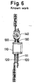
- a damper device is disclosed in Figs. 5, 6 and 7.
- the disclosed damper device of a clutch disk 101 is disposed between a clutch hub 110 and a side plate 120 and includes a coil spring 140 and a thrust member 130.
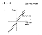
- the damper device performs a torque transmission via the coil spring 140 between the clutch hub 110 and the side plate 120. Torsional characteristics of the torque transmission have a hysteresis produced by the thrust member 130 ( as shown in Fig. 8).
- the thrust member 130 is includes a base material 131 and a friction member 132.
- the friction member 132 is adhered to a face of the base material 131 which facing to a flange portion of the clutch hub 110 by a adhesive layer 133.
- adhesive layer 133 is required for holding the friction member 132 to the base material 131, thereby causing an increase of number of parts or production process. The cost is also increased.
- a torsional damper apparatus includes a clutch hub having a hub portion and a flange portion extending in a radially outward direction from the hub portion, a first side plate and a second side plate coaxially disposed on opposite sides of the clutch hub and relatively rotatable with the clutch hub and first and second thrust members retained between contact faces of the clutch hub and the first side plate, and contact faces of the clutch hub and the second side plate respectively.
- At least one of the first thrust member and the second thrust member includes a base portion and a coating layer faces the flange portion and including a metallic particle having a smaller hardness than the clutch hub and a thermosetting resin.
- the number of parts or the production process may be reduced with the more stabilized hysteresis than the known torsional damper apparatus.
- Fig. 1 is a front view showing a structure of a clutch disk (a torsional damper apparatus) 1 according to the present embodiment.
- Fig. 2 is a cross-sectional view taken along a line A-A' of Fig. 1.
- Fig. 4 is an enlarged cross-sectional view in a vicinity of a thrust member of the clutch disk 1 taken along a line A-A' of Fig. 1.
- the clutch disk 1 includes a clutch hub 10, a side plate 20, a thrust member 30, a coil spring 40, and a cushion spring 50.
- the clutch hub 10 includes a hub portion and a flange 11 extending in a radially outward direction from the hub portion as shown in Figs. 1 and 2.
- the flange 11 is formed as a unit with the hub portion of the clutch hub 10.
- the flange 11 and the hub portion may be separately formed so that a small spring can be disposed therebetween. Then, a small torsional vibration can be absorbed between the flange 11 and the hub portion.
- the clutch hub 10 also includes a notch 12 that opens in the radially outward direction of the flange 11.
- the notch 12 is constituted in such a manner that each outer circumferential side of spring seats 41 and 42 (See Fig. 1) is positioned radially outward relative to an outer circumferential side of the flange 11.
- the side plate 20 is coaxially provided and relatively rotatable with the clutch hub 10. As shown in Fig. 2, the side plate 20 includes a first side plate 20A and a second side plate 20B disposed on opposite sides of the clutch hub 10 in an axial direction.
- the first side plate 20A and the second side plate 20B include window holes 21 for connecting the outer circumferential side of the coil spring 40.
- the first side plate 20A and the second side plate 20B are connected by a rivet pin 80 at the circumferential side thereof.
- the thrust member 30 is formed by washer-type resin and disposed between respective contact faces of the clutch hub 10 and the side plate 20. As shown in Figs. 2 and 3, the thrust member 30 includes a first thrust member 30A disposed between the respective contact faces of the clutch hub 10 and the first side plate 20A and a second thrust member 30B disposed between the respective contact faces of the clutch hub 10 and the second side plate 20B.
- the second thrust member 30B includes a base material portion 31 and a coating portion 32.
- the coating portion 32 is provided on the flange 11 side of the base material portion 31.
- the coating portion 32 is painted with a coating including soft metallic particle having smaller hardness than the clutch hub 10, and thermosetting resin.
- a thickness of the coating portion 32 is desirably between 15 ⁇ m and 35 ⁇ m.
- the soft metallic particle is desirably composed of a combination of one or more of tin, silver, zinc, lead, bismuth, cadmium, and indium.
- the zinc is most preferable.
- Particle in scaly shape having 10 ⁇ m in size and 0.1 ⁇ m in thickness, for example, may be used for the soft metallic particle.
- phenol resin, urea resin, melamine resin, epoxy resin, unsaturated polyester resin, alkyd resin, polyurethane resin, and ebonite may be used for the thermosetting resin.
- the phenol resin is most preferable.
- the coil spring 40 is disposed in the notch 12 and the window holes 21, facing to each other, formed on the clutch hub 10 and the side plates 20A and 20B respectively.
- Four coil springs 40 (or possibly two) are employed according to the present embodiment as shown in Fig. 1.
- Each coil spring 40 is received within the notch 12 and the window hole 21 while being supported by the pair of spring seats 41 and 42.
- a radially inward portion of the cushion spring 50 is connected to a radially outward portion of the second side plate 20B as shown in Fig. 2.
- the cushion spring 50 and the second side plate 20B are connected to each other via rivet pins 80.
- a pair of friction elements 60 each having an annular shape are fixed to opposite sides of the cushion spring 50 in the axial direction via rivets 70.
- the pair of friction elements 60 are retained between an engine flywheel and a pressure plate (not shown).
- the clutch hub 10 is provided with a spline portion at an inner peripheral surface where an input shaft of a transmission (not shown) having a spline portion is engaged.
- the clutch desk 1 according to the present embodiment is employed in the clutch disk in an aforementioned manner.
- a driving torque (torsional torque) of an engine (not shown) is transmitted to the cushion spring 50 of the clutch disk via the friction elements 60. Then, the driving torque is transmitted to the side plate 20B connected to the cushion spring 50. The fluctuation of the driving torque added to the clutch disk is transmitted to the clutch hub 10 while the hysteresis of the driving torque is buffered and stabilized between the side plates 20A and 20B and the clutch hub 10 by a compression of the coil spring 40. The driving torque is then transmitted to an input shaft of a transmission (not shown).
- Fig. 4 is a graph for comparing the hysteresis change along with the operating time of the thrust member 30 of the clutch desk 1.
- 1 the clutch desk 1 according to the present embodiment (See Fig. 3: the thrust member 30 whose face is painted with a coating including zinc particle and resin)
- 2 the clutch desk 1 according to a comparative example 1 (See Fig.
- the thrust member 30 whose face is adhered to the friction member), and 3 the clutch desk 1 according to a comparative example 2 (the thrust member 30 whose face is not painted with a coating including zinc particle and resin) were prepared for measuring the hysteresis change along with the operating time of the thrust member. Structures of these three clutch desk 1 other than the thrust member 30 are substantially same as each other.
- the comparative example 2 showed a large hysteresis change.
- the comparative example 1 showed a less hysteresis change than the comparative example 2.
- the present embodiment showed the least hysteresis change, i.e. the hysteresis change was further stabilized.
- the number of parts or the production process may be reduced with the more stabilized hysteresis than the known clutch desk.
Landscapes
- Engineering & Computer Science (AREA)
- General Engineering & Computer Science (AREA)
- Physics & Mathematics (AREA)
- Acoustics & Sound (AREA)
- Aviation & Aerospace Engineering (AREA)
- Mechanical Engineering (AREA)
- Mechanical Operated Clutches (AREA)
Applications Claiming Priority (2)
| Application Number | Priority Date | Filing Date | Title |
|---|---|---|---|
| JP2003070694 | 2003-03-14 | ||
| JP2003070694A JP2004278657A (ja) | 2003-03-14 | 2003-03-14 | 捩れ緩衝装置 |
Publications (2)
| Publication Number | Publication Date |
|---|---|
| EP1457708A2 true EP1457708A2 (fr) | 2004-09-15 |
| EP1457708A3 EP1457708A3 (fr) | 2005-01-05 |
Family
ID=32767996
Family Applications (1)
| Application Number | Title | Priority Date | Filing Date |
|---|---|---|---|
| EP04005524A Withdrawn EP1457708A3 (fr) | 2003-03-14 | 2004-03-09 | Un dispositif amortisseur torsionel |
Country Status (3)
| Country | Link |
|---|---|
| EP (1) | EP1457708A3 (fr) |
| JP (1) | JP2004278657A (fr) |
| CN (1) | CN1530563A (fr) |
Families Citing this family (2)
| Publication number | Priority date | Publication date | Assignee | Title |
|---|---|---|---|---|
| CN101440845B (zh) * | 2007-11-21 | 2013-05-08 | 柯明泉 | 一种摩托车发动机离合器毂 |
| JP5652084B2 (ja) * | 2010-09-24 | 2015-01-14 | アイシン精機株式会社 | トルク変動吸収装置 |
Family Cites Families (8)
| Publication number | Priority date | Publication date | Assignee | Title |
|---|---|---|---|---|
| JPS584828U (ja) * | 1981-07-01 | 1983-01-12 | トヨタ自動車株式会社 | クラツチデイスク |
| JPH0652088B2 (ja) * | 1985-09-30 | 1994-07-06 | アイシン精機株式会社 | クラツチデイスク |
| DE3918222A1 (de) * | 1988-06-04 | 1989-12-07 | Luk Lamellen & Kupplungsbau | Daempfungsvorkehrung |
| ES2122823B1 (es) * | 1993-11-26 | 2000-02-01 | Fichtel & Sachs Ag | Amortiguador de vibraciones de torsion en la cadena de accionamiento de un automovil, con anillo de friccion tensado axialmente. |
| JPH08312672A (ja) * | 1995-05-23 | 1996-11-26 | Exedy Corp | 摩擦部材及びそれを用いたダンパーディスク組立体 |
| EP0756104B1 (fr) * | 1995-07-24 | 2005-05-25 | Exedy Corporation | Assiètes de ressort améliorées dans un disque amortisseur |
| DE19828663A1 (de) * | 1997-06-27 | 1999-02-04 | Aisin Seiki | Reibbelagmaterial |
| JP2000179572A (ja) * | 1998-12-18 | 2000-06-27 | Exedy Corp | ダンパーディスク組立体 |
-
2003
- 2003-03-14 JP JP2003070694A patent/JP2004278657A/ja not_active Withdrawn
-
2004
- 2004-03-09 EP EP04005524A patent/EP1457708A3/fr not_active Withdrawn
- 2004-03-15 CN CNA2004100399605A patent/CN1530563A/zh active Pending
Also Published As
| Publication number | Publication date |
|---|---|
| JP2004278657A (ja) | 2004-10-07 |
| EP1457708A3 (fr) | 2005-01-05 |
| CN1530563A (zh) | 2004-09-22 |
Similar Documents
| Publication | Publication Date | Title |
|---|---|---|
| US7377853B2 (en) | Torque fluctuation absorbing device | |
| US6209701B1 (en) | Damper disk assembly | |
| CN108223689B (zh) | 扭矩变动吸收装置 | |
| GB2127131A (en) | Damper disc | |
| US5169357A (en) | Torsion damping device, in particular for a clutch friction disc for a motor vehicle | |
| US6645079B2 (en) | Damper mechanism | |
| US4068749A (en) | Clutch plate and damper assembly | |
| US6676525B2 (en) | Damper mechanism | |
| US4789374A (en) | Torsional vibration absorber | |
| EP0790433B1 (fr) | Elément de plaque pour un ensemble de disque amortisseur comportant des pièces de support s'étendant radialement | |
| EP1348886A1 (fr) | Disque amortisseur de torsion | |
| EP1457708A2 (fr) | Un dispositif amortisseur torsionel | |
| JP3731236B2 (ja) | トーションダンパ | |
| JPH09112570A (ja) | ダンパーディスク組立体、クラッチディスク組立体の摩擦連結部及びクラッチディスク組立体 | |
| CN111734783B (zh) | 集成多级可变阻尼的飞轮减振器 | |
| US7568569B2 (en) | Friction clutch, particularly for a motor vehicle, comprising differentiated friction means | |
| US4651860A (en) | Clutch disk supported by a resin bushing | |
| JP3434389B2 (ja) | 摩擦発生機構 | |
| US20040206201A1 (en) | Flywheel assembly | |
| JPH10103407A (ja) | ダンパー機構 | |
| JP3619372B2 (ja) | ダンパーディスク組立体 | |
| GB2138105A (en) | Damper disc | |
| JP2000320614A (ja) | 動力伝達装置 | |
| US20070099710A1 (en) | Flexible flywheel | |
| JPH0137226Y2 (fr) |
Legal Events
| Date | Code | Title | Description |
|---|---|---|---|
| PUAI | Public reference made under article 153(3) epc to a published international application that has entered the european phase |
Free format text: ORIGINAL CODE: 0009012 |
|
| AK | Designated contracting states |
Kind code of ref document: A2 Designated state(s): AT BE BG CH CY CZ DE DK EE ES FI FR GB GR HU IE IT LI LU MC NL PL PT RO SE SI SK TR |
|
| AX | Request for extension of the european patent |
Extension state: AL LT LV MK |
|
| PUAL | Search report despatched |
Free format text: ORIGINAL CODE: 0009013 |
|
| AK | Designated contracting states |
Kind code of ref document: A3 Designated state(s): AT BE BG CH CY CZ DE DK EE ES FI FR GB GR HU IE IT LI LU MC NL PL PT RO SE SI SK TR |
|
| AX | Request for extension of the european patent |
Extension state: AL LT LV MK |
|
| AKX | Designation fees paid | ||
| REG | Reference to a national code |
Ref country code: DE Ref legal event code: 8566 |
|
| STAA | Information on the status of an ep patent application or granted ep patent |
Free format text: STATUS: THE APPLICATION IS DEEMED TO BE WITHDRAWN |
|
| 18D | Application deemed to be withdrawn |
Effective date: 20050706 |