EP1460312A2 - Dispositif d'entraînement d'un organe de sortie - Google Patents
Dispositif d'entraînement d'un organe de sortie Download PDFInfo
- Publication number
- EP1460312A2 EP1460312A2 EP04014047A EP04014047A EP1460312A2 EP 1460312 A2 EP1460312 A2 EP 1460312A2 EP 04014047 A EP04014047 A EP 04014047A EP 04014047 A EP04014047 A EP 04014047A EP 1460312 A2 EP1460312 A2 EP 1460312A2
- Authority
- EP
- European Patent Office
- Prior art keywords
- output member
- input shaft
- movement
- gripping
- alternating
- Prior art date
- Legal status (The legal status is an assumption and is not a legal conclusion. Google has not performed a legal analysis and makes no representation as to the accuracy of the status listed.)
- Granted
Links
- 238000013519 translation Methods 0.000 claims description 4
- 238000004519 manufacturing process Methods 0.000 description 3
- 230000014616 translation Effects 0.000 description 3
- 230000005540 biological transmission Effects 0.000 description 2
- 238000006073 displacement reaction Methods 0.000 description 2
- 230000001960 triggered effect Effects 0.000 description 2
- 240000001592 Amaranthus caudatus Species 0.000 description 1
- 235000009328 Amaranthus caudatus Nutrition 0.000 description 1
- 210000000078 claw Anatomy 0.000 description 1
- 238000005553 drilling Methods 0.000 description 1
- 210000003746 feather Anatomy 0.000 description 1
Images

Classifications
-
- F—MECHANICAL ENGINEERING; LIGHTING; HEATING; WEAPONS; BLASTING
- F16—ENGINEERING ELEMENTS AND UNITS; GENERAL MEASURES FOR PRODUCING AND MAINTAINING EFFECTIVE FUNCTIONING OF MACHINES OR INSTALLATIONS; THERMAL INSULATION IN GENERAL
- F16H—GEARING
- F16H31/00—Other gearings with freewheeling members or other intermittently driving members
- F16H31/007—Step-by-step mechanisms for linear motion
- F16H31/008—Step-by-step mechanisms for linear motion with friction means
-
- F—MECHANICAL ENGINEERING; LIGHTING; HEATING; WEAPONS; BLASTING
- F16—ENGINEERING ELEMENTS AND UNITS; GENERAL MEASURES FOR PRODUCING AND MAINTAINING EFFECTIVE FUNCTIONING OF MACHINES OR INSTALLATIONS; THERMAL INSULATION IN GENERAL
- F16H—GEARING
- F16H29/00—Gearings for conveying rotary motion with intermittently-driving members, e.g. with freewheel action
- F16H29/02—Gearings for conveying rotary motion with intermittently-driving members, e.g. with freewheel action between one of the shafts and an oscillating or reciprocating intermediate member, not rotating with either of the shafts
- F16H29/08—Gearings for conveying rotary motion with intermittently-driving members, e.g. with freewheel action between one of the shafts and an oscillating or reciprocating intermediate member, not rotating with either of the shafts in which the transmission ratio is changed by adjustment of the path of movement, the location of the pivot, or the effective length, of an oscillating connecting member
-
- F—MECHANICAL ENGINEERING; LIGHTING; HEATING; WEAPONS; BLASTING
- F16—ENGINEERING ELEMENTS AND UNITS; GENERAL MEASURES FOR PRODUCING AND MAINTAINING EFFECTIVE FUNCTIONING OF MACHINES OR INSTALLATIONS; THERMAL INSULATION IN GENERAL
- F16H—GEARING
- F16H29/00—Gearings for conveying rotary motion with intermittently-driving members, e.g. with freewheel action
- F16H29/02—Gearings for conveying rotary motion with intermittently-driving members, e.g. with freewheel action between one of the shafts and an oscillating or reciprocating intermediate member, not rotating with either of the shafts
-
- Y—GENERAL TAGGING OF NEW TECHNOLOGICAL DEVELOPMENTS; GENERAL TAGGING OF CROSS-SECTIONAL TECHNOLOGIES SPANNING OVER SEVERAL SECTIONS OF THE IPC; TECHNICAL SUBJECTS COVERED BY FORMER USPC CROSS-REFERENCE ART COLLECTIONS [XRACs] AND DIGESTS
- Y10—TECHNICAL SUBJECTS COVERED BY FORMER USPC
- Y10T—TECHNICAL SUBJECTS COVERED BY FORMER US CLASSIFICATION
- Y10T74/00—Machine element or mechanism
- Y10T74/15—Intermittent grip type mechanical movement
- Y10T74/1503—Rotary to intermittent unidirectional motion
- Y10T74/1508—Rotary crank or eccentric drive
-
- Y—GENERAL TAGGING OF NEW TECHNOLOGICAL DEVELOPMENTS; GENERAL TAGGING OF CROSS-SECTIONAL TECHNOLOGIES SPANNING OVER SEVERAL SECTIONS OF THE IPC; TECHNICAL SUBJECTS COVERED BY FORMER USPC CROSS-REFERENCE ART COLLECTIONS [XRACs] AND DIGESTS
- Y10—TECHNICAL SUBJECTS COVERED BY FORMER USPC
- Y10T—TECHNICAL SUBJECTS COVERED BY FORMER US CLASSIFICATION
- Y10T74/00—Machine element or mechanism
- Y10T74/15—Intermittent grip type mechanical movement
- Y10T74/1558—Grip units and features
- Y10T74/1587—Grip features
- Y10T74/1598—Driven ratchet-bar and power dog
Definitions
- the invention relates to a device for driving an output member with a rotating input shaft.
- Devices for driving an output member with a rotating input shaft are known from the prior art and are used in drilling machines, impact drills or the like. Such devices have between the input shaft and the output member a plurality of gears provided as a translation and a positive connection between the input shaft and the output member, in order to drive a high speed of the input shaft serving as a drive in a lower movement frequency or speed of the output member while increasing the transform the output member to be transmitted driving force.
- a device for driving an output member with a rotationally drivable input shaft wherein means for transmitting a drive torque of the input shaft to the output member are arranged between the input shaft and the output member.
- a non-positive connection can be established between a first means and the output member, by means of which an alternating movement of the first means can be converted into a movement of the output member.
- the positive connection is controlled by a tensioning force of a spring element.
- a second means is connected to the first means via a driver so that it can rotate about a pivot point.
- the second means is rotatably mounted on an axis and provided with an arm directed radially outward from the axis.
- the first means and the second means are rotatably connected to one another in such a way that an alternating movement of the first means causes a rotational movement of the arm about the axis and jamming of a transmission element.
- the transmission element is arranged between an inner surface of a ring element which is arranged coaxially to the axis and surrounds the second means and the end of the arm which faces the ring element.
- the invention is based on a device for driving an output member with a rotationally drivable input shaft, wherein means for transmitting a drive torque of the input shaft to the output member are arranged between the input shaft and the output member, wherein a non-positive operative connection can be established between a first means and the output member , by means of which an alternating movement of the first means can be converted into a movement of the output member, the means being designed such that the alternating rotational movement of the first means can be converted into a translational movement of the output member.
- At least one lever element is rotatably attached to the first means, via which the first means is operatively connected to at least one gripping element.
- the device according to the invention has the advantage that a high speed of the input shaft can be converted into a considerably slower movement or movement frequency of the output element and a desired large driving force of the output element can be generated.
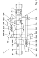
- FIG. 1 and 2 show a device 10 for driving an output member 46 with a rotationally drivable input shaft 14 of the device 10, which is at the same time the output shaft of an electric motor (not shown in more detail).
- Means 16, 58 for transmitting a drive torque of the input shaft 14 to the output member 46 are arranged between the input shaft 14 and the output member 46.
- FIG. 10 An embodiment of the device 10 is shown, in which an alternating pivoting movement of a first means 16, which is triggered by a rotation of the input shaft 14, is converted into a translational movement of the output member 46, which is designed as a tool holder of a foxtail saw or the like.
- the first means 16 is T-shaped, with a first crossbeam running essentially perpendicular to the output member 46 and a leg running essentially parallel to the output member 46.
- the first means 16 is pivotally mounted in a bearing 84.
- the leg is fork-shaped at its end and encompasses an eccentric 70 driven by the input shaft 14.
- two lever elements 54A, 54B can be rotated via bolts 55A, 55B serving as pivot points attached.
- the two lever elements 54A, 54B run essentially parallel to the output member 46 and establish an operative connection between the rocker of the means 16 and two gripping elements 58A, 58B via two bearing bolts 118A, 118B.
- the two gripping elements 58A, 58B are connected to one another via a further lever element 62 which extends essentially transversely to the output member 46 and can be tilted as a function of the alternating movement of the rocker means 16 relative to a center line 64 of the output member 46.
- the further lever element 62 is connected in an articulated manner to the gripping elements 58A, 58B via two pins 66A, 66B. Operational the two pins 66A, 66B are translationally displaced approximately parallel to the central axis 64 of the output member 46. In order to ensure such a movement of the pins 66A, 66B, bores for receiving the pins 66A, 66B of the further lever element 62 are formed with a larger diameter than the diameter of the pins 66A, 66B.
- the rocker of the means 16 can be driven alternately in its movement by the input shaft 14 via the eccentric 70, namely pivotable clockwise and counterclockwise about its bearing point 84.
- the two gripping elements 58A, 58B each overlap the output member 46 with a hub-shaped gripping arm 72A, 72B in order to transmit the alternating movement of the rocker of the means 16.
- the gripping arms 72A, 72B have on their inner sides 76A, 76B facing the output member 46 a bulges directed in the direction of the output member 46, which are in contact with the output member 46.
- the gripping arms 72A, 72B and the output member 46 are arranged relative to one another such that when the rocker 16 of the means 16 pivots counterclockwise, the gripping element 58A is jammed with the output member 46 and a stepwise translational movement of the output member 46 in the direction facing away from the input shaft 14 causes and the second gripping element 58B simultaneously releases the output element 46.
- the gripping element 58B jams with the output member 46 and causes a step-by-step translational movement of the output member 46 in the direction facing away from the input shaft 14, the first gripping element 58A simultaneously releasing the output member 46.
- a spring element 82A, 82B is arranged, which has two stable end positions of the gripping elements 58A, 58B ensures.
- a bolt 88 is connected to the output member 46.
- the bolt 88 engages in an opening 90 of a triangular plate element 96 which is tiltably arranged between a snap element 92 and a third lever element 94 which extends essentially transversely to the output member 46.
- the snap element 92 is rotatably mounted via a further bolt 98 in a housing of the device 10 (not shown in more detail) and is rotatably connected to the plate element 96 via a bolt 100.
- the snap element 92 has at its end facing away from the plate element 96 a wave-shaped recess 102, in which a with the further lever element 62 fixed pin 104 is arranged.
- a spring 106 which is connected at one end to the housing of the device 10 and at the other end to the snap element 92, causes the snap element 92 to always rest with its recess 102 on the pin 104.
- the opening 90 of the plate element 96 or its shape is provided in such a way that it has a plurality of guide slots 112, 114 and 116 with different lengths.
- the end of the third lever element 94 is rotatably connected to a turntable 68 via a bolt 74 by its end facing away from the connection point with the plate element 96.
- a rotation of the turntable 68 by an operator has the result that the plate element 96 is tilted in such a way that a desired guide slot 110, 112, 114 or 116 is set for the pin 88 as a guide for the movement of the pin 88, as a result of which the turntable 68 represents a means for setting a total stroke of the output member 46 resulting from the individual strokes or a limitation of the adjustment path.
Landscapes
- Engineering & Computer Science (AREA)
- General Engineering & Computer Science (AREA)
- Mechanical Engineering (AREA)
- Transmission Devices (AREA)
Applications Claiming Priority (3)
| Application Number | Priority Date | Filing Date | Title |
|---|---|---|---|
| DE10064899 | 2000-12-23 | ||
| DE10064899A DE10064899A1 (de) | 2000-12-23 | 2000-12-23 | Vorrichtung zum Antreiben eines Ausgangsglieds |
| EP01990320A EP1348084B1 (fr) | 2000-12-23 | 2001-12-19 | Dispositif d'entrainement d'un organe de sortie |
Related Parent Applications (2)
| Application Number | Title | Priority Date | Filing Date |
|---|---|---|---|
| EP01990320.2 Division | 2001-12-19 | ||
| EP01990320A Division EP1348084B1 (fr) | 2000-12-23 | 2001-12-19 | Dispositif d'entrainement d'un organe de sortie |
Publications (3)
| Publication Number | Publication Date |
|---|---|
| EP1460312A2 true EP1460312A2 (fr) | 2004-09-22 |
| EP1460312A3 EP1460312A3 (fr) | 2005-05-25 |
| EP1460312B1 EP1460312B1 (fr) | 2006-09-13 |
Family
ID=7668892
Family Applications (3)
| Application Number | Title | Priority Date | Filing Date |
|---|---|---|---|
| EP01990320A Expired - Lifetime EP1348084B1 (fr) | 2000-12-23 | 2001-12-19 | Dispositif d'entrainement d'un organe de sortie |
| EP04014047A Expired - Lifetime EP1460312B1 (fr) | 2000-12-23 | 2001-12-19 | Dispositif d'entraînement d'un organe de sortie |
| EP04014046A Expired - Lifetime EP1457709B1 (fr) | 2000-12-23 | 2001-12-19 | Dispositif d'entraînement d'un organe de sortie |
Family Applications Before (1)
| Application Number | Title | Priority Date | Filing Date |
|---|---|---|---|
| EP01990320A Expired - Lifetime EP1348084B1 (fr) | 2000-12-23 | 2001-12-19 | Dispositif d'entrainement d'un organe de sortie |
Family Applications After (1)
| Application Number | Title | Priority Date | Filing Date |
|---|---|---|---|
| EP04014046A Expired - Lifetime EP1457709B1 (fr) | 2000-12-23 | 2001-12-19 | Dispositif d'entraînement d'un organe de sortie |
Country Status (6)
| Country | Link |
|---|---|
| US (2) | US7040185B2 (fr) |
| EP (3) | EP1348084B1 (fr) |
| JP (1) | JP2004516437A (fr) |
| CN (2) | CN1287104C (fr) |
| DE (4) | DE10064899A1 (fr) |
| WO (1) | WO2002052173A1 (fr) |
Families Citing this family (4)
| Publication number | Priority date | Publication date | Assignee | Title |
|---|---|---|---|---|
| US10240666B2 (en) * | 2013-03-12 | 2019-03-26 | Motus Labs, LLC | Simplified gearbox mechanism |
| US10151375B2 (en) * | 2013-03-12 | 2018-12-11 | Motus Labs, LLC | Motorized gearbox mechanism |
| CN106346052B (zh) * | 2016-11-04 | 2018-02-09 | 泰州市光明电子材料有限公司 | 一种钻头直径可变的打孔机构 |
| CN109058408B (zh) * | 2018-08-16 | 2021-05-11 | 西安工业大学 | 一种可伸缩式多功能机械间歇传动装置 |
Citations (1)
| Publication number | Priority date | Publication date | Assignee | Title |
|---|---|---|---|---|
| GB191024157A (en) | 1909-12-10 | 1911-03-23 | Bosch Robert | Apparatus for Varying the Speed of Rotation of a Driven Shaft Independently of the Reciprocating Stroke of the Driving Member. |
Family Cites Families (36)
| Publication number | Priority date | Publication date | Assignee | Title |
|---|---|---|---|---|
| US296804A (en) * | 1884-04-15 | Rock-drill and well-boring machine | ||
| US495077A (en) * | 1893-04-11 | Electric-arc lamp | ||
| DE259132C (fr) | ||||
| US131640A (en) * | 1872-09-24 | Improvement in griping-blocks for presses | ||
| US1203408A (en) * | 1912-12-13 | 1916-10-31 | Remy Brothers Company | Clutch drive mechanism. |
| US1168091A (en) * | 1915-09-20 | 1916-01-11 | John W Maughmer | Mechanical movement. |
| DE677130C (de) * | 1932-12-08 | 1939-06-19 | Faber & Schleicher Akt Ges | Vorgreifersteuerung fuer Bogendruckmaschinen |
| US1985406A (en) * | 1934-01-04 | 1934-12-25 | Nathan B Galkin | Intermittent driving mechanism |
| DE757391C (de) * | 1937-12-14 | 1953-10-05 | Siemens Schuckertwerke A G | Wagenvorzieheinrichtung, insbesondere fuer Foerderwagen im Bergwerkbetrieb |
| DE844522C (de) * | 1950-09-14 | 1952-07-21 | Heinrich Gensheimer & Soehne M | Schaltwechselgetriebe fuer stufenlose Drehzahlregelung |
| US2692510A (en) * | 1951-08-15 | 1954-10-26 | Honeywell Regulator Co | Control apparatus |
| DE1049188B (de) | 1954-06-19 | 1959-01-22 | Hell Rudolf Dr Ing Fa | Getriebe zur Umwandlung einer hin- und hergehenden Bewegung in eine periodisch fortschreitende Bewegung |
| US2997888A (en) * | 1958-04-16 | 1961-08-29 | Hunter James Machine Co | Adjustable intermittent feed mechanism |
| GB1005947A (en) * | 1963-07-24 | 1965-09-29 | Metal Box Co Ltd | Improvements in or relating to apparatus for closing containers |
| US3332301A (en) * | 1964-11-24 | 1967-07-25 | Origineers Inc | Gear drive |
| US3298666A (en) * | 1965-09-24 | 1967-01-17 | Flexible Sewertool Corp | Reciprocable clutch means for feeding sewer tool drive rod |
| US3589202A (en) * | 1969-03-19 | 1971-06-29 | Richard B Stanley | Linear actuator |
| US3726149A (en) * | 1970-08-17 | 1973-04-10 | L Ilines | Pressure relief apparatus for potato dough extruder |
| DE2114147A1 (de) * | 1971-03-24 | 1972-10-05 | Voth Guenter H | Getriebe |
| US3848474A (en) * | 1973-01-10 | 1974-11-19 | A Epstein | Variable-speed, positive-drive transmission providing output speeds from zero r.p.m. up to full output r.p.m. |
| US3930416A (en) * | 1974-09-16 | 1976-01-06 | Dahltron Corporation | Laminated drive arms for speed reducer |
| US3951005A (en) * | 1974-09-16 | 1976-04-20 | Dahltron Corporation | Multiple arm speed reducer |
| US3979967A (en) * | 1975-07-30 | 1976-09-14 | California Traders | Shift control device |
| GB2054794B (en) * | 1979-07-31 | 1983-03-02 | Turner H R | Adjustment mechanism |
| US4378706A (en) * | 1979-09-17 | 1983-04-05 | Canon Kabushiki Kaisha | Reciprocally driving device |
| DE3131903A1 (de) | 1981-08-12 | 1983-02-24 | Siemens AG, 1000 Berlin und 8000 München | Elektromotorische antriebsvorrichtung fuer die betaetigung eines drehschalters in elektrischen schaltanlagen |
| US4565105A (en) * | 1983-09-23 | 1986-01-21 | Peterson Walter O | Power transmission apparatus |
| US4680980A (en) * | 1985-10-03 | 1987-07-21 | A. O. Smith Harvestore Products, Inc. | Drive mechanism |
| EP0368526B1 (fr) * | 1988-10-28 | 1994-01-05 | Unisia Jecs Corporation | Embrayage |
| DE69102392T2 (de) * | 1990-10-23 | 1995-02-16 | Teijin Seiki Co Ltd | Mechanismus zum Umwandeln einer Rotationsbewegung in eine Längsbewegung. |
| JPH0754954A (ja) * | 1993-07-22 | 1995-02-28 | Hakko Denki Seisakusho:Kk | サーボモーターを用いた駆動系 |
| DE29606762U1 (de) * | 1996-04-13 | 1996-07-18 | Festo Kg, 73734 Esslingen | Schrittantrieb |
| CN1203969A (zh) | 1997-06-26 | 1999-01-06 | 重机株式会社 | 缝纫机的摆动机构 |
| DE19743483C2 (de) * | 1997-10-01 | 2001-01-04 | Matthias Berger | Getriebe mit stufenlos einstellbarer Übersetzung |
| GR980100044A (el) * | 1998-01-30 | 1999-09-30 | Συστημα μεταδοσης | |
| AU2899900A (en) | 1999-03-02 | 2000-09-21 | Nps Allelix Corp. | Cloned human sphingosine kinase homologues |
-
2000
- 2000-12-23 DE DE10064899A patent/DE10064899A1/de not_active Ceased
-
2001
- 2001-12-19 CN CNB018206816A patent/CN1287104C/zh not_active Expired - Fee Related
- 2001-12-19 WO PCT/DE2001/004792 patent/WO2002052173A1/fr not_active Ceased
- 2001-12-19 JP JP2002553034A patent/JP2004516437A/ja active Pending
- 2001-12-19 EP EP01990320A patent/EP1348084B1/fr not_active Expired - Lifetime
- 2001-12-19 EP EP04014047A patent/EP1460312B1/fr not_active Expired - Lifetime
- 2001-12-19 CN CNA200510125386XA patent/CN1811229A/zh active Pending
- 2001-12-19 EP EP04014046A patent/EP1457709B1/fr not_active Expired - Lifetime
- 2001-12-19 DE DE50107076T patent/DE50107076D1/de not_active Expired - Fee Related
- 2001-12-19 US US10/451,355 patent/US7040185B2/en not_active Expired - Fee Related
- 2001-12-19 DE DE50111027T patent/DE50111027D1/de not_active Expired - Fee Related
- 2001-12-19 DE DE50111026T patent/DE50111026D1/de not_active Expired - Fee Related
-
2005
- 2005-12-13 US US11/301,366 patent/US20060090580A1/en not_active Abandoned
Patent Citations (1)
| Publication number | Priority date | Publication date | Assignee | Title |
|---|---|---|---|---|
| GB191024157A (en) | 1909-12-10 | 1911-03-23 | Bosch Robert | Apparatus for Varying the Speed of Rotation of a Driven Shaft Independently of the Reciprocating Stroke of the Driving Member. |
Also Published As
| Publication number | Publication date |
|---|---|
| WO2002052173A1 (fr) | 2002-07-04 |
| JP2004516437A (ja) | 2004-06-03 |
| DE10064899A1 (de) | 2002-07-25 |
| EP1457709A3 (fr) | 2005-05-25 |
| DE50111026D1 (de) | 2006-10-26 |
| CN1811229A (zh) | 2006-08-02 |
| CN1287104C (zh) | 2006-11-29 |
| EP1457709A2 (fr) | 2004-09-15 |
| EP1460312B1 (fr) | 2006-09-13 |
| US7040185B2 (en) | 2006-05-09 |
| US20040087404A1 (en) | 2004-05-06 |
| EP1348084B1 (fr) | 2005-08-10 |
| EP1348084A1 (fr) | 2003-10-01 |
| EP1460312A3 (fr) | 2005-05-25 |
| EP1457709B1 (fr) | 2006-09-13 |
| DE50111027D1 (de) | 2006-10-26 |
| DE50107076D1 (de) | 2005-09-15 |
| CN1481485A (zh) | 2004-03-10 |
| US20060090580A1 (en) | 2006-05-04 |
Similar Documents
| Publication | Publication Date | Title |
|---|---|---|
| DE69806462T2 (de) | Drehschlagwerkzeug mit evolventem profilhammer | |
| EP1932625B1 (fr) | Appareil d'outillage manuel électrique | |
| DE68918335T2 (de) | Antrieb für ein Bohr- und/oder Schlagwerkzeug. | |
| DE2323268C3 (de) | Schlagbohrmaschine | |
| EP3638457B1 (fr) | Machine-outil portative | |
| DE202008001449U1 (de) | Schalteinrichtung für Schlagwerkzeug | |
| EP0200844A1 (fr) | Marteau perforateur | |
| EP2342050B1 (fr) | Machine-outil manuelle équipée d'une transmission débrayable | |
| DE2543786C3 (de) | Drehschlagkupplung, insbesondere an einem Schlagschrauber | |
| DE3618024A1 (de) | Elektrowerkzeug mit schaltkupplung | |
| EP2277646A2 (fr) | Dispositif de serrage de pièces usinées pour l'extension de levage pour le mandrin existant d'une machine | |
| DE102007062248A1 (de) | Handwerkzeugmaschine mit einer, mindestens eine drehbar gelagerte Zwischenwelle umfassenden Getriebevorrichtung | |
| WO2008006634A1 (fr) | Outil électroportatif muni d'un groupe de percussion | |
| EP1460312A2 (fr) | Dispositif d'entraînement d'un organe de sortie | |
| DE3932413A1 (de) | Bohrhammer | |
| DE3136264C2 (de) | Elektropneumatischer Drehschlagbohrhammer | |
| DE102010007917B4 (de) | Handbetätigtes Werkzeug | |
| DE2039702C2 (de) | Schlagvorrichtung für Drehwerkzeuge, insbesondere Schlagschrauber | |
| DE102006061600A1 (de) | Elektrohandwerkzeuggerät | |
| DE10050376C2 (de) | Bohrhammer | |
| DE9307523U1 (de) | Elektrowerkzeug, insbesondere Schlagbohrmaschine oder Bohrhammer | |
| DE19943904A1 (de) | Getriebeanordnung für ein Arbeitsgerät | |
| DE102004019778B4 (de) | Schaltstück | |
| DE102009028633A1 (de) | Vorrichtung für eine Handwerkzeugmaschine und Handwerkzeugmaschine | |
| DE2510020C3 (de) | Schlagend arbeitende Vorrichtung zum Herstellen von Bohrlöchern im Boden |
Legal Events
| Date | Code | Title | Description |
|---|---|---|---|
| PUAI | Public reference made under article 153(3) epc to a published international application that has entered the european phase |
Free format text: ORIGINAL CODE: 0009012 |
|
| AC | Divisional application: reference to earlier application |
Ref document number: 1348084 Country of ref document: EP Kind code of ref document: P |
|
| AK | Designated contracting states |
Kind code of ref document: A2 Designated state(s): CH DE GB LI |
|
| PUAL | Search report despatched |
Free format text: ORIGINAL CODE: 0009013 |
|
| AK | Designated contracting states |
Kind code of ref document: A3 Designated state(s): CH DE GB LI |
|
| RIC1 | Information provided on ipc code assigned before grant |
Ipc: 7F 16H 29/08 A Ipc: 7F 16H 31/00 B |
|
| 17P | Request for examination filed |
Effective date: 20051125 |
|
| AKX | Designation fees paid |
Designated state(s): CH DE GB LI |
|
| GRAP | Despatch of communication of intention to grant a patent |
Free format text: ORIGINAL CODE: EPIDOSNIGR1 |
|
| GRAS | Grant fee paid |
Free format text: ORIGINAL CODE: EPIDOSNIGR3 |
|
| GRAA | (expected) grant |
Free format text: ORIGINAL CODE: 0009210 |
|
| AC | Divisional application: reference to earlier application |
Ref document number: 1348084 Country of ref document: EP Kind code of ref document: P |
|
| AK | Designated contracting states |
Kind code of ref document: B1 Designated state(s): CH DE GB LI |
|
| REG | Reference to a national code |
Ref country code: GB Ref legal event code: FG4D Free format text: NOT ENGLISH |
|
| REG | Reference to a national code |
Ref country code: CH Ref legal event code: EP |
|
| REG | Reference to a national code |
Ref country code: CH Ref legal event code: NV Representative=s name: SCINTILLA AG, DIREKTION |
|
| REF | Corresponds to: |
Ref document number: 50111027 Country of ref document: DE Date of ref document: 20061026 Kind code of ref document: P |
|
| PG25 | Lapsed in a contracting state [announced via postgrant information from national office to epo] |
Ref country code: LI Free format text: LAPSE BECAUSE OF NON-PAYMENT OF DUE FEES Effective date: 20061231 Ref country code: CH Free format text: LAPSE BECAUSE OF NON-PAYMENT OF DUE FEES Effective date: 20061231 |
|
| GBT | Gb: translation of ep patent filed (gb section 77(6)(a)/1977) |
Effective date: 20061207 |
|
| PG25 | Lapsed in a contracting state [announced via postgrant information from national office to epo] |
Ref country code: DE Free format text: LAPSE BECAUSE OF NON-PAYMENT OF DUE FEES Effective date: 20070703 |
|
| PLBE | No opposition filed within time limit |
Free format text: ORIGINAL CODE: 0009261 |
|
| STAA | Information on the status of an ep patent application or granted ep patent |
Free format text: STATUS: NO OPPOSITION FILED WITHIN TIME LIMIT |
|
| REG | Reference to a national code |
Ref country code: CH Ref legal event code: PL |
|
| 26N | No opposition filed |
Effective date: 20070614 |
|
| GBPC | Gb: european patent ceased through non-payment of renewal fee |
Effective date: 20061219 |
|
| PG25 | Lapsed in a contracting state [announced via postgrant information from national office to epo] |
Ref country code: GB Free format text: LAPSE BECAUSE OF NON-PAYMENT OF DUE FEES Effective date: 20061219 |