EP1465171A2 - Optische Abtastvorrichtung und Objektivlinse dafür - Google Patents
Optische Abtastvorrichtung und Objektivlinse dafür Download PDFInfo
- Publication number
- EP1465171A2 EP1465171A2 EP04101197A EP04101197A EP1465171A2 EP 1465171 A2 EP1465171 A2 EP 1465171A2 EP 04101197 A EP04101197 A EP 04101197A EP 04101197 A EP04101197 A EP 04101197A EP 1465171 A2 EP1465171 A2 EP 1465171A2
- Authority
- EP
- European Patent Office
- Prior art keywords
- optical
- optical element
- pickup apparatus
- light flux
- objective
- Prior art date
- Legal status (The legal status is an assumption and is not a legal conclusion. Google has not performed a legal analysis and makes no representation as to the accuracy of the status listed.)
- Ceased
Links
- 230000003287 optical effect Effects 0.000 title claims abstract description 371
- 230000004907 flux Effects 0.000 claims abstract description 114
- 230000004075 alteration Effects 0.000 claims abstract description 41
- 239000011241 protective layer Substances 0.000 claims description 22
- 239000000463 material Substances 0.000 claims description 14
- 230000008859 change Effects 0.000 claims description 7
- 239000011521 glass Substances 0.000 claims description 6
- 230000006866 deterioration Effects 0.000 claims description 4
- 238000006073 displacement reaction Methods 0.000 claims description 4
- 239000000758 substrate Substances 0.000 claims 3
- 239000004065 semiconductor Substances 0.000 description 33
- 238000001514 detection method Methods 0.000 description 21
- 230000007246 mechanism Effects 0.000 description 12
- 201000009310 astigmatism Diseases 0.000 description 7
- XEEYBQQBJWHFJM-UHFFFAOYSA-N Iron Chemical compound [Fe] XEEYBQQBJWHFJM-UHFFFAOYSA-N 0.000 description 4
- 230000007613 environmental effect Effects 0.000 description 3
- 230000002093 peripheral effect Effects 0.000 description 3
- 238000010586 diagram Methods 0.000 description 2
- 229910052742 iron Inorganic materials 0.000 description 2
- 230000005540 biological transmission Effects 0.000 description 1
- 230000015572 biosynthetic process Effects 0.000 description 1
- 239000010410 layer Substances 0.000 description 1
- 238000012827 research and development Methods 0.000 description 1
- 239000007787 solid Substances 0.000 description 1
Images


Classifications
-
- E—FIXED CONSTRUCTIONS
- E03—WATER SUPPLY; SEWERAGE
- E03C—DOMESTIC PLUMBING INSTALLATIONS FOR FRESH WATER OR WASTE WATER; SINKS
- E03C1/00—Domestic plumbing installations for fresh water or waste water; Sinks
- E03C1/12—Plumbing installations for waste water; Basins or fountains connected thereto; Sinks
- E03C1/30—Devices to facilitate removing of obstructions in waste-pipes or sinks
- E03C1/302—Devices to facilitate removing of obstructions in waste-pipes or sinks using devices moved through the pipes
-
- G—PHYSICS
- G11—INFORMATION STORAGE
- G11B—INFORMATION STORAGE BASED ON RELATIVE MOVEMENT BETWEEN RECORD CARRIER AND TRANSDUCER
- G11B7/00—Recording or reproducing by optical means, e.g. recording using a thermal beam of optical radiation by modifying optical properties or the physical structure, reproducing using an optical beam at lower power by sensing optical properties; Record carriers therefor
- G11B7/12—Heads, e.g. forming of the optical beam spot or modulation of the optical beam
- G11B7/135—Means for guiding the beam from the source to the record carrier or from the record carrier to the detector
- G11B7/1372—Lenses
- G11B7/1378—Separate aberration correction lenses; Cylindrical lenses to generate astigmatism; Beam expanders
-
- G—PHYSICS
- G11—INFORMATION STORAGE
- G11B—INFORMATION STORAGE BASED ON RELATIVE MOVEMENT BETWEEN RECORD CARRIER AND TRANSDUCER
- G11B7/00—Recording or reproducing by optical means, e.g. recording using a thermal beam of optical radiation by modifying optical properties or the physical structure, reproducing using an optical beam at lower power by sensing optical properties; Record carriers therefor
- G11B7/12—Heads, e.g. forming of the optical beam spot or modulation of the optical beam
- G11B7/125—Optical beam sources therefor, e.g. laser control circuitry specially adapted for optical storage devices; Modulators, e.g. means for controlling the size or intensity of optical spots or optical traces
- G11B7/127—Lasers; Multiple laser arrays
- G11B7/1275—Two or more lasers having different wavelengths
-
- G—PHYSICS
- G11—INFORMATION STORAGE
- G11B—INFORMATION STORAGE BASED ON RELATIVE MOVEMENT BETWEEN RECORD CARRIER AND TRANSDUCER
- G11B7/00—Recording or reproducing by optical means, e.g. recording using a thermal beam of optical radiation by modifying optical properties or the physical structure, reproducing using an optical beam at lower power by sensing optical properties; Record carriers therefor
- G11B7/12—Heads, e.g. forming of the optical beam spot or modulation of the optical beam
- G11B7/135—Means for guiding the beam from the source to the record carrier or from the record carrier to the detector
- G11B7/1353—Diffractive elements, e.g. holograms or gratings
-
- G—PHYSICS
- G11—INFORMATION STORAGE
- G11B—INFORMATION STORAGE BASED ON RELATIVE MOVEMENT BETWEEN RECORD CARRIER AND TRANSDUCER
- G11B7/00—Recording or reproducing by optical means, e.g. recording using a thermal beam of optical radiation by modifying optical properties or the physical structure, reproducing using an optical beam at lower power by sensing optical properties; Record carriers therefor
- G11B7/12—Heads, e.g. forming of the optical beam spot or modulation of the optical beam
- G11B7/135—Means for guiding the beam from the source to the record carrier or from the record carrier to the detector
- G11B7/1392—Means for controlling the beam wavefront, e.g. for correction of aberration
- G11B7/13922—Means for controlling the beam wavefront, e.g. for correction of aberration passive
-
- G—PHYSICS
- G11—INFORMATION STORAGE
- G11B—INFORMATION STORAGE BASED ON RELATIVE MOVEMENT BETWEEN RECORD CARRIER AND TRANSDUCER
- G11B7/00—Recording or reproducing by optical means, e.g. recording using a thermal beam of optical radiation by modifying optical properties or the physical structure, reproducing using an optical beam at lower power by sensing optical properties; Record carriers therefor
- G11B7/12—Heads, e.g. forming of the optical beam spot or modulation of the optical beam
- G11B7/135—Means for guiding the beam from the source to the record carrier or from the record carrier to the detector
- G11B7/1392—Means for controlling the beam wavefront, e.g. for correction of aberration
- G11B7/13925—Means for controlling the beam wavefront, e.g. for correction of aberration active, e.g. controlled by electrical or mechanical means
-
- G—PHYSICS
- G11—INFORMATION STORAGE
- G11B—INFORMATION STORAGE BASED ON RELATIVE MOVEMENT BETWEEN RECORD CARRIER AND TRANSDUCER
- G11B7/00—Recording or reproducing by optical means, e.g. recording using a thermal beam of optical radiation by modifying optical properties or the physical structure, reproducing using an optical beam at lower power by sensing optical properties; Record carriers therefor
- G11B2007/0003—Recording, reproducing or erasing systems characterised by the structure or type of the carrier
- G11B2007/0006—Recording, reproducing or erasing systems characterised by the structure or type of the carrier adapted for scanning different types of carrier, e.g. CD & DVD
-
- G—PHYSICS
- G11—INFORMATION STORAGE
- G11B—INFORMATION STORAGE BASED ON RELATIVE MOVEMENT BETWEEN RECORD CARRIER AND TRANSDUCER
- G11B7/00—Recording or reproducing by optical means, e.g. recording using a thermal beam of optical radiation by modifying optical properties or the physical structure, reproducing using an optical beam at lower power by sensing optical properties; Record carriers therefor
- G11B7/12—Heads, e.g. forming of the optical beam spot or modulation of the optical beam
- G11B7/135—Means for guiding the beam from the source to the record carrier or from the record carrier to the detector
- G11B7/1372—Lenses
- G11B2007/13727—Compound lenses, i.e. two or more lenses co-operating to perform a function, e.g. compound objective lens including a solid immersion lens, positive and negative lenses either bonded together or with adjustable spacing
Definitions
- the present invention relates to an optical pickup device, and in particular, to an optical pickup device which can conduct recording and/or reproducing of information for each of three or more of different optical information recording media, by using each of three light fluxes emitted from three light sources each having a different wavelength.
- high density optical disc system capable of conducting recording and/or reproducing of information by using a violet semiconductor laser having a wavelength of about 400 nm.
- the optical disc hereinafter, the optical disc of this kind is referred to as "high density DVD" in the present specification
- high density DVD conducting recording and/or reproducing of information under the specifications of NA 0.85 and light source wavelength 405 nm
- a value of the optical pickup device as a product is not considered to be sufficient.
- an arrangement to be capable of conducting recording and/or reproducing of information properly in the same way also for conventional DVD or CD owned by a user leads to enhancement of a value of a product as an optical pickup device of a compatible type.
- a light-converging optical system used for an optical pickup device of a compatible type is required to have power for conducting recording and/or reproducing of information properly while keeping compatibility for all of the high density DVD, conventional DVD and CD.
- a light-converging optical system including an objective lens is single even for an optical pickup device having compatibility.
- aberration characteristics of an objective lens in recording and/or reproducing of information for high density DVD are required to be extremely high because of a shorter wavelength for the light source and of employment of high NA, and it is sometimes difficult to conduct recording and/or reproducing of information for DVD and CD by using the same objective lens.
- TOKKAIHEI No. 11-296890 discloses an example of an optical pickup device that can conduct recording and/or reproducing of information for three or more types of optical information recording media by using a plurality of objective lenses.
- TOKKAIHEI No. 11-296890 is one that discloses nothing about a technology capable of conducting recording and/or reproducing of information properly for three optical information recording media representing high density DVD, DVD and CD each being different in terms of information density.
- the invention has been achieved in view of the problems mentioned above, and its aspect is to provide an optical pickup device capable of conducting recording and/or reproducing of information properly for all of the high density DVD, conventional DVD and CD, for example.
- the optical pickup device described in Item 1 is one having therein a first light source with wavelength ⁇ 1, a second light source with wavelength ⁇ 2 ( ⁇ 1 ⁇ ⁇ 2), a third light source with wavelength ⁇ 3 ( ⁇ 2 ⁇ ⁇ 3) and a light-converging optical system including a first objective optical element and a second objective optical element, wherein it is possible to conduct recording and/or reproducing of information by converging a light flux emitted from the first light source, through the first objective optical element, on an information recording surface of the first optical information recording medium having first information recording density D1, through a protective layer with thickness t1, it is possible to conduct recording and/or reproducing of information by converging a light flux emitted from the third light source, through the second objective optical element, on an information recording surface of the third optical information recording medium having third information recording density D3 (D1 > D3), through a protective layer with thickness t3 (t1 ⁇ t3), it is possible to conduct recording and/or reproducing of information by converging
- the first objective optical element exclusively for the first optical information recording medium, or by using it in combination for the first optical information recording medium and the second optical information recording medium, it is possible to leave room for redundancy of design thereof, compared with an occasion where the first objective optical element is used in combination for three types of optical information recording media, and thereby to conduct recording and/or reproducing of information properly even when environmental conditions are changed. It is further possible to conduct recording and/or reproducing of information properly even for any of three types of optical information recording media each being different in terms of information density, because the chromatic aberration correcting element is provided for correcting chromatic aberration in the case of using the first optical information recording medium. Now, the reason for chromatic aberration correction will be explained.
- the optical pickup device described in Item 2 is the optical pickup device described in Item 1, wherein a light flux emitted from the first light source enters the first objective optical element in a form of a parallel light flux, and thereby, recording and/or reproducing of information can be conducted properly for the first optical information recording medium which generally has the severest tolerance limits for the light-converged spot.
- the optical pickup device described in Item 3 is the optical pickup device described in Item 2, wherein a light flux emitted from the second light source enters either one of the first objective optical element or the second objective optical element, and thereby, recording and/or reproducing of information can be conducted properly even for the second optical information recording medium which generally has the second severest tolerance limits.
- the optical pickup device described in Item 4 is the optical pickup device described in Item 1 or in Item 2, wherein a light flux emitted from the second light source enters either one of the first objective optical element or the second objective optical element in a form of a divergent light flux.
- the optical pickup device described in Item 5 is the optical pickup device described in either one of Item 1 - Item 4, wherein a light flux emitted from the third light source enters the second objective optical element in a form of a parallel light flux.
- the optical pickup device described in Item 6 is the optical pickup device described in either one of Item 1 - Item 4, wherein a light flux emitted from the third light source enters the second objective optical element in a form of a divergent light flux.
- the optical pickup device described in Item 7 is the optical pickup device described in either one of Item 1 - Item 8, wherein the chromatic aberration correcting element is constituted when at least one of a diffractive structure, a phase structure and a multi-level structure is formed on an optical surface.
- the "multi-level structure” is a diffractive structure that is formed stepwise wherein a diffractive structure is superposed on a diffractive structure, without being a serrated diffractive structure. Specifically, it means the structure described in TOKKAIHEI No. 9-306018.
- the optical pickup device described in Item 8 is the optical pickup device described in either one of Item 1 - Item 7, wherein the lens holder makes it possible for the first objective optical element or the second objective optical element to be inserted into an optical path of the light-converging optical system selectively, and thereby, the two different objective optical elements can be used for different purposes as occasion demands.
- the optical pickup device described in Item 9 is the optical pickup device described in either one of Item 1 - Item 8, wherein the lens holder holds the first objective optical element and the second objective optical element so that relative displacement between them may be made impossible.
- the optical pickup device described in Item 10 is the optical pickup device described in either one of Item 1 - Item 8, wherein the lens holder holds the first objective optical element and the second objective optical element so that relative displacement between them may be made possible.
- the optical pickup device described in Item 11 is the optical pickup device described in either one of Item 8 - Item 10, wherein the lens holder rotates around an axis that is in parallel with an optical axis.
- the optical pickup device described in Item 12 is the optical pickup device described in either one of Item 8 - Item 10, wherein the lens holder moves in the direction that intersects an optical axis.
- the optical pickup device described in Item 13 is the optical pickup device described in either one of Item 1 - Item 12, wherein the first light source, the second light source and the third light source are arranged to be different in terms of a distance from the objective optical element arranged in the optical path of the light-converging optical system.
- the optical pickup device described in Item 14 is the optical pickup device described in either one of Item 1 - Item 12, wherein at least two of the first light source, the second light source and the third light source are arranged to be the same in terms of a distance from the objective optical element arranged in the optical path of the light-converging optical system (for example, the so-called two-laser one package or three-laser one package).
- the optical pickup device described in Item 15 is the optical pickup device described in either one of Item 1 - Item 14, wherein the first objective optical element is composed of a single optical element and/or the second objective optical element is composed of a single optical element.
- the optical pickup device described in Item 16 is the optical pickup device described in either one of Item 1 - Item 15, wherein the first objective optical element is composed of a plurality of optical elements and/or the second objective optical element is composed of a plurality of optical elements.
- the optical pickup device described in Item 17 is the optical pickup device described in either one of Item 1 - Item 16, wherein the first objective optical element and/or the second objective optical element is made of glass material.
- the first objective optical element and/or the second objective optical element is composed of plural elements, it is sufficient that at least one element is made of glass material.
- the optical pickup device described in Item 18 is the optical pickup device described in either one of Item 1 - Item 16, wherein the first objective optical element and/or the second objective optical element is made of plastic material.
- the first objective optical element and/or the second objective optical element is composed of plural elements, it is sufficient that at least one element is made of plastic material.
- the optical pickup device described in Item 19 is the optical pickup device described in either one of Item 1 - Item 18, wherein there is provided a means to change a numerical aperture of the objective optical element.
- the optical pickup device described in Item 20 is the optical pickup device described in either one of Item 1 - Item 19, wherein there is provided a means to suppress deterioration of spherical aberration caused by temperature changes of the objective optical element.
- the optical pickup device described in Item 21 is the optical pickup device described in either one of Item 1 - Item 20, wherein thickness t1 of a protective layer of the first optical information recording medium is not less than 0.09 mm and is not more than 0.11 mm.
- the optical pickup device described in Item 22 is the optical pickup device described in Item 21, wherein it is possible to conduct recording and/or reproducing of information by converging, through the first objective optical element, a light flux emitted from the first light source on an information recording surface of a fourth optical information recording medium having the fourth information recording density D4 (D4 > D2) through a protective layer with thickness t4 (0.55 mm ⁇ t4 ⁇ 0.65 mm).
- an optical pickup device of the invention can conduct recording and/or reproducing of information for four optical information recording media each being different in terms of information recording density.
- the optical pickup device described in Item 23 is the optical pickup device described in either one of Item 1 - Item 20, wherein thickness t1 of a protective layer of the first optical information recording medium is not less than 0.55 mm and is not more than 0.65 mm.
- the objective optical element in the present specification means, in a narrow sense, an optical element having a light-converging function arranged to be closest to the first optical information recording medium to face it under the condition that an optical information recording medium is loaded in the optical pickup device, and it means, in a broad sense, an optical element capable of being operated together with the aforesaid optical element in a narrow sense by an actuator at least in its optical axis direction. Therefore, numerical aperture NA of the optical element on the optical information recording medium side (image side) in the present specification means numerical aperture NA of the surface of the optical element positioned to be closest to the optical information recording medium.
- necessary numerical aperture NA in the present specification shows a numerical aperture specified by the standard of each optical information recording medium, or it shows a numerical aperture of the objective optical element having diffraction limit capacity with which a spot diameter necessary for recording or reproducing information can be obtained in accordance with a wavelength of the light source to be used, for each optical information recording medium.
- the first optical information recording medium and the fourth optical information recording medium mean optical discs of a high density DVD system each having different specification, for example, and the second optical information recording medium includes optical discs of various DVD systems such as DVD-RAM, DVD-R and DVD-RW serving as reproducing and recording, in addition to DVD-ROM and DVD-Video used for reproducing only.
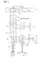
- Fig. 1 is a schematic sectional view of an optical pickup device relating to the First Embodiment capable of conducting recording and/or reproducing of information for all of high density DVD (which is also called a first optical disc), conventional DVD (which is also called a second optical disc) and CD (which is also called a third optical disc).
- high density DVD which is also called a first optical disc
- conventional DVD which is also called a second optical disc
- CD which is also called a third optical disc
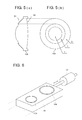
- Fig. 2 is a perspective view of an objective lens actuator device used for the optical pickup device of the present embodiment.
- Objective lens actuator device 10 shown in Fig. 2 is composed of objective lens 109 (first objective optical element) that is arranged on the optical pickup device shown in Fig.
- objective lens 209 (second objective optical element), lens holder 13 that holds optical axes of the objective lenses 109 and 209 on the same circumference 13A, chassis 15 that holds the lens holder 13 through supporting shaft 14 provided at the position of the central axis of the circumference 13A, rotatably and on a manner of movable back and forth along a central axis of the rotation, a focusing actuator (not shown) that makes the lens holder 13 to reciprocate in the direction along the supporting shaft 14 and tracking actuator 20 that urges the lens holder 13 to rotate for positioning each objective lens 109 and 209.
- an operation control circuit (not shown) that controls operation of each actuator.
- the objective lenses 109 and 209 are provided respectively in through holes formed on the flat surface of the lens holder 13, and they are arranged to be the same in terms of a distance from the center of the lens holder 13.
- the lens holder 13 is engaged rotatably, at its central portion, with the top end portion of the supporting shaft 14 studded on the chassis 15, and an unillustrated focusing actuator is provided on the lower portion of the supporting shaft 14.
- the focusing actuator 20 uses a permanent magnet provided on the lower end portion of the supporting shaft 14 and a coil provided around the permanent magnet to construct an electromagnetic solenoid, and by adjusting an electric current that flows through the coil, reciprocating movement in a microscopic unit in the direction (vertical direction in Fig. 2) along the supporting shaft 14 is urged for the supporting shaft 14 and lens holder 13, thus, a focal length is adjusted.
- the lens holder 13 is given rotating movements around the supporting shaft 14 having an axial line which is in parallel with an optical axis, by tracking actuator 20.
- This tracking actuator 20 is equipped with a pair of tracking coils 21A and 21B which are provided on the edge portion of the lens holder 13 to be symmetric with the supporting shaft 14 between, and with two pairs of magnets including a pair of magnets 22A and 22B and a pair of magnets 23A and 23B which are provided in the vicinity of the edge portion of the lens holder 13 to be symmetric with the supporting shaft 14 on the chassis 15 between.
- positions of the magnets 22A and 22B are established so that objective lens 109 may be on the optical path of the laser beam reflected on reflection mirror 16, while, when the tracking coils 21A and 21B face respectively the magnet 23A and the magnet 23B, positions of the magnets 23A and 23B are established so that objective lens 209 may be on the optical path of the laser beam.
- an unillustrated stopper which restricts a range of rotation so that the tracking coil 21A may not face the magnet 22B or magnet 23B and the tracking coil 21B may not face the magnet 22A or magnet 23A.
- the tracking actuator 20 is arranged so that the direction of a tangent on the outer circumferential surface of circular lens holder 13 may be perpendicular to the direction of a tangent on the track of an optical disc, and it is one for correcting the deviation of the irradiation position for the track of the laser beam, by urging rotating movements in a microscopic unit for the lens holder 13. Therefore, for conducting this tracking operation, it is necessary for each of tracking coils 21A and 21B to urge the lens holder 13 delicately to rotate while keeping the condition to face each of the magnets 22A and 22B.
- an arrangement wherein there is provided a piece of iron inside each of the tracking coils 21A and 21B, and an operation control circuit controls to flow an electric current through each of tracking coils 21A and 21B so that this piece of iron may produce delicate repulsive force between itself and each magnet while being attracted to each magnet.
- lens holder 13 of objective lens actuator mechanism 10 when conducting recording and/or reproducing of information for the first optical disc 110 and the second optical disc 110', lens holder 13 of objective lens actuator mechanism 10 is rotated, and objective lens 109 is inserted in an optical path as shown in Fig. 1. Namely, in the present embodiment, the objective lens 109 is used for the first optical disc 110 and the second optical disc 110' in common. Further, the first semiconductor laser 101 and the second semiconductor laser 201 are mounted on the same base board to constitute a single unit that is called the so-called two-laser one package.
- Beam expanders (106 and 107) wherein at least one (preferably, optical element 106) can move in the direction of an optical axis have functions to change (enlarges, in this case) a diameter of a light flux of the parallel light flux, and to correct chromatic aberration and spherical aberration.
- a diffractive structure diffractive ring-shaped zone
- the diffractive structure for correcting chromatic aberration may also be provided on another optical element (collimator 104), in addition to the optical element 107.
- the function to correct chromatic aberration can also be achieved by a phase structure or a multi-level, in place of the diffractive structure.
- chromatic aberration and spherical aberration can be corrected, and when high density DVD, for example, has two layers of information recording surfaces, it is also possible to select the information recording surface by moving the optical element 106 in the direction of an optical axis.
- a chromatic aberration correcting optical element and a means to control spherical aberration may also be objective lenses 109 (209) each having thereon a diffractive structure, without being the beam expanders (106 and 107).
- objective lens 109 it is possible to use an inexpensive plastic material as a material of the objective lens 109, although glass may also be used as a material, because deterioration by spherical aberration caused by environmental changes can be corrected optionally by beam expanders (106 and 107) and thereby a restriction for optical characteristics required can be eased.
- the light flux modulated by information pits and reflected on the information recording surface passes again through objective lens 109, diaphragm 108 and beam expanders (107 and 106), to be reflected on the second beam splitter 105, then, is given astigmatism by cylindrical lens 111, and passes through sensor lens 112 to enter a light-receiving surface of photodetector 113, and therefore, its output signals are used to obtain the scale reading of the information recorded on the first optical disc 110.
- a focusing actuator (not shown) and tracking actuator 20 of objective lens actuator mechanism 10 move the objective lens 109 solidly so that a light flux emitted from the first semiconductor laser 101 may form an image on an information recording surface of the first optical disc 110.
- the beam expanders (106 and 107) can correct chromatic aberration and spherical aberration.
- the collimator 104 serving as a means to restrict the numerical aperture
- a dichroic coat by restricting an area for a light flux to pass through in accordance with a wavelength
- a combination of the numerical apertures is not limited to the foregoing.
- the light flux modulated by information pits and reflected on the information recording surface passes again through objective lens 109, diaphragm 108 and beam expanders (107 and 106), to be reflected on the second beam splitter 105, then, is given astigmatism by cylindrical lens 111, and passes through sensor lens 112 to enter a light-receiving surface of photodetector 113, and therefore, its output signals are used to obtain the scale reading of the information recorded on the first optical disc 110.
- a focusing actuator (not shown) and tracking actuator 20 of objective lens actuator mechanism 10 move the objective lens 109 solidly so that a light flux emitted from the second semiconductor laser 201 may form an image on an information recording surface of the second optical disc 110'.
- lens holder 13 of the objective lens actuator mechanism 10 is rotated, and objective lens 209 is inserted in an optical path.
- objective lens 209 is used exclusively for the third optical disc 110''.
- beam expanders (106 and 107) can correct chromatic aberration and spherical aberration.
- the light flux modulated by information pits and reflected on the information recording surface passes again through objective lens 209, diaphragm 108, beam expanders (107 and 106), second beam splitter 105 and collimator 104 to be reflected on the first beam splitter 103, and then, is reflected on the third beam splitter 203, and is given astigmatism by cylindrical lens 204, and passes through sensor lens 205 to enter a light-receiving surface of photodetector 206, and therefore, its output signals are used to obtain the scale reading of the information recorded on the third optical disc 110''.
- a focusing actuator (not shown) and tracking actuator 20 of objective lens actuator mechanism 10 move the objective lens 209 solidly so that a light flux emitted from the third semiconductor laser 301 may form an image on an information recording surface of the third optical disc 110''.
- Fig. 3 is a schematic structural diagram of an optical pickup device relating to the Second Embodiment.
- lens holder 13 of objective lens actuator mechanism 10 is rotated, and objective lens 109 is inserted into an optical path as shown in Fig. 3.
- the objective lens 109 is used exclusively for the first optical disc 110.
- the second semiconductor laser 201 and the third semiconductor laser 301 are installed on the same base board to constitute a single unit that is called the so-called two-laser one package.
- Beam expanders (106 and 107) wherein at least one (preferably, optical element 106) can move in the direction of an optical axis have functions to change (enlarges, in this case) a diameter of a light flux of the parallel light flux, and to correct chromatic aberration and spherical aberration.
- objective lens 109 it is possible to use an inexpensive plastic material as a material of the objective lens 109, although glass may also be used as a material, because deterioration by spherical aberration caused by environmental changes can be corrected optionally by beam expanders (106 and 107) and thereby a restriction for optical characteristics required can be eased.
- the light flux modulated by information pits and reflected on the information recording surface passes again through objective lens 109, diaphragm 108 and beam expanders (107 and 106), to be reflected on the second beam splitter 105, then, is given astigmatism by cylindrical lens 111, and passes through sensor lens 112 to enter a light-receiving surface of photodetector 113, and therefore, its output signals are used to obtain the scale reading of the information recorded on the first optical disc 110.
- a focusing actuator (not shown) and tracking actuator 20 of objective lens actuator mechanism 10 move the objective lens 109 solidly so that a light flux emitted from the first semiconductor laser 101 may form an image on an information recording surface of the first optical disc 110.
- lens holder 13 of objective lens actuator mechanism 10 is rotated, and objective lens 209 is inserted into an optical path.
- the objective lens 209 is used for both of the second optical disc 110' and the third optical disc 110" in common.
- the beam expanders (106 and 107) can correct chromatic aberration and spherical aberration.
- the collimator 104 serving as a means to restrict the numerical aperture
- a dichroic coat by restricting an area for a light flux to pass through in accordance with a wavelength
- a combination of the numerical apertures is not limited to the foregoing.
- the light flux modulated by information pits and reflected on the information recording surface passes again through objective lens 209, diaphragm 108, beam expanders (107 and 106), second beam splitter 105 and collimator 104 to be reflected on the first beam splitter 103, and then, is reflected on the third beam splitter 203, and is given astigmatism by cylindrical lens 204, and passes through sensor lens 205 to enter a light-receiving surface of photodetector 206, and therefore, its output signals are used to obtain the scale reading of the information recorded on the second optical disc 110'.
- a focusing actuator (not shown) and tracking actuator 20 of objective lens actuator mechanism 10 move the objective lens 209 solidly so that a light flux emitted from the second semiconductor laser 201 may form an image on an information recording surface of the second optical disc 110'.
- beam expanders (106 and 107) can correct chromatic aberration and spherical aberration.
- the light flux modulated by information pits and reflected on the information recording surface passes again through objective lens 209, diaphragm 108, beam expanders (107 and 106), second beam splitter 105 and collimator 104 to be reflected on the first beam splitter 103, and then, is reflected on the third beam splitter 203, and is given astigmatism by cylindrical lens 204, and passes through sensor lens 205 to enter a light-receiving surface of photodetector 206, and therefore, its output signals are used to obtain the scale reading of the information recorded on the third optical disc 110''.
- a focusing actuator (not shown) and tracking actuator 20 of objective lens actuator mechanism 10 move the objective lens 209 solidly so that a light flux emitted from the third semiconductor laser 301 may form an image on an information recording surface of the third optical disc 110''.
- Fig. 4 is a schematic structural diagram of an optical pickup device relating to the Third Embodiment.
- lens holder 13 of objective lens actuator mechanism 10 is rotated, and objective lens 109 is inserted into an optical path as shown in Fig. 4, and objective lens 209 is inserted into an optical path when conducting recording and/or reproducing of information for the second optical disc 110' and the third optical disc 110''.
- the objective lens 109 is used exclusively for the first optical disc 110
- the objective lens 209 is used for both of the second optical disc 110' and the third optical disc 110" in common.
- the objective lens 109 it is also possible to make the objective lens 109 to be used in common for the first optical disc 110 and the second optical disc 110', and to make the objective lens 209 to be used exclusively for the third optical disc 110.
- the second semiconductor laser 201 and the third semiconductor laser 301 are installed on the same base board to constitute a single unit that is called the so-called three-laser one package.
- Each of light fluxes emitted respectively from first semiconductor laser 101, second semiconductor laser 201 and third semiconductor laser 301 is corrected by beam shaper 102 in terms of a beam shape, then, passes through first beam splitter 103, and is collimated by collimator 104 that is given a dichroic coat to become a parallel light flux, and after that, it passes through second beam splitter 105 and enters a beam expander having optical elements 106 and 107.
- Beam expanders (106 and 107) wherein at least one (preferably, optical element 106) can move in the direction of an optical axis have functions to change (enlarge, in this case) a diameter of a light flux of the parallel light flux, and to correct chromatic aberration and spherical aberration.
- a light flux which has passed through beam expanders (106 and 107) passes through diaphragm 108, and is converged, by objective lens 109 or 209 composed only of a refracting interface, on an information recording surface through a protective layer of each of the first optical disc 110, the second optical disc 110' and the third optical disc 110'', to form a light-converged spot.
- a light flux modulated by information pits and reflected on the information recording surface passes again through objective lens 109 or 209, diaphragm 108 and beam expanders (107 and 106), and then, is reflected on the second beam splitter 105, and is given astigmatism by cylindrical lens 111, and passes through sensor lens 112 to enter a light-receiving surface of photodetector 113, and therefore, its output signals are used to obtain the scale reading of the information recorded on the optical disc.
- a focusing actuator (not shown) and tracking actuator 20 of objective lens actuator mechanism 10 move the objective lens 109 or 209 solidly so that a light flux emitted from the semiconductor laser may form an image on an information recording surface of the optical disc.
- Example 1 described below is represented by an objective lens which is preferable as objective lens 109 of the optical pickup device shown in Figs. 1 and 4.
- the objective lens in the Example 1 is one which is used exclusively for high density DVD, and is composed of two plastic lenses including a negative lens and a positive lens, wherein each of the two plastic lenses converges a light flux having a wavelength of 405 nm that has passed through a beam expander for changing a diameter of the light flux on an information recording surface of the optical disc through a protective layer with a thickness of 0.1 mm, and a focal length is 1.76 mm and a numerical aperture is 0.85.
- Lens data thereof are shown in Table 1. Incidentally, hereafter (including the lens data), it is assumed that the exponent of 10 (for example, 2.5 x 10 -3 ) is represented by E (for example, 2.5 x E ⁇ 3).
- An aspheric surface of the objective lens of this kind can be expressed by the following Numeral 1 when the direction of an optical axis is represented by X axis, a height in the direction perpendicular to the optical axis is represented by h and a radius of curvature of an optical surface is represented by r.
- ⁇ represents a conic constant
- a 2i represents an aspheric surface coefficient.
- Example 2 described below is represented by an objective lens which is preferable as objective lens 109 of the optical pickup device shown in Figs. 3. Its lens data are shown in Table 2.
- the objective lens in the Example 2 is one which is used in common for high density DVD and DVD, and has a form of a sectional view shown in Fig. 5.
- the present objective lens includes, on optical surface S1, central area 1 including an optical axis, intermediate area 2 which is formed around the central area 1 to be a step and peripheral area 3 formed around the intermediate area 2, and a diffractive structure is formed on the peripheral area 3.
- the light flux which has passed through the central area 1 and the peripheral area 3 is used to conduct recording and/or reproducing of information
- the light flux which has passed through the central area 1 and the intermediate area 2 is used to conduct recording and/or reproducing of information.
- a diffractive structure formed on the optical surface is expressed by the optical path difference given to the transmission wavefront by the diffractive structure.
- the optical path difference of this kind is expressed by optical path difference function ⁇ b (mm) that is defined by the following Numeral 2 when h represents a height in the direction perpendicular to an optical axis, m represents the diffraction order, ⁇ represents a working wavelength (wavelength for emission from a semiconductor laser), ⁇ B represents a blazed wavelength and C represents a coefficient of an optical path difference function.
- the objective lens 109 it is also possible to make the objective lens 109 to be one with characteristics capable of conducting properly recording and/or reproducing of information for both of two types of high density DVDs (one is the first optical information recording medium wherein a thickness of a protective layer t1 is 0.1 mm, and the other is the fourth optical information recording medium wherein a thickness of a protective layer t4 is 0.6 mm).
- the objective lens actuator device may also be of the structure wherein lens holder 13' holding two objective lenses 109 and 209 is slid straight in the direction perpendicular to an optical axis by linear actuator 30 as shown in Fig. 6, without being limited to the structure shown in Fig. 2.
- lens holders 13 and 13' do not need to be solid, and separate members holding respectively objective lens 109 and objective lens 209 may be moved independently so that the objective lens on one side may be inserted in an optical path of the light-converging optical system.
- lens holder 13" holding two objective lenses 109 and 209 is made to move only in the tracking direction of optical disc 110, and at least objective lens 109 for high density DVD is made to be positioned on tracking line TL, thus, recording and/reproducing of high density information is made to be possible.
- objective lens 209 for DVD and/or CD has room in terms of design, and therefore, it makes it possible to conduct recording and/or reproducing of appropriate information, even when it is located at the position deviated from tracking line TL.
- the objective lens may also be composed of plural elements without being limited to a single element, and various materials such as glass and plastic may also be used for the material thereof.
- the invention make it possible to provide an optical pickup device that can conduct recording and/or reproducing of information properly for all of high density DVD, conventional DVD and CD, for example.
Landscapes
- Physics & Mathematics (AREA)
- Optics & Photonics (AREA)
- Engineering & Computer Science (AREA)
- Environmental & Geological Engineering (AREA)
- Health & Medical Sciences (AREA)
- Life Sciences & Earth Sciences (AREA)
- Hydrology & Water Resources (AREA)
- Public Health (AREA)
- Water Supply & Treatment (AREA)
- Optical Head (AREA)
- Lenses (AREA)
Applications Claiming Priority (2)
| Application Number | Priority Date | Filing Date | Title |
|---|---|---|---|
| JP2003095182 | 2003-03-31 | ||
| JP2003095182 | 2003-03-31 |
Publications (2)
| Publication Number | Publication Date |
|---|---|
| EP1465171A2 true EP1465171A2 (de) | 2004-10-06 |
| EP1465171A3 EP1465171A3 (de) | 2007-08-08 |
Family
ID=32844622
Family Applications (1)
| Application Number | Title | Priority Date | Filing Date |
|---|---|---|---|
| EP04101197A Ceased EP1465171A3 (de) | 2003-03-31 | 2004-03-23 | Optische Abtastvorrichtung und Objektivlinse dafür |
Country Status (6)
| Country | Link |
|---|---|
| US (1) | US7193954B2 (de) |
| EP (1) | EP1465171A3 (de) |
| JP (2) | JP2011023108A (de) |
| KR (1) | KR20040086751A (de) |
| CN (1) | CN100547663C (de) |
| TW (1) | TWI342017B (de) |
Cited By (4)
| Publication number | Priority date | Publication date | Assignee | Title |
|---|---|---|---|---|
| EP1732073A2 (de) * | 2005-06-07 | 2006-12-13 | Samsung Electronics Co., Ltd. | Optische Aufzeichnungs-/Wiedergabevorrichtung |
| EP1675110A3 (de) * | 2004-12-22 | 2007-01-17 | Samsung Electronics Co., Ltd. | Stellantrieb für optischen Lesekopf mit Aberrationskorrekturmechanismus und Montageverfahren dafür |
| EP1596383A3 (de) * | 2004-05-10 | 2007-11-07 | Konica Minolta Opto, Inc. | Optische Abtastvorrichtung |
| CN100428343C (zh) * | 2004-11-24 | 2008-10-22 | Lg电子有限公司 | 近场光学装置内跟踪伺服系统的控制装置及方法 |
Families Citing this family (20)
| Publication number | Priority date | Publication date | Assignee | Title |
|---|---|---|---|---|
| EP1471514A3 (de) * | 2003-04-22 | 2006-10-04 | Konica Minolta Opto, Inc. | Optische Abtastvorrichtung und Vorrichtung zur optischen Aufnahme und Wiedergabe von Information, Aufweitungslinse, Kopplungslinse und optisches Element zur Korrektur chromatischer Aberration |
| EP1647016A2 (de) * | 2003-07-07 | 2006-04-19 | Matsushita Electric Industrial Co., Ltd. | Objektivlinse, optische erfassungseinrichtung und optische platteneinrichtung |
| JPWO2005048250A1 (ja) * | 2003-11-14 | 2007-05-31 | コニカミノルタオプト株式会社 | 光ピックアップ装置及びそれに用いられる光学素子 |
| US20050247855A1 (en) * | 2004-04-27 | 2005-11-10 | Hiroaki Matsumiya | Optical pickup apparatus |
| JP2005327395A (ja) * | 2004-05-14 | 2005-11-24 | Sony Corp | 光ピックアップ及びこれを用いた記録及び/又は再生装置 |
| US7486592B2 (en) * | 2004-07-02 | 2009-02-03 | Industrial Technology Research Institute | Optical head having dual optical paths |
| TWI254293B (en) * | 2004-07-02 | 2006-05-01 | Ind Tech Res Inst | Optical read-write head |
| JP2006147053A (ja) * | 2004-11-19 | 2006-06-08 | Konica Minolta Opto Inc | 光ピックアップ装置 |
| JP2006147075A (ja) * | 2004-11-22 | 2006-06-08 | Hitachi Media Electoronics Co Ltd | 光ヘッドおよびそれを用いた光学的情報記録再生装置 |
| KR100680178B1 (ko) * | 2005-01-27 | 2007-02-08 | 삼성전자주식회사 | 광픽업 장치 |
| EP1866918A1 (de) * | 2005-02-25 | 2007-12-19 | Matsushita Electric Industrial Co., Ltd. | Optische abnehmervorrichtung |
| JP4476141B2 (ja) * | 2005-03-16 | 2010-06-09 | 三洋電機株式会社 | フォーカスサーボ導入装置 |
| WO2006112153A1 (ja) * | 2005-03-30 | 2006-10-26 | Pioneer Corporation | 光ピックアップ装置及び情報記録再生装置 |
| US7352517B2 (en) * | 2005-05-09 | 2008-04-01 | Konica Minolta Opto, Inc. | Optical pickup apparatus |
| US20070047424A1 (en) * | 2005-08-29 | 2007-03-01 | Konica Minolta Opto, Inc. | Objective lens unit, its manufacturing method and optical pick-up apparatus |
| JP2007073094A (ja) * | 2005-09-05 | 2007-03-22 | Konica Minolta Opto Inc | 光ピックアップ装置 |
| JP4499671B2 (ja) * | 2006-02-17 | 2010-07-07 | シャープ株式会社 | 光ピックアップ装置 |
| KR100903143B1 (ko) * | 2006-07-21 | 2009-06-16 | 삼성전자주식회사 | 대물렌즈와 이를 갖는 광 픽업장치 |
| CN101388259B (zh) * | 2007-09-11 | 2012-02-08 | 瑞鼎科技股份有限公司 | 光钳夹控制装置 |
| JP2009245539A (ja) * | 2008-03-31 | 2009-10-22 | Sony Corp | 光ディスク装置及びメディア種類判別方法 |
Citations (6)
| Publication number | Priority date | Publication date | Assignee | Title |
|---|---|---|---|---|
| EP1022731A2 (de) * | 1999-01-22 | 2000-07-26 | Konica Corporation | Optische Abtastvorrichtung und Verfahren zur Informationaufzeichnung und Informationswiedergabe |
| US6115192A (en) * | 1998-06-16 | 2000-09-05 | Siros Technologies, Inc. | Apparatus for adjustable spherical aberration correction |
| JP2000348376A (ja) * | 1999-03-31 | 2000-12-15 | Matsushita Electric Ind Co Ltd | 光ヘッド及び記録再生方法 |
| EP1184856A2 (de) * | 2000-08-08 | 2002-03-06 | SAMSUNG ELECTRONICS Co. Ltd. | Korrekturelement für Aberration und damit ausgerüstetes optisches Abtastgerät |
| WO2003005352A1 (en) * | 2001-07-05 | 2003-01-16 | Matsushita Electric Industrial Co., Ltd. | Optical disk device |
| US6650612B1 (en) * | 1999-03-31 | 2003-11-18 | Matsushita Electric Industrial Co., Ltd. | Optical head and recording reproduction method |
Family Cites Families (28)
| Publication number | Priority date | Publication date | Assignee | Title |
|---|---|---|---|---|
| US5729510A (en) * | 1994-01-19 | 1998-03-17 | Kabushiki Kaisha Toshiba | Optical head used for recording on optical recording medium having various thicknesses, warpage and the like |
| JPH09120559A (ja) * | 1995-10-24 | 1997-05-06 | Ricoh Co Ltd | 光学ヘッド装置 |
| US6016301A (en) * | 1996-04-01 | 2000-01-18 | Sony Corporation | Optical pickup device and optical disc reproducing apparatus |
| JP3845982B2 (ja) * | 1997-10-17 | 2006-11-15 | ソニー株式会社 | 光ピックアップ装置 |
| JPH11273092A (ja) * | 1998-01-20 | 1999-10-08 | Sony Corp | 光学ヘッド及び光ディスク装置 |
| KR19990074812A (ko) * | 1998-03-14 | 1999-10-05 | 윤종용 | 호환형 광픽업장치 |
| KR100278786B1 (ko) * | 1998-06-18 | 2001-01-15 | 구자홍 | 광기록매체와 광 기록/재생 방법 및 장치 |
| US6449235B1 (en) * | 1998-04-04 | 2002-09-10 | Lg Electronics, Inc. | Optical pick-up apparatus and optical recording/reproducing apparatus using the same |
| US6545958B1 (en) * | 1998-08-31 | 2003-04-08 | Ricoh Company, Ltd. | Optical-pickup device and tilt-detecting method thereof |
| JP2000231057A (ja) * | 1999-02-10 | 2000-08-22 | Konica Corp | 対物レンズ及び光ピックアップ装置 |
| TW432378B (en) * | 1999-04-13 | 2001-05-01 | Ind Tech Res Inst | A multiple-wavelength read/write pickup head for DVD |
| JP2001043559A (ja) * | 1999-07-30 | 2001-02-16 | Matsushita Electric Ind Co Ltd | 光ヘッド及び光ディスク装置 |
| JP4366813B2 (ja) * | 2000-02-23 | 2009-11-18 | コニカミノルタホールディングス株式会社 | 光ピックアップ装置及び光ピックアップ装置用のカップリングレンズ |
| EP1968054A3 (de) * | 2000-05-12 | 2012-03-07 | Konica Minolta Opto, Inc. | Optische Lesekopfvorrichtung |
| JP4660915B2 (ja) * | 2000-05-12 | 2011-03-30 | コニカミノルタホールディングス株式会社 | 光ピックアップ装置 |
| JP2002100061A (ja) * | 2000-09-22 | 2002-04-05 | Sony Corp | 光学ヘッド、光学式情報再生装置及び光学式情報記録装置 |
| JP4775610B2 (ja) * | 2000-10-26 | 2011-09-21 | コニカミノルタホールディングス株式会社 | 対物レンズ及び光ピックアップ装置 |
| JP4131366B2 (ja) * | 2000-10-30 | 2008-08-13 | コニカミノルタホールディングス株式会社 | 対物レンズ、光ピックアップ装置及び記録・再生装置 |
| JP4098989B2 (ja) * | 2001-03-09 | 2008-06-11 | ペンタックス株式会社 | 光ヘッド用対物レンズ |
| JP4621964B2 (ja) * | 2001-04-06 | 2011-02-02 | コニカミノルタホールディングス株式会社 | 光ピックアップ装置、記録・再生装置及び光ピックアップ装置における球面収差変動の補正方法 |
| JP2002334476A (ja) * | 2001-05-14 | 2002-11-22 | Konica Corp | 光ピックアップ装置及び記録・再生装置 |
| JP2002334475A (ja) * | 2001-05-14 | 2002-11-22 | Matsushita Electric Ind Co Ltd | 光ヘッドの球面収差補正装置 |
| EP1276104B1 (de) * | 2001-07-11 | 2011-01-26 | Konica Minolta Opto, Inc. | Optisches Korrekturelement für Aberration, optisches System, optisches Abtastgerät und Vorrichtung zur Aufzeichnung und Wiedergabe |
| JP2003059080A (ja) * | 2001-08-09 | 2003-02-28 | Matsushita Electric Ind Co Ltd | 光ヘッド装置及び光学情報記録再生装置 |
| JP4822037B2 (ja) * | 2001-08-24 | 2011-11-24 | コニカミノルタホールディングス株式会社 | 光ピックアップ装置の対物レンズ及び光ピックアップ装置 |
| JP2003077164A (ja) * | 2001-09-05 | 2003-03-14 | Konica Corp | 光ピックアップ光学系および光ピックアップ装置 |
| WO2003075267A1 (en) * | 2002-03-06 | 2003-09-12 | Matsushita Electric Industrial Co., Ltd. | Optical head device and optical information device using this, and computer, optical disk player, car navigation system, optical disy recorder and optical disk server using this optical information device |
| JP2003296959A (ja) * | 2002-03-26 | 2003-10-17 | Samsung Electro Mech Co Ltd | 波長選択性開口制限素子と波長選択性ビームスプリッタ及びそれを備えた光ピックアップ装置 |
-
2004
- 2004-03-22 US US10/805,730 patent/US7193954B2/en not_active Expired - Fee Related
- 2004-03-23 EP EP04101197A patent/EP1465171A3/de not_active Ceased
- 2004-03-26 TW TW093108399A patent/TWI342017B/zh not_active IP Right Cessation
- 2004-03-30 CN CNB2004100318754A patent/CN100547663C/zh not_active Expired - Fee Related
- 2004-03-30 KR KR1020040021409A patent/KR20040086751A/ko not_active Withdrawn
-
2010
- 2010-09-27 JP JP2010215155A patent/JP2011023108A/ja active Pending
-
2012
- 2012-07-23 JP JP2012162272A patent/JP2012198985A/ja active Pending
Patent Citations (7)
| Publication number | Priority date | Publication date | Assignee | Title |
|---|---|---|---|---|
| US6115192A (en) * | 1998-06-16 | 2000-09-05 | Siros Technologies, Inc. | Apparatus for adjustable spherical aberration correction |
| EP1022731A2 (de) * | 1999-01-22 | 2000-07-26 | Konica Corporation | Optische Abtastvorrichtung und Verfahren zur Informationaufzeichnung und Informationswiedergabe |
| JP2000348376A (ja) * | 1999-03-31 | 2000-12-15 | Matsushita Electric Ind Co Ltd | 光ヘッド及び記録再生方法 |
| US6650612B1 (en) * | 1999-03-31 | 2003-11-18 | Matsushita Electric Industrial Co., Ltd. | Optical head and recording reproduction method |
| EP1184856A2 (de) * | 2000-08-08 | 2002-03-06 | SAMSUNG ELECTRONICS Co. Ltd. | Korrekturelement für Aberration und damit ausgerüstetes optisches Abtastgerät |
| WO2003005352A1 (en) * | 2001-07-05 | 2003-01-16 | Matsushita Electric Industrial Co., Ltd. | Optical disk device |
| US20040218484A1 (en) * | 2001-07-05 | 2004-11-04 | Yuuichi Kuze | Optical disc device |
Non-Patent Citations (1)
| Title |
|---|
| MOORE S; GOLDSBERRY C: "FORMAT WAR PITS HD-DVD AGAINST BLUE-RAY DISC", MODERN PLASTICS INTERNATIONAL, vol. 60608, 1 November 2004 (2004-11-01), LAUSANNE, CH, pages 28 - 31, XP001204763, ISSN: 0026-8283 * |
Cited By (5)
| Publication number | Priority date | Publication date | Assignee | Title |
|---|---|---|---|---|
| EP1596383A3 (de) * | 2004-05-10 | 2007-11-07 | Konica Minolta Opto, Inc. | Optische Abtastvorrichtung |
| CN100428343C (zh) * | 2004-11-24 | 2008-10-22 | Lg电子有限公司 | 近场光学装置内跟踪伺服系统的控制装置及方法 |
| EP1675110A3 (de) * | 2004-12-22 | 2007-01-17 | Samsung Electronics Co., Ltd. | Stellantrieb für optischen Lesekopf mit Aberrationskorrekturmechanismus und Montageverfahren dafür |
| US7561498B2 (en) | 2004-12-22 | 2009-07-14 | Samsung Electronics Co., Ltd. | Optical pickup actuator having aberration correcting mechanism and method of assembling the same |
| EP1732073A2 (de) * | 2005-06-07 | 2006-12-13 | Samsung Electronics Co., Ltd. | Optische Aufzeichnungs-/Wiedergabevorrichtung |
Also Published As
| Publication number | Publication date |
|---|---|
| TWI342017B (en) | 2011-05-11 |
| JP2012198985A (ja) | 2012-10-18 |
| KR20040086751A (ko) | 2004-10-12 |
| JP2011023108A (ja) | 2011-02-03 |
| EP1465171A3 (de) | 2007-08-08 |
| US20040190423A1 (en) | 2004-09-30 |
| US7193954B2 (en) | 2007-03-20 |
| CN100547663C (zh) | 2009-10-07 |
| TW200501127A (en) | 2005-01-01 |
| CN1534641A (zh) | 2004-10-06 |
Similar Documents
| Publication | Publication Date | Title |
|---|---|---|
| EP1465171A2 (de) | Optische Abtastvorrichtung und Objektivlinse dafür | |
| CN100388371C (zh) | 校正波阵面错误的透镜及其光学拾取器和校正方法 | |
| US6285646B1 (en) | Optical pickup using objective lens compatible with a plurality of optical disks | |
| JP4660915B2 (ja) | 光ピックアップ装置 | |
| JP2004319062A (ja) | 光ピックアップ装置 | |
| WO2008075573A1 (ja) | 光ピックアップ装置用の光学素子、光ピックアップ装置及び光ピックアップ装置の組み立て方法 | |
| JP2002006210A (ja) | 光記録媒体用対物レンズおよびこれを用いた光ピックアップ装置 | |
| KR100509493B1 (ko) | 호환형 광픽업 | |
| US20050018585A1 (en) | Optical pickup device | |
| JP3972958B2 (ja) | 光ピックアップ装置 | |
| US20040184386A1 (en) | Optical pickup apparatus | |
| CN100394482C (zh) | 光拾取器及光盘驱动装置 | |
| JPWO2004097818A1 (ja) | 光ピックアップ装置 | |
| JP2006510151A (ja) | 光担体内に記憶されるデータの読み出し及び/又は書き込み用の光ヘッドを有する装置、及びこの装置に関する方法 | |
| US7671312B2 (en) | Optical pickup system, optical system, and optical information recording medium | |
| JP4383139B2 (ja) | 光ピックアップおよび光ディスク装置 | |
| JP2006252614A (ja) | 光ピックアップ装置およびこれを用いた光ディスクドライブ装置 | |
| JP3919171B2 (ja) | 対物レンズ駆動装置およびそれを備える光ピックアップ装置 | |
| EP1561211A1 (de) | Optisches abtastgerät | |
| JPH103686A (ja) | 情報ピックアップ装置及びその対物レンズ | |
| JP2006323917A (ja) | 対物レンズ及び光ピックアップ装置 | |
| JP2008152817A (ja) | 光学素子及び光ピックアップ装置 | |
| JP2004171771A (ja) | 情報ピックアップ装置及び光ディスク装置 | |
| JP2005108350A (ja) | 光ピックアップ装置、光ピックアップ装置の調整方法及び光情報記録再生装置 | |
| JP2006228368A (ja) | 対物レンズ、光ピックアップ装置及び光ディスク装置 |
Legal Events
| Date | Code | Title | Description |
|---|---|---|---|
| PUAI | Public reference made under article 153(3) epc to a published international application that has entered the european phase |
Free format text: ORIGINAL CODE: 0009012 |
|
| AK | Designated contracting states |
Kind code of ref document: A2 Designated state(s): AT BE BG CH CY CZ DE DK EE ES FI FR GB GR HU IE IT LI LU MC NL PL PT RO SE SI SK TR |
|
| AX | Request for extension of the european patent |
Extension state: AL LT LV MK |
|
| PUAL | Search report despatched |
Free format text: ORIGINAL CODE: 0009013 |
|
| AK | Designated contracting states |
Kind code of ref document: A3 Designated state(s): AT BE BG CH CY CZ DE DK EE ES FI FR GB GR HU IE IT LI LU MC NL PL PT RO SE SI SK TR |
|
| AX | Request for extension of the european patent |
Extension state: AL LT LV MK |
|
| 17P | Request for examination filed |
Effective date: 20080110 |
|
| AKX | Designation fees paid |
Designated state(s): BE DE FR GB NL |
|
| 17Q | First examination report despatched |
Effective date: 20080418 |
|
| STAA | Information on the status of an ep patent application or granted ep patent |
Free format text: STATUS: THE APPLICATION HAS BEEN REFUSED |
|
| 18R | Application refused |
Effective date: 20100101 |