EP1470973A2 - Vorrichtung zum Austausch von Daten, die teils repräsentativ für mindestens einen berechtigten Kraftfahrzeug-Benutzer sind - Google Patents
Vorrichtung zum Austausch von Daten, die teils repräsentativ für mindestens einen berechtigten Kraftfahrzeug-Benutzer sind Download PDFInfo
- Publication number
- EP1470973A2 EP1470973A2 EP04102330A EP04102330A EP1470973A2 EP 1470973 A2 EP1470973 A2 EP 1470973A2 EP 04102330 A EP04102330 A EP 04102330A EP 04102330 A EP04102330 A EP 04102330A EP 1470973 A2 EP1470973 A2 EP 1470973A2
- Authority
- EP
- European Patent Office
- Prior art keywords
- tunnel
- portable member
- portable
- vehicle
- blocking
- Prior art date
- Legal status (The legal status is an assumption and is not a legal conclusion. Google has not performed a legal analysis and makes no representation as to the accuracy of the status listed.)
- Granted
Links
Images


Classifications
-
- B—PERFORMING OPERATIONS; TRANSPORTING
- B60—VEHICLES IN GENERAL
- B60R—VEHICLES, VEHICLE FITTINGS, OR VEHICLE PARTS, NOT OTHERWISE PROVIDED FOR
- B60R25/00—Fittings or systems for preventing or indicating unauthorised use or theft of vehicles
- B60R25/20—Means to switch the anti-theft system on or off
- B60R25/2063—Ignition switch geometry
-
- B—PERFORMING OPERATIONS; TRANSPORTING
- B60—VEHICLES IN GENERAL
- B60R—VEHICLES, VEHICLE FITTINGS, OR VEHICLE PARTS, NOT OTHERWISE PROVIDED FOR
- B60R25/00—Fittings or systems for preventing or indicating unauthorised use or theft of vehicles
- B60R25/01—Fittings or systems for preventing or indicating unauthorised use or theft of vehicles operating on vehicle systems or fittings, e.g. on doors, seats or windscreens
- B60R25/04—Fittings or systems for preventing or indicating unauthorised use or theft of vehicles operating on vehicle systems or fittings, e.g. on doors, seats or windscreens operating on the propulsion system, e.g. engine or drive motor
-
- B—PERFORMING OPERATIONS; TRANSPORTING
- B60—VEHICLES IN GENERAL
- B60R—VEHICLES, VEHICLE FITTINGS, OR VEHICLE PARTS, NOT OTHERWISE PROVIDED FOR
- B60R25/00—Fittings or systems for preventing or indicating unauthorised use or theft of vehicles
- B60R25/20—Means to switch the anti-theft system on or off
- B60R25/24—Means to switch the anti-theft system on or off using electronic identifiers containing a code not memorised by the user
- B60R25/248—Electronic key extraction prevention
Definitions
- the present invention relates to an assembly for a motor vehicle intended for exchanging data, some of which are representative of at least one authorized vehicle user.
- the fixed data exchange unit is arranged in the passenger compartment of the vehicle and provides the anti-theft function by processing data including those representative of the authorized user.
- the fixed data exchange unit When the fixed data exchange unit has recognized the authorized user this starts the vehicle engine usually by means of a separate button of the fixed unit, arranged in a dashboard or a console in the passenger compartment.
- the vehicle starting operation therefore requires the introduction of the portable member in the tunnel of the fixed unit for user identification and actuation of the start button.
- the vehicle engine is also stopped using the start button.
- the object of the invention is in particular to simplify the starting operation of the vehicle and reduce the number of organs to handle to perform this operation.
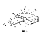
- FIG. 1 to 5 an assembly for the exchange of data according to the invention, designated by the general reference 10.
- This set includes a fixed data exchange unit 12 arranged in a motor vehicle, for example in a dashboard or a console the interior of this vehicle.
- the assembly 10 also includes a portable member 14 or badge intended to be housed in the fixed unit 12.
- the fixed unit 12 performs an anti-theft function by processing data, some, contained in the portable device, are representative of at least one user authorized vehicle. Representative user data is stored in the portable member 14 and processed by the fixed unit 12 using conventional means.
- an element is qualified as proximal when it is close to the hand of the user introducing the portable member into the fixed unit. Otherwise, the element is called distal.
- the general direction of movement of the portable member in the fixed unit is described as longitudinal.
- the fixed unit 12 has a general prismatic shape.
- the fixed unit 12 includes a support 16 housed in a housing 18.
- a printed circuit 20, carrying several conventional components, is fixed on the support 16, inside the housing 18.
- these conventional components in particular recognizes means of exchanging data with a transponder comprising an induction coil 22 intended to interact electromagnetically with complementary means arranged in the portable member.
- the fixed unit is provided with a tunnel 24 for housing the portable member 14 comprising parts proximal 24P and distal 24D separated by a movable flap 26.
- the latter is recalled elastically towards a position for closing the distal part 24D of the tunnel with a angular effect spring 27 illustrated in FIG. 2.
- the flap 26 is moved towards a open position to access the distal part 24D of the tunnel, against force elastic return spring 27, by cooperation with the distal end of the member portable 14 introduced into the tunnel.
- Each part 24P, 24D of the tunnel includes an end opposite the flap 26 which opens outwards from the fixed unit 12.
- the fixed unit 12 is usually arranged in the dashboard or the console of the passenger compartment so that hide from the user the open end of the distal part 24D of the tunnel.
- the through end of the proximal part 24D of the tunnel forms the end access to the tunnel through which the portable member 14 is introduced.
- the portable member 14 which is shown in more detail in Figures 6 to 8, has a generally thin prismatic shape bounded by two large longitudinal faces opposite F1, F2, two small longitudinal faces opposite F3, F4 and two small opposite transverse faces F5, F6 respectively delimiting the ends proximal and distal of the portable organ.
- the tunnel 24 has a general shape complementary to that of the organ portable 14.
- each part 24P, 24D of the tunnel is delimited by two large opposite longitudinal walls PD1, PD2, PP1, PP2 and two small walls longitudinal opposite PD3, PD4, PP3, PP4.
- the small longitudinal walls PD3, PD4, PP3, PP4 of each part 24P, 24D of the tunnel are parallel to the small faces F3, F4 of the portable member 14 when the latter is housed in the tunnel 24.
- the large longitudinal walls PD1, PD2, PP1, PP2 of each part 24P, 24D of the tunnel are adjacent to the small walls PD3, PD4, PP3, PP4 and therefore parallel to the large faces F1, F2 of the portable member 14 when the latter is housed in the tunnel 24.
- the proximal part 24P of the tunnel is delimited by a member translucent light scattering 28 clearly shown in Figures 2, 3, 6 and 7.
- a groove of guide 30 is provided on each small longitudinal face F3, F4 of the portable member 14. This groove 30 is intended to cooperate by fitting with a rib complementary guide 32 formed on a small longitudinal wall corresponding PD3, PD4 of the distal part 24D of the tunnel.
- Each small longitudinal wall PP1, PP2 of the proximal part 24P of the tunnel comprises a scraper finger 34 intended to cooperate with a guide groove corresponding 30 of the portable member 14.
- the scraper fingers 34 are preferably come of matter with the light diffusion member 28.
- each groove guide 30 of the portable member 14 is provided with a distal end 30D opening out and of a closed proximal end 30P delimited by a curving leave parallel to the large longitudinal faces F1, F2 of the portable member 14.
- the scraper fingers 34 are intended to prevent the penetration of dirt in the distal part 24D of the tunnel. Indeed, the scraper fingers 34, located upstream of the flap 26 relative to the direction of introduction of the portable member 14, are intended to cooperate by fitting with the grooves 30 of the portable member 14 so as to remove any dirt contained in these grooves 30, before the end distal of the portable member 14 crosses the flap 26. Under the effect of the scraping of the fingers 34, any dirt is pushed towards the proximal ends 30P of guide grooves, the leaves facilitating the removal of dirt from these grooves.
- the proximal end of the portable member 14, intended to grip this member 14, is permanently accessible from outside the tunnel 24, whatever its position in the tunnel.
- the grooves 30 of the portable member and the scraper fingers 34 of the tunnel form keying means preventing the user from entering by mistake the proximal end of the portable organ in the tunnel. Indeed, the ends proximal closed guide grooves 30 prevent the nesting of these grooves 30 with the scraper fingers 34 of the tunnel and therefore the incorrect introduction of the proximal end of the portable member in the tunnel 24.
- the grooves 30 cooperate first with the scraper fingers 34 then with the ribs 32 to guide this portable member 14 in the tunnel 24.
- the friction between the portable member 14 and the walls delimiting tunnel 24 are therefore essentially limited to friction between the surfaces delimiting, on the one hand the grooves 30 and, on the other hand, the scraper fingers 34 and the guide ribs 32. These small surfaces are few or no visible to the user which preserves the aesthetic appearance of the portable member 14 in the event of wear of the friction surfaces.
- the printed circuit 20 is separated from the internal volume of the tunnel 24 by the large longitudinal wall PD2 of the 24D distal part of the tunnel.
- the longitudinal dimension of this large PD2 wall is such that the portable member 14 is always separated from the printed circuit 20 by this large longitudinal wall PD2 whatever the position of the portable member 14 in the part distal 24D of the tunnel.
- the large wall PD2 separating the printed circuit 20 from the internal volume of the distal part of the tunnel 24 protects the printed circuit 20 from dirt possibly penetrating into the distal part 24D of the tunnel.
- the dirt present in the distal part 24D of the tunnel will be easily evacuated from this part 24D by the through end of the latter which is fully open towards the outside of the stationary unit 12. driven out of unit 12, through the through end of the part distal 24D of the tunnel, in particular by the displacement of the portable member 14 in the tunnel 24.
- the printed circuit 20 carries also three electrical contactors 36 to 40 arranged successively one behind the other with respect to the direction of introduction of the portable member 14 into the tunnel 24.
- These electrical contactors 36 to 40 are of the conventional push-button type.
- the first electrical contactor 36 considering the direction of introduction of the portable member 14 in the tunnel, is intended to activate a power-up state vehicle accessories.
- the second electrical contactor 38 is intended to activate a vehicle operating condition.
- the third electrical contactor 40 is intended to make start or stop the vehicle engine.
- the three electrical contactors will hereinafter called accessories 36, start 38 and start 40 contactors.
- the electrical contactors 36 to 40, external to tunnel 24, are intended for be actuated by the portable member 14 by means which will be described below.
- the contactor of accessories 36 is actuated via a control finger 42 making protrusion in the tunnel 24 through a small longitudinal wall PD3 delimiting the part 24D distal of this tunnel.
- the control finger 42 protrudes through the guide rib 32 of the small PD3 wall.
- the control finger 42 is intended to cooperate with a groove of corresponding guide 30 of the portable member 14.
- the control finger 42 forms therefore an intermediate return element allowing the portable member 14 to move in the tunnel 24 to activate the accessory switch 36 located outside of this tunnel 24.
- the portable member 14 can be moved longitudinally in the tunnel 24 from the access end of this tunnel to a stable position for actuating the travel switch 38, passing through an intermediate position, generally temporary, actuation of the accessory switch 36.
- the portable member 14 is maintained in its stable position actuation of the travel switch 38 by a blocking rocker 44 mounted rotating in the fixed unit 12 around an axis transverse to the longitudinal direction of displacement of the portable member 14.
- the blocking lever is provided with a part 44E external to tunnel 24 and a portion 44l internal to this tunnel 24 intended to cooperate with the portable member 14, more particularly with the edge of an orifice 46 of this member portable 14 opening into each of the large faces F1, F2 of this member 14.
- the blocking lever 44 extends opposite the printed circuit 20 with respect to in tunnel 24, the internal part 44l of the scale extending through the large wall longitudinal PD1 of tunnel 24 (see in particular Figure 4).
- the locking lever 44 is movable between two positions, respectively, of release of the portable member 14 and of cooperation with this portable member 14. In the latter position, the lever 44 blocks the portable member 14 in its stable position by fitting an arm of the internal part 44l of the rocker in the orifice 46 of this portable member.
- the blocking lever 44 is recalled towards each of these two positions release and cooperation with the portable member by a conventional bistable spring 48, for example in the general shape of a pin, as shown in FIGS. 2 and 3.
- the blocking lever 44 allows to obtain a swallowing effect on the portable member 14 when this member 14 reaches its stable position for actuating the contactor switch 38.
- Conventional means 50 with electromagnet form a removable stop preventing the return of the blocking lever 44 from its position of cooperation with the portable member 14 (corresponding to the stable position of the portable member 14) to its release position, in order to prevent the portable member 14 is inappropriately removed from the fixed unit 12 when the vehicle is in a state of market.
- These electromagnet means 50 are activated in a manner known per se, respectively deactivated, preferably when starting, respectively when stopping, of the vehicle engine.
- the portable member 14 can be moved longitudinally in the tunnel 24 to an unstable position for actuating the start switch 40 located beyond its stable position relative to the access end of tunnel 24. Between its stable and unstable positions, the portable member 14 is engaged with the internal part 441 of the rocker.
- the portable member 14 is recalled from its unstable position to its position stable by elastic means preferably comprising an effect spring 52 angular acting around the axis of rotation of the rocker 44.
- This return spring 52 illustrated in particular in FIGS. 2, 3 and 5, has also a thrust effect, parallel to the axis of rotation of the rocker 44, of so as to form an elastic spacer for axial positioning of the rocker 44.
- the return spring 52 is prestressed so as to exert on the rocker 44, when the portable member 14 is in its stable position, an opposite and greater effort to that of the bistable spring 48.
- the return spring 52 exerts a force two to three times greater than that of the bistable spring 48.
- the user introduces the portable member 14 into the access end of the tunnel 24 and pushes this portable member 14 towards the distal end of the tunnel 24.
- This stable position of the portable member 14 corresponds to a position of the cam 54 of the rocker in which this cam actuates the operation switch 38.
- the user pushes further the portable member 14 towards the distal end of the tunnel, by exerting on this portable member 14 sufficient effort to overcome the elastic return force of the spring 52.
- the portable member 14 then reaches its unstable position which is defined for example by the cooperation of complementary end-of-travel stops provided on the part internal 44l of the scale and the support 16 of the fixed unit 12.
- the unstable position of the portable member 14 corresponds to a position of the cam 54 of the rocker in which this cam actuates the start switch 40.
- the means 50 with electromagnet which prohibit the return of the blocking lever 44 towards its position for releasing the portable member, are activated.
- the user After starting the engine, the user releases the portable member 14 which is automatically returned by spring 52 to its stable on position of the vehicle. If the engine fails to start, the user pushes the portable device away 14 towards the distal end of the tunnel as many times as necessary to obtain the starting the vehicle.
- the portable member makes it possible to control the starting or stopping of the vehicle engine and thus avoid use an additional command button dedicated to these functions.
Landscapes
- Engineering & Computer Science (AREA)
- Mechanical Engineering (AREA)
- Lock And Its Accessories (AREA)
Applications Claiming Priority (3)
| Application Number | Priority Date | Filing Date | Title |
|---|---|---|---|
| FR0012259A FR2814418B1 (fr) | 2000-09-27 | 2000-09-27 | Ensemble pour vehicule automobile destine a echanger des donnees dont certaines sont representatives d'au moins un utilisateur autorise du vehicule |
| FR0012259 | 2000-09-27 | ||
| EP20010123009 EP1193147B1 (de) | 2000-09-27 | 2001-09-26 | Vorrichtung zum Austausch von Daten, die teils repräsentativ für mindestens einen berechtigten Kraftfahrzeug-Benutzer sind |
Related Parent Applications (1)
| Application Number | Title | Priority Date | Filing Date |
|---|---|---|---|
| EP20010123009 Division EP1193147B1 (de) | 2000-09-27 | 2001-09-26 | Vorrichtung zum Austausch von Daten, die teils repräsentativ für mindestens einen berechtigten Kraftfahrzeug-Benutzer sind |
Publications (4)
| Publication Number | Publication Date |
|---|---|
| EP1470973A2 true EP1470973A2 (de) | 2004-10-27 |
| EP1470973A3 EP1470973A3 (de) | 2005-05-11 |
| EP1470973B1 EP1470973B1 (de) | 2007-08-08 |
| EP1470973B8 EP1470973B8 (de) | 2008-08-20 |
Family
ID=8854710
Family Applications (2)
| Application Number | Title | Priority Date | Filing Date |
|---|---|---|---|
| EP04102330A Expired - Lifetime EP1470973B8 (de) | 2000-09-27 | 2001-09-26 | Vorrichtung zum Austausch von Daten, die teils repräsentativ für mindestens einen berechtigten Kraftfahrzeug-Benutzer sind |
| EP20010123009 Expired - Lifetime EP1193147B1 (de) | 2000-09-27 | 2001-09-26 | Vorrichtung zum Austausch von Daten, die teils repräsentativ für mindestens einen berechtigten Kraftfahrzeug-Benutzer sind |
Family Applications After (1)
| Application Number | Title | Priority Date | Filing Date |
|---|---|---|---|
| EP20010123009 Expired - Lifetime EP1193147B1 (de) | 2000-09-27 | 2001-09-26 | Vorrichtung zum Austausch von Daten, die teils repräsentativ für mindestens einen berechtigten Kraftfahrzeug-Benutzer sind |
Country Status (4)
| Country | Link |
|---|---|
| EP (2) | EP1470973B8 (de) |
| DE (2) | DE60103713T2 (de) |
| ES (2) | ES2222955T3 (de) |
| FR (1) | FR2814418B1 (de) |
Cited By (2)
| Publication number | Priority date | Publication date | Assignee | Title |
|---|---|---|---|---|
| DE102005009185A1 (de) * | 2005-03-01 | 2006-09-07 | Marquardt Gmbh | Zündstartschaltersystem für ein Kraftfahrzeug |
| DE102005062162A1 (de) * | 2005-12-22 | 2007-06-28 | Huf Hülsbeck & Fürst Gmbh & Co. Kg | Zünd-Anlaß-Schaltereinrichtung |
Families Citing this family (3)
| Publication number | Priority date | Publication date | Assignee | Title |
|---|---|---|---|---|
| DE102004013198A1 (de) * | 2003-03-22 | 2004-09-30 | Marquardt Gmbh | Zündschloßsystem für ein Kraftfahrzeug |
| DE10313376A1 (de) * | 2003-03-26 | 2004-10-07 | Leopold Kostal Gmbh & Co Kg | Anordnung zum Betätigen eines elektrischen Schalters |
| DE102009037580B4 (de) * | 2009-08-14 | 2023-05-17 | Volkswagen Ag | Verfahren zum Halten eines Schlüssels in einem Schloss für ein Fahrzeug, Verfahren zur Herstellung eines Fahrzeugs mit Zündschlüsselabzugssperre, Zündschlüsselabzugssperre und Fahrzeug |
Family Cites Families (8)
| Publication number | Priority date | Publication date | Assignee | Title |
|---|---|---|---|---|
| DE3206434A1 (de) * | 1982-02-23 | 1983-09-22 | Audi Nsu Auto Union Ag, 7107 Neckarsulm | Schliesssystem fuer kraftfahrzeuge |
| DE3306863C2 (de) * | 1983-02-26 | 1986-07-03 | Daimler-Benz Ag, 7000 Stuttgart | Schloßsystem für Kraftfahrzeuge, insbesondere Lenkschloßsystem |
| JPH10315914A (ja) * | 1997-05-19 | 1998-12-02 | Tokai Rika Co Ltd | 車両用始動装置 |
| FR2779563B1 (fr) | 1998-06-09 | 2001-01-19 | Valeo Securite Habitacle | Agencement pour le blocage longitudinal d'un support de donnees dans un dispositif d'echange de donnees |
| DE19836973B4 (de) * | 1998-08-14 | 2005-01-13 | Robert Bosch Gmbh | Zugangs- und Start-/Fahrberechtigungssystem für ein Fahrzeug |
| DE19853075A1 (de) * | 1998-11-17 | 2000-05-25 | Bosch Gmbh Robert | Fahrberechtigungssystem und entsprechendes Betriebsverfahren, insbesondere für Kraftfahrzeuge |
| FR2786297B1 (fr) | 1998-11-19 | 2001-01-19 | Valeo Securite Habitacle | Agencement pour le blocage d'un support de donnees dans un dispositif d'echange de donnees |
| DE19939733C2 (de) * | 1999-08-21 | 2001-10-11 | Huf Huelsbeck & Fuerst Gmbh | Vorrichtung zum Starten eines Fahrzeugmotors mittels eines elektronischen Schlüssels |
-
2000
- 2000-09-27 FR FR0012259A patent/FR2814418B1/fr not_active Expired - Fee Related
-
2001
- 2001-09-26 EP EP04102330A patent/EP1470973B8/de not_active Expired - Lifetime
- 2001-09-26 ES ES01123009T patent/ES2222955T3/es not_active Expired - Lifetime
- 2001-09-26 DE DE2001603713 patent/DE60103713T2/de not_active Expired - Lifetime
- 2001-09-26 EP EP20010123009 patent/EP1193147B1/de not_active Expired - Lifetime
-
2004
- 2004-05-27 ES ES04102330T patent/ES2291817T3/es not_active Expired - Lifetime
- 2004-05-27 DE DE2001629859 patent/DE60129859T2/de not_active Expired - Lifetime
Cited By (3)
| Publication number | Priority date | Publication date | Assignee | Title |
|---|---|---|---|---|
| DE102005009185A1 (de) * | 2005-03-01 | 2006-09-07 | Marquardt Gmbh | Zündstartschaltersystem für ein Kraftfahrzeug |
| DE102005009185B4 (de) * | 2005-03-01 | 2020-11-26 | Marquardt Gmbh | Zündstartschaltersystem für ein Kraftfahrzeug |
| DE102005062162A1 (de) * | 2005-12-22 | 2007-06-28 | Huf Hülsbeck & Fürst Gmbh & Co. Kg | Zünd-Anlaß-Schaltereinrichtung |
Also Published As
| Publication number | Publication date |
|---|---|
| ES2222955T3 (es) | 2005-02-16 |
| EP1470973B8 (de) | 2008-08-20 |
| EP1470973B1 (de) | 2007-08-08 |
| EP1193147B1 (de) | 2004-06-09 |
| DE60103713D1 (de) | 2004-07-15 |
| FR2814418B1 (fr) | 2003-02-07 |
| DE60103713T2 (de) | 2005-06-09 |
| EP1470973A3 (de) | 2005-05-11 |
| EP1193147A1 (de) | 2002-04-03 |
| FR2814418A1 (fr) | 2002-03-29 |
| ES2291817T3 (es) | 2008-03-01 |
| DE60129859D1 (de) | 2007-09-20 |
| DE60129859T2 (de) | 2008-04-30 |
Similar Documents
| Publication | Publication Date | Title |
|---|---|---|
| EP1611306B1 (de) | Schloss für eine öffnung an einem kraftfahrzeug mit einem gedächtnis zum entriegeln/verriegeln | |
| EP2621770B1 (de) | Lenkschloss für kraftfahrzeuge | |
| EP1020336A1 (de) | Kraftfahrzeuglenkungs- Diebstahlsicherung | |
| FR2948402A1 (fr) | Commande d'ouverture exterieure d'un ouvrant de vehicule automobile et ouvrant equipe d'une telle commande d'ouverture | |
| FR2877977A1 (fr) | Serrure de vehicule automobile | |
| EP1193147B1 (de) | Vorrichtung zum Austausch von Daten, die teils repräsentativ für mindestens einen berechtigten Kraftfahrzeug-Benutzer sind | |
| FR2958962A1 (fr) | Commande d'ouverture interieure d'un ouvrant de vehicule automobile et vehicule automobile equipee d'une telle commande. | |
| EP1193146B1 (de) | Vorrichtung zum Diebstahlschutz durch Austausch von Daten, die teils repräsentativ für mindestens einen berechtigten Kraftfahrzeug-Benutzer sind | |
| FR2943706A1 (fr) | Clef pour cylindre a pompes | |
| EP1193644B1 (de) | System zum Austausch von Daten zur Authorisation eines KFZ-Benutzers | |
| EP0706919B2 (de) | Lenkradschloss für Kraftfahrzeuge mit einem Automatikgetriebe | |
| WO2013014173A1 (fr) | Dispositif antivol pour colonne de direction et colonne de direction associée | |
| FR2814416A1 (fr) | Ensemble perfectionne pour vehicule automobile destine a echanger des donnees dont certaines sont representatives d'au moins un utilisateur autorise du vehicule | |
| EP3172092B1 (de) | Diebstahlsicherung für kraftfahrzeug | |
| EP1026350A1 (de) | Türgriff für Kraftfahrzeug | |
| EP2704926B1 (de) | Diebstahlschutzvorrichtung für lenksäule und entsprechende lenksäule | |
| EP0909862A1 (de) | Verbesserte motorisierte Vorrichtung zum Öffnen eines Kraftfahrzeugschlosses | |
| EP2503082B1 (de) | Motorised lock for automobile | |
| FR2743837A1 (fr) | Pene demi-tour pour serrure reversible et serrure reversible comportant un tel pene | |
| EP0913576B1 (de) | Steuerungsvorrichtung für die Stromversorgung eines Anlassers für ein Kraftfahrzeug und Antidiebstahlvorrichtung mit solcher Vorrichtung | |
| EP2460171B1 (de) | Anpassbarer zündschalter | |
| FR2466370A1 (fr) | Commutateur d'allumage de moteur a combustion interne de vehicules, avec dispositif d'interdiction de repetition du mouvement de demarrage | |
| EP1043204A1 (de) | Verbesserte Kraftfahrzeugdiebstahlsicherung | |
| FR2614588A1 (fr) | Dispositif de verrouillage et de deverrouillage d'arbre de direction pour vehicule automobile lie au commutateur d'allumage | |
| FR2893547A1 (fr) | Trappe pour un vehicule automobile |
Legal Events
| Date | Code | Title | Description |
|---|---|---|---|
| PUAI | Public reference made under article 153(3) epc to a published international application that has entered the european phase |
Free format text: ORIGINAL CODE: 0009012 |
|
| AC | Divisional application: reference to earlier application |
Ref document number: 1193147 Country of ref document: EP Kind code of ref document: P |
|
| AK | Designated contracting states |
Kind code of ref document: A2 Designated state(s): DE ES FR GB IT |
|
| RAP1 | Party data changed (applicant data changed or rights of an application transferred) |
Owner name: VALEO SECURITE HABITACLE S.A.S. |
|
| PUAL | Search report despatched |
Free format text: ORIGINAL CODE: 0009013 |
|
| AK | Designated contracting states |
Kind code of ref document: A3 Designated state(s): DE ES FR GB IT |
|
| 17P | Request for examination filed |
Effective date: 20051111 |
|
| AKX | Designation fees paid |
Designated state(s): DE ES FR GB IT |
|
| GRAP | Despatch of communication of intention to grant a patent |
Free format text: ORIGINAL CODE: EPIDOSNIGR1 |
|
| GRAS | Grant fee paid |
Free format text: ORIGINAL CODE: EPIDOSNIGR3 |
|
| GRAA | (expected) grant |
Free format text: ORIGINAL CODE: 0009210 |
|
| AC | Divisional application: reference to earlier application |
Ref document number: 1193147 Country of ref document: EP Kind code of ref document: P |
|
| AK | Designated contracting states |
Kind code of ref document: B1 Designated state(s): DE ES FR GB IT |
|
| REG | Reference to a national code |
Ref country code: GB Ref legal event code: FG4D Free format text: NOT ENGLISH |
|
| REF | Corresponds to: |
Ref document number: 60129859 Country of ref document: DE Date of ref document: 20070920 Kind code of ref document: P |
|
| GBT | Gb: translation of ep patent filed (gb section 77(6)(a)/1977) |
Effective date: 20071101 |
|
| REG | Reference to a national code |
Ref country code: ES Ref legal event code: FG2A Ref document number: 2291817 Country of ref document: ES Kind code of ref document: T3 |
|
| PLBE | No opposition filed within time limit |
Free format text: ORIGINAL CODE: 0009261 |
|
| STAA | Information on the status of an ep patent application or granted ep patent |
Free format text: STATUS: NO OPPOSITION FILED WITHIN TIME LIMIT |
|
| 26N | No opposition filed |
Effective date: 20080509 |
|
| PG25 | Lapsed in a contracting state [announced via postgrant information from national office to epo] |
Ref country code: DE Free format text: LAPSE BECAUSE OF NON-PAYMENT OF DUE FEES Effective date: 20071203 |
|
| GBTC | Gb: corrected translation (of ep patent) filed (gb section 80(3)/1977) |
Effective date: 20071231 |
|
| PG25 | Lapsed in a contracting state [announced via postgrant information from national office to epo] |
Ref country code: IT Free format text: LAPSE BECAUSE OF NON-PAYMENT OF DUE FEES Effective date: 20070926 |
|
| REG | Reference to a national code |
Ref country code: FR Ref legal event code: PLFP Year of fee payment: 16 |
|
| REG | Reference to a national code |
Ref country code: FR Ref legal event code: PLFP Year of fee payment: 17 |
|
| REG | Reference to a national code |
Ref country code: FR Ref legal event code: PLFP Year of fee payment: 18 |
|
| PGFP | Annual fee paid to national office [announced via postgrant information from national office to epo] |
Ref country code: FR Payment date: 20180928 Year of fee payment: 18 Ref country code: IT Payment date: 20180907 Year of fee payment: 18 Ref country code: DE Payment date: 20180913 Year of fee payment: 18 |
|
| PGFP | Annual fee paid to national office [announced via postgrant information from national office to epo] |
Ref country code: GB Payment date: 20180919 Year of fee payment: 18 |
|
| PGFP | Annual fee paid to national office [announced via postgrant information from national office to epo] |
Ref country code: ES Payment date: 20181023 Year of fee payment: 18 |
|
| REG | Reference to a national code |
Ref country code: DE Ref legal event code: R119 Ref document number: 60129859 Country of ref document: DE |
|
| PG25 | Lapsed in a contracting state [announced via postgrant information from national office to epo] |
Ref country code: DE Free format text: LAPSE BECAUSE OF NON-PAYMENT OF DUE FEES Effective date: 20200401 |
|
| PG25 | Lapsed in a contracting state [announced via postgrant information from national office to epo] |
Ref country code: IT Free format text: LAPSE BECAUSE OF NON-PAYMENT OF DUE FEES Effective date: 20190926 |
|
| GBPC | Gb: european patent ceased through non-payment of renewal fee |
Effective date: 20190926 |
|
| PG25 | Lapsed in a contracting state [announced via postgrant information from national office to epo] |
Ref country code: FR Free format text: LAPSE BECAUSE OF NON-PAYMENT OF DUE FEES Effective date: 20190930 Ref country code: GB Free format text: LAPSE BECAUSE OF NON-PAYMENT OF DUE FEES Effective date: 20190926 |
|
| REG | Reference to a national code |
Ref country code: ES Ref legal event code: FD2A Effective date: 20210129 |
|
| PG25 | Lapsed in a contracting state [announced via postgrant information from national office to epo] |
Ref country code: ES Free format text: LAPSE BECAUSE OF NON-PAYMENT OF DUE FEES Effective date: 20190927 |