EP1479916B1 - Machine à spirales pour fluides - Google Patents
Machine à spirales pour fluides Download PDFInfo
- Publication number
- EP1479916B1 EP1479916B1 EP04011852A EP04011852A EP1479916B1 EP 1479916 B1 EP1479916 B1 EP 1479916B1 EP 04011852 A EP04011852 A EP 04011852A EP 04011852 A EP04011852 A EP 04011852A EP 1479916 B1 EP1479916 B1 EP 1479916B1
- Authority
- EP
- European Patent Office
- Prior art keywords
- scroll
- gas
- driving shaft
- heat
- orbiting
- Prior art date
- Legal status (The legal status is an assumption and is not a legal conclusion. Google has not performed a legal analysis and makes no representation as to the accuracy of the status listed.)
- Expired - Lifetime
Links
- 239000012530 fluid Substances 0.000 title claims abstract description 22
- 230000003578 releasing effect Effects 0.000 claims abstract description 11
- 238000001816 cooling Methods 0.000 claims description 13
- IJGRMHOSHXDMSA-UHFFFAOYSA-N Atomic nitrogen Chemical compound N#N IJGRMHOSHXDMSA-UHFFFAOYSA-N 0.000 description 10
- 239000007789 gas Substances 0.000 description 8
- 230000006835 compression Effects 0.000 description 6
- 238000007906 compression Methods 0.000 description 6
- 229910052757 nitrogen Inorganic materials 0.000 description 5
- 238000012856 packing Methods 0.000 description 4
- 239000000463 material Substances 0.000 description 2
- 230000004323 axial length Effects 0.000 description 1
- 230000008859 change Effects 0.000 description 1
- 239000004020 conductor Substances 0.000 description 1
- 238000011109 contamination Methods 0.000 description 1
- 238000006073 displacement reaction Methods 0.000 description 1
- 230000000694 effects Effects 0.000 description 1
- 239000004519 grease Substances 0.000 description 1
- 239000010687 lubricating oil Substances 0.000 description 1
- 230000007246 mechanism Effects 0.000 description 1
- 238000012986 modification Methods 0.000 description 1
- 230000004048 modification Effects 0.000 description 1
- 239000011295 pitch Substances 0.000 description 1
- 239000000126 substance Substances 0.000 description 1
- 231100000331 toxic Toxicity 0.000 description 1
- 230000002588 toxic effect Effects 0.000 description 1
- 231100000419 toxicity Toxicity 0.000 description 1
- 230000001988 toxicity Effects 0.000 description 1
Images
Classifications
-
- F—MECHANICAL ENGINEERING; LIGHTING; HEATING; WEAPONS; BLASTING
- F04—POSITIVE - DISPLACEMENT MACHINES FOR LIQUIDS; PUMPS FOR LIQUIDS OR ELASTIC FLUIDS
- F04C—ROTARY-PISTON, OR OSCILLATING-PISTON, POSITIVE-DISPLACEMENT MACHINES FOR LIQUIDS; ROTARY-PISTON, OR OSCILLATING-PISTON, POSITIVE-DISPLACEMENT PUMPS
- F04C29/00—Component parts, details or accessories of pumps or pumping installations, not provided for in groups F04C18/00 - F04C28/00
- F04C29/04—Heating; Cooling; Heat insulation
Definitions
- the present invention relates to a scroll fluid machine, and particularly to a scroll fluid machine, such as a scroll vacuum pump or a scroll pressurizing machine, in which a fixed wrap of a fixed scroll in a housing is engaged with an orbiting wrap of an orbiting scroll rotatably connected to an eccentric axial portion of a driving shaft, the orbiting scroll being revolved at a certain eccentricity by the driving shaft, thereby compressing a gas sucked from the circumference or the center of the housing as it moves toward the center or circumference and being discharged.
- a scroll fluid machine such as a scroll vacuum pump or a scroll pressurizing machine
- Such a scroll fluid machine is known among persons skilled in the art.
- EP 0902186 discloses a scroll-type fluid displacement machine
- EP 0777053 discloses a scroll fluid machine.
- a scroll fluid machine runs for a long time, so that temperatures of a driving shaft, an eccentric axial portion of the driving shaft, bearings and packings rise which can result in damage in the bearings and packings or in leak of lubricating oil. Hence in time the machine becomes impossible to use.
- a gas-guiding bore is axially formed in a driving shaft, and low or room temperature air or nitrogen is discharged through the gas-guiding bore by centrifugal force caused by rotation of the driving shaft to cool bearings.
- a toxic or foreign-substance-containing gas in a compressing portion runs back and is discharged to atmosphere through the gas-guiding bore, thereby causing contamination in atmosphere.
- a scroll fluid machine comprising:
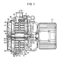
- Fig. 1 is a vertical sectional side view of one embodiment of a scroll fluid machine or a scroll vacuum pump according to the present invention, in which an orbiting scroll is revolved at a certain eccentricity, so that a gas through the circumference of a housing is sucked into a compressing portion between the orbiting scroll and a fixed scroll, compressed as it moves toward the center and discharged through the center.
- the numeral 1 denotes a housing having a closed disc-like compression chamber 2, and comprises a casing 3 and a cover 4, a sucking bore 1a being formed on the circumference.
- the housing 3 and cover 4 have fixed end plates 3a and 4a which surround the compression chamber 2 and oppose each other. Fixed wraps 3b and 4b are provided towards the compression chamber 2 to form the fixed scrolls 3c and 4c.
- a plurality of cooling radial fins 3d and 4d are provided on the outer sides of the fixed end plates 4a and 4a. Between the fixed end plates 3a and 4a in the compression chamber 2, the orbiting scroll 5 is provided to revolve around an axis of the compression chamber 2.
- the orbiting scroll 5 has an orbiting end plate 5a each surface of which has orbiting wraps 5b,5b engaged with the fixed scrolls 3c,4c, deviating by 180 degrees, and is rotatably supported on an eccentric axial portion 8a of a driving shaft 8 via a needle bearing 9 and a packing 9a.
- the driving shaft 8 is provided with bearings 6,7 in the center of the housing 1.
- the orbiting end plate 5a is engaged with the fixed end plate 3a via three known pin-crank rotation preventing mechanisms 10 spaced uniformly on the circumference. As the driving shaft 8 rotates, the orbiting end plate 5a eccentrically revolves in the compression chamber 2 to change a radial space between the fixed wraps 3b,4b and orbiting wraps 5b,5b engaged with each other.
- a plurality of axial gas-guiding bores 11,11 are formed near the center of the orbiting end plate 5a.
- the gas-guiding bore 11 above the eccentric axial portion 8a functions as compressed gas path and communicates at one end with a discharge bore 13 formed inwardly from the circumference of the fixed end plate 3a via an axial communicating bore 12 near the center of the fixed end plate 3a
- the driving shaft 8 has cooling fans 15,16 at the ends which extend from the fixed end plates 3a,4a.
- the cooling fans 15,15 suck air towards the center via the fins 3d,4d and discharge it away from the center.
- the orbiting scroll 5 rotatably mounted to the driving shaft 8 is revolved at a certain eccentricity while it is engaged with the fixed scroll 3c,4c, and air sucked through the sucking bore 1 a is compressed as it comes towards the center, thereby raising temperature.
- the inner ends of the heat pipes 14,14 in the gas-guiding bore 11 near the center of the orbiting scroll 5 are heated.
- the outer ends of the heat pipes 14,14 are projected from the fixed scrolls 3c,4c and cooled with the cooling fans 15,16 by air which flows via the cooling fins 3d,4d and circulates. So heat in the inner end of the heat pipe 14 or the orbiting scroll 5 is effectively released, thereby preventing excessive rise in temperature at the center of the orbiting scroll 5. Furthermore, the needle bearing 9 and packing 9a are not damaged with heat and enclosed grease is prevented
- heat-releasing rod, tube or plate made of high heat-conductive material such as Cu is made as heat-releasing rod and inserted into the gas-guiding bore 11.
- the outer ends are projected from the fixed end plates 3a and 4a and cooled with atmosphere.
- the projecting portions of the rod-like releasing material from the fixed end plates 3a,4a are made as flat as possible or as thin as possible, or a number of notches or wave-shape is formed to increase heat releasing effect.
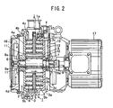
- Fig. 2 illustrates another embodiment of a scroll fluid machine, in which the same numerals are allotted to the same members as those in Fig. 1 and description therefor is omitted.
- Fig. 2 With nothing in a gas-guiding bore 11, cooling fans 15,16 with opposite pitches are rotated by a motor 17 to generate gas flow in a certain axial direction. Air is sucked from one end of the gas-guiding bore 11 by cooling fans 15,15 and discharged through the other end of the gas-guiding bore 11 after the gas-guiding bore 11 is effectively cooled.
- a heat pipe 14 or heat-releasing material as above is provided in the gas-guiding bore 11 thereby achieving more advantageous effect.
- the foregoing embodiments relate to a both-side scroll fluid machine in which both-side orbiting scrolls are provided between two fixed scrolls, but the present invention may also be applied to a one-side scroll fluid machine in which a one-side orbiting scroll is engaged with a one side fixed scroll.
Landscapes
- Engineering & Computer Science (AREA)
- Mechanical Engineering (AREA)
- General Engineering & Computer Science (AREA)
- Rotary Pumps (AREA)
- Applications Or Details Of Rotary Compressors (AREA)
- Structures Of Non-Positive Displacement Pumps (AREA)
Claims (4)
- Machine à spirales pour fluides comprenant :un carter (1) ;un arbre d'entraînement (8) comportant une section axiale excentrique (8a) ;une spirale fixe (3c, 4c) comportant un enroulement fixe (3b, 4b) dans le carter ;une spirale tournante (5) comportant un enroulement tournant (5b) ;un palier qui est monté entre la spirale tournante (5) et la section axiale excentrique (8a) de l'arbre d'entraînement afin de permettre à la spirale tournante de tourner autour de la section axiale excentrique (8a) grâce à l'arbre d'entraînement (8) de sorte qu'un gaz lequel est aspiré à travers une circonférence du carter (1) subisse une compression au fur et à mesure qu'il se déplace vers un centre de la spirale tournante (5), et soit déchargé ; caractérisée parun alésage de guidage de gaz (11) lequel est formé dans le plan axial dans la spirale tournante (5) à proximité du palier (9) et radialement à l'extérieur de ce dernier, et un ventilateur de refroidissement dont la rotation est assurée par l'arbre d'entraînement (8) proche d'un côté ouvert de l'alésage de guidage de gaz (11), ce qui permet au flux d'air généré par le ventilateur de refroidissement de passer à travers l'alésage de guidage de gaz (11) dans le but de réduire le transfert thermique du gaz comprimé vers le palier (9) pour refroidir le palier.
- Machine à spirales pour fluides, selon la revendication 1, dans laquelle le palier (9) comprend un palier à aiguilles.
- Machine à spirales pour fluides, selon la revendication 1 ou 2, dans laquelle une tige de dégagement de chaleur (14) est introduite dans l'alésage de guidage de gaz (11), l'une des extrémités de la tige de dégagement de chaleur (14) étant projetée depuis la spirale fixe (3c, 4c) afin d'évacuer la chaleur à l'atmosphère.
- Machine à spirales pour fluides, selon la revendication 3, dans laquelle la tige de dégagement de chaleur (14) comprend un tube de chaleur.
Applications Claiming Priority (2)
| Application Number | Priority Date | Filing Date | Title |
|---|---|---|---|
| JP2003146608A JP4373130B2 (ja) | 2003-05-23 | 2003-05-23 | スクロール流体機械 |
| JP2003146608 | 2003-05-23 |
Publications (2)
| Publication Number | Publication Date |
|---|---|
| EP1479916A1 EP1479916A1 (fr) | 2004-11-24 |
| EP1479916B1 true EP1479916B1 (fr) | 2008-09-03 |
Family
ID=33095498
Family Applications (1)
| Application Number | Title | Priority Date | Filing Date |
|---|---|---|---|
| EP04011852A Expired - Lifetime EP1479916B1 (fr) | 2003-05-23 | 2004-05-19 | Machine à spirales pour fluides |
Country Status (6)
| Country | Link |
|---|---|
| US (2) | US7121816B2 (fr) |
| EP (1) | EP1479916B1 (fr) |
| JP (1) | JP4373130B2 (fr) |
| CN (1) | CN100340772C (fr) |
| AT (1) | ATE407295T1 (fr) |
| DE (1) | DE602004016250D1 (fr) |
Families Citing this family (28)
| Publication number | Priority date | Publication date | Assignee | Title |
|---|---|---|---|---|
| DE3333678A1 (de) * | 1983-09-17 | 1985-03-28 | Basf Ag, 6700 Ludwigshafen | Verfahren zur herstellung von 3-formyl-tetrahydrothiopyranen |
| JP4629546B2 (ja) * | 2005-09-30 | 2011-02-09 | アネスト岩田株式会社 | スクロール流体機械 |
| JP2007198153A (ja) * | 2006-01-24 | 2007-08-09 | Anest Iwata Corp | スクロール流体機械 |
| JP4768457B2 (ja) * | 2006-01-27 | 2011-09-07 | アネスト岩田株式会社 | スクロール流体機械 |
| JP5020628B2 (ja) | 2006-12-26 | 2012-09-05 | アネスト岩田株式会社 | スクロール流体機械 |
| US8459971B2 (en) * | 2008-09-26 | 2013-06-11 | Honda Motor Co., Ltd. | Scroll compressor with balancer and oil passages |
| US8177534B2 (en) * | 2008-10-30 | 2012-05-15 | Advanced Scroll Technologies (Hangzhou), Inc. | Scroll-type fluid displacement apparatus with improved cooling system |
| JP2011004467A (ja) * | 2009-06-16 | 2011-01-06 | Panasonic Corp | モータおよびそれを用いた電子機器 |
| JP2011080366A (ja) * | 2009-10-02 | 2011-04-21 | Anest Iwata Corp | モータ直結型圧縮機ユニット |
| JP5109042B2 (ja) * | 2010-09-07 | 2012-12-26 | 株式会社リッチストーン | スクロール流体機械 |
| CN102071973B (zh) * | 2011-01-07 | 2012-12-19 | 山东科技大学 | 用于压缩空气储能技术的涡旋式压缩-膨胀复合机 |
| KR101462941B1 (ko) * | 2012-03-07 | 2014-11-19 | 엘지전자 주식회사 | 횡형 스크롤 압축기 |
| JP5998028B2 (ja) * | 2012-11-30 | 2016-09-28 | 株式会社日立産機システム | スクロール式流体機械 |
| US10208753B2 (en) | 2013-03-29 | 2019-02-19 | Agilent Technologies, Inc. | Thermal/noise management in a scroll pump |
| US9611852B2 (en) * | 2013-03-29 | 2017-04-04 | Agilent Technology, Inc. | Thermal/noise management in a scroll pump |
| CN103306973A (zh) * | 2013-05-29 | 2013-09-18 | 沈阳纪维应用技术有限公司 | 一种无油涡旋流体机械装置 |
| US10865793B2 (en) | 2016-12-06 | 2020-12-15 | Air Squared, Inc. | Scroll type device having liquid cooling through idler shafts |
| US11865820B2 (en) | 2017-12-19 | 2024-01-09 | Saint-Gobain Adfors Canada, Ltd. | Reinforcing layer, a cementitious board, and method of forming the cementitious board |
| EP3788262B1 (fr) | 2018-05-04 | 2024-11-20 | Air Squared, Inc. | Refroidissement par liquide de compresseur, de détendeur ou de pompe à vide à volute fixe et orbitale |
| US11067080B2 (en) * | 2018-07-17 | 2021-07-20 | Air Squared, Inc. | Low cost scroll compressor or vacuum pump |
| US20200025199A1 (en) | 2018-07-17 | 2020-01-23 | Air Squared, Inc. | Dual drive co-rotating spinning scroll compressor or expander |
| US11530703B2 (en) | 2018-07-18 | 2022-12-20 | Air Squared, Inc. | Orbiting scroll device lubrication |
| US11473572B2 (en) | 2019-06-25 | 2022-10-18 | Air Squared, Inc. | Aftercooler for cooling compressed working fluid |
| CN110319002B (zh) * | 2019-06-25 | 2020-08-18 | 珠海格力电器股份有限公司 | 压缩机 |
| US11898557B2 (en) | 2020-11-30 | 2024-02-13 | Air Squared, Inc. | Liquid cooling of a scroll type compressor with liquid supply through the crankshaft |
| US11885328B2 (en) | 2021-07-19 | 2024-01-30 | Air Squared, Inc. | Scroll device with an integrated cooling loop |
| US12510080B2 (en) * | 2022-12-15 | 2025-12-30 | Agilent Technologies, Inc. | Fluid pump and enclosure providing stator holder and cooling for motor and electronics |
| US20250020137A1 (en) * | 2023-06-09 | 2025-01-16 | Scott Fetzer/Powerex-Iwata Air Technology Inc. | Cooling attachment system for compressor motor assembly |
Family Cites Families (10)
| Publication number | Priority date | Publication date | Assignee | Title |
|---|---|---|---|---|
| US3842596A (en) * | 1970-07-10 | 1974-10-22 | V Gray | Methods and apparatus for heat transfer in rotating bodies |
| JPS5835389A (ja) * | 1981-08-26 | 1983-03-02 | Hisateru Akachi | 回転式ヒ−トパイプとその製造方法 |
| DE3810052A1 (de) * | 1987-04-08 | 1988-10-20 | Volkswagen Ag | Kuehlanordnung |
| US5101888A (en) * | 1990-12-03 | 1992-04-07 | Rockwell International Corporation | Heat pipe systems |
| US5417554A (en) * | 1994-07-19 | 1995-05-23 | Ingersoll-Rand Company | Air cooling system for scroll compressors |
| JP3423514B2 (ja) * | 1995-11-30 | 2003-07-07 | アネスト岩田株式会社 | スクロール流体機械 |
| JPH1026090A (ja) * | 1996-07-08 | 1998-01-27 | Asuka Japan:Kk | 通風冷却式スクロール流体機械 |
| JP3478940B2 (ja) * | 1997-03-04 | 2003-12-15 | 株式会社日立産機システム | スクロール圧縮機 |
| JPH1182333A (ja) * | 1997-09-12 | 1999-03-26 | Kimie Nakamura | スクロール流体機械 |
| JP2000345972A (ja) * | 1999-06-07 | 2000-12-12 | Hitachi Ltd | 両歯式スクロール圧縮機 |
-
2003
- 2003-05-23 JP JP2003146608A patent/JP4373130B2/ja not_active Expired - Fee Related
-
2004
- 2004-05-19 AT AT04011852T patent/ATE407295T1/de not_active IP Right Cessation
- 2004-05-19 EP EP04011852A patent/EP1479916B1/fr not_active Expired - Lifetime
- 2004-05-19 DE DE602004016250T patent/DE602004016250D1/de not_active Expired - Lifetime
- 2004-05-21 CN CNB2004100477426A patent/CN100340772C/zh not_active Expired - Fee Related
- 2004-05-21 US US10/850,639 patent/US7121816B2/en not_active Expired - Fee Related
-
2006
- 2006-06-22 US US11/425,760 patent/US7241121B2/en not_active Expired - Fee Related
Also Published As
| Publication number | Publication date |
|---|---|
| US7121816B2 (en) | 2006-10-17 |
| EP1479916A1 (fr) | 2004-11-24 |
| JP4373130B2 (ja) | 2009-11-25 |
| US7241121B2 (en) | 2007-07-10 |
| US20040241030A1 (en) | 2004-12-02 |
| CN100340772C (zh) | 2007-10-03 |
| JP2004346870A (ja) | 2004-12-09 |
| US20060233656A1 (en) | 2006-10-19 |
| ATE407295T1 (de) | 2008-09-15 |
| CN1573118A (zh) | 2005-02-02 |
| DE602004016250D1 (de) | 2008-10-16 |
Similar Documents
| Publication | Publication Date | Title |
|---|---|---|
| EP1479916B1 (fr) | Machine à spirales pour fluides | |
| EP2361352B1 (fr) | Appareil de déplacement de fluide de type à volute ayant un meilleur système de refroidissement | |
| KR101286187B1 (ko) | 다단형 건식 진공펌프 | |
| CN111670307B (zh) | 通过从动轴具有液体冷却的涡旋式装置 | |
| JP4999157B2 (ja) | 磁気カップリングを介して駆動源に結合した流体機械 | |
| EP1770243A2 (fr) | Machine à volutes | |
| JPH09151868A (ja) | スクロール流体機械 | |
| EP1813813A2 (fr) | Machine de compression de fluide à spirales | |
| JPH0243038B2 (fr) | ||
| US6953330B1 (en) | Scroll vacuum pump | |
| JP4837416B2 (ja) | スクロール流体機械 | |
| JPH04342801A (ja) | スクロール式流体機械 | |
| JP2008164095A (ja) | 磁気カップリング装置 | |
| KR101886668B1 (ko) | 스크롤식 유체 기계 | |
| US6589026B2 (en) | Fluid machinery having a helical mechanism with through holes for ventilation | |
| CN111022317B (zh) | 涡旋式压缩机 | |
| JP6058512B2 (ja) | スクロール式流体機械 | |
| JP3137109B2 (ja) | スクロール圧縮機及びそれに用いる旋回スクロール | |
| EP1626178B1 (fr) | Pompe à vide à spirales | |
| JP2004316440A (ja) | スクロール減圧機械 | |
| JPH08326677A (ja) | 密閉型圧縮機 | |
| JP3653128B2 (ja) | スクロール式流体機械 | |
| EP1820968B1 (fr) | Machine de compression de fluide à spirales | |
| JPH08219067A (ja) | スクロール圧縮機 |
Legal Events
| Date | Code | Title | Description |
|---|---|---|---|
| PUAI | Public reference made under article 153(3) epc to a published international application that has entered the european phase |
Free format text: ORIGINAL CODE: 0009012 |
|
| AK | Designated contracting states |
Kind code of ref document: A1 Designated state(s): AT BE BG CH CY CZ DE DK EE ES FI FR GB GR HU IE IT LI LU MC NL PL PT RO SE SI SK TR |
|
| AX | Request for extension of the european patent |
Extension state: AL HR LT LV MK |
|
| 17P | Request for examination filed |
Effective date: 20041122 |
|
| AKX | Designation fees paid |
Designated state(s): AT BE BG CH CY CZ DE DK EE ES FI FR GB GR HU IE IT LI LU MC NL PL PT RO SE SI SK TR |
|
| 17Q | First examination report despatched |
Effective date: 20060714 |
|
| GRAP | Despatch of communication of intention to grant a patent |
Free format text: ORIGINAL CODE: EPIDOSNIGR1 |
|
| GRAS | Grant fee paid |
Free format text: ORIGINAL CODE: EPIDOSNIGR3 |
|
| GRAA | (expected) grant |
Free format text: ORIGINAL CODE: 0009210 |
|
| AK | Designated contracting states |
Kind code of ref document: B1 Designated state(s): AT BE BG CH CY CZ DE DK EE ES FI FR GB GR HU IE IT LI LU MC NL PL PT RO SE SI SK TR |
|
| REG | Reference to a national code |
Ref country code: GB Ref legal event code: FG4D |
|
| REG | Reference to a national code |
Ref country code: CH Ref legal event code: EP |
|
| REG | Reference to a national code |
Ref country code: IE Ref legal event code: FG4D |
|
| REF | Corresponds to: |
Ref document number: 602004016250 Country of ref document: DE Date of ref document: 20081016 Kind code of ref document: P |
|
| PG25 | Lapsed in a contracting state [announced via postgrant information from national office to epo] |
Ref country code: ES Free format text: LAPSE BECAUSE OF FAILURE TO SUBMIT A TRANSLATION OF THE DESCRIPTION OR TO PAY THE FEE WITHIN THE PRESCRIBED TIME-LIMIT Effective date: 20081214 Ref country code: NL Free format text: LAPSE BECAUSE OF FAILURE TO SUBMIT A TRANSLATION OF THE DESCRIPTION OR TO PAY THE FEE WITHIN THE PRESCRIBED TIME-LIMIT Effective date: 20080903 |
|
| PG25 | Lapsed in a contracting state [announced via postgrant information from national office to epo] |
Ref country code: SI Free format text: LAPSE BECAUSE OF FAILURE TO SUBMIT A TRANSLATION OF THE DESCRIPTION OR TO PAY THE FEE WITHIN THE PRESCRIBED TIME-LIMIT Effective date: 20080903 Ref country code: FI Free format text: LAPSE BECAUSE OF FAILURE TO SUBMIT A TRANSLATION OF THE DESCRIPTION OR TO PAY THE FEE WITHIN THE PRESCRIBED TIME-LIMIT Effective date: 20080903 Ref country code: AT Free format text: LAPSE BECAUSE OF FAILURE TO SUBMIT A TRANSLATION OF THE DESCRIPTION OR TO PAY THE FEE WITHIN THE PRESCRIBED TIME-LIMIT Effective date: 20080903 |
|
| NLV1 | Nl: lapsed or annulled due to failure to fulfill the requirements of art. 29p and 29m of the patents act | ||
| PG25 | Lapsed in a contracting state [announced via postgrant information from national office to epo] |
Ref country code: BE Free format text: LAPSE BECAUSE OF FAILURE TO SUBMIT A TRANSLATION OF THE DESCRIPTION OR TO PAY THE FEE WITHIN THE PRESCRIBED TIME-LIMIT Effective date: 20080903 |
|
| PG25 | Lapsed in a contracting state [announced via postgrant information from national office to epo] |
Ref country code: BG Free format text: LAPSE BECAUSE OF FAILURE TO SUBMIT A TRANSLATION OF THE DESCRIPTION OR TO PAY THE FEE WITHIN THE PRESCRIBED TIME-LIMIT Effective date: 20081203 |
|
| PG25 | Lapsed in a contracting state [announced via postgrant information from national office to epo] |
Ref country code: CZ Free format text: LAPSE BECAUSE OF FAILURE TO SUBMIT A TRANSLATION OF THE DESCRIPTION OR TO PAY THE FEE WITHIN THE PRESCRIBED TIME-LIMIT Effective date: 20080903 Ref country code: SK Free format text: LAPSE BECAUSE OF FAILURE TO SUBMIT A TRANSLATION OF THE DESCRIPTION OR TO PAY THE FEE WITHIN THE PRESCRIBED TIME-LIMIT Effective date: 20080903 Ref country code: RO Free format text: LAPSE BECAUSE OF FAILURE TO SUBMIT A TRANSLATION OF THE DESCRIPTION OR TO PAY THE FEE WITHIN THE PRESCRIBED TIME-LIMIT Effective date: 20080903 Ref country code: PT Free format text: LAPSE BECAUSE OF FAILURE TO SUBMIT A TRANSLATION OF THE DESCRIPTION OR TO PAY THE FEE WITHIN THE PRESCRIBED TIME-LIMIT Effective date: 20090203 |
|
| PLBE | No opposition filed within time limit |
Free format text: ORIGINAL CODE: 0009261 |
|
| STAA | Information on the status of an ep patent application or granted ep patent |
Free format text: STATUS: NO OPPOSITION FILED WITHIN TIME LIMIT |
|
| PG25 | Lapsed in a contracting state [announced via postgrant information from national office to epo] |
Ref country code: DK Free format text: LAPSE BECAUSE OF FAILURE TO SUBMIT A TRANSLATION OF THE DESCRIPTION OR TO PAY THE FEE WITHIN THE PRESCRIBED TIME-LIMIT Effective date: 20080903 Ref country code: EE Free format text: LAPSE BECAUSE OF FAILURE TO SUBMIT A TRANSLATION OF THE DESCRIPTION OR TO PAY THE FEE WITHIN THE PRESCRIBED TIME-LIMIT Effective date: 20080903 |
|
| 26N | No opposition filed |
Effective date: 20090604 |
|
| PG25 | Lapsed in a contracting state [announced via postgrant information from national office to epo] |
Ref country code: IT Free format text: LAPSE BECAUSE OF FAILURE TO SUBMIT A TRANSLATION OF THE DESCRIPTION OR TO PAY THE FEE WITHIN THE PRESCRIBED TIME-LIMIT Effective date: 20080903 |
|
| PG25 | Lapsed in a contracting state [announced via postgrant information from national office to epo] |
Ref country code: MC Free format text: LAPSE BECAUSE OF NON-PAYMENT OF DUE FEES Effective date: 20090531 |
|
| REG | Reference to a national code |
Ref country code: CH Ref legal event code: PL |
|
| PG25 | Lapsed in a contracting state [announced via postgrant information from national office to epo] |
Ref country code: SE Free format text: LAPSE BECAUSE OF FAILURE TO SUBMIT A TRANSLATION OF THE DESCRIPTION OR TO PAY THE FEE WITHIN THE PRESCRIBED TIME-LIMIT Effective date: 20081203 Ref country code: LI Free format text: LAPSE BECAUSE OF NON-PAYMENT OF DUE FEES Effective date: 20090531 Ref country code: CH Free format text: LAPSE BECAUSE OF NON-PAYMENT OF DUE FEES Effective date: 20090531 |
|
| REG | Reference to a national code |
Ref country code: FR Ref legal event code: ST Effective date: 20100129 |
|
| PG25 | Lapsed in a contracting state [announced via postgrant information from national office to epo] |
Ref country code: IE Free format text: LAPSE BECAUSE OF NON-PAYMENT OF DUE FEES Effective date: 20090519 Ref country code: FR Free format text: LAPSE BECAUSE OF NON-PAYMENT OF DUE FEES Effective date: 20090602 |
|
| PG25 | Lapsed in a contracting state [announced via postgrant information from national office to epo] |
Ref country code: PL Free format text: LAPSE BECAUSE OF FAILURE TO SUBMIT A TRANSLATION OF THE DESCRIPTION OR TO PAY THE FEE WITHIN THE PRESCRIBED TIME-LIMIT Effective date: 20080903 |
|
| PG25 | Lapsed in a contracting state [announced via postgrant information from national office to epo] |
Ref country code: GR Free format text: LAPSE BECAUSE OF FAILURE TO SUBMIT A TRANSLATION OF THE DESCRIPTION OR TO PAY THE FEE WITHIN THE PRESCRIBED TIME-LIMIT Effective date: 20081204 |
|
| PG25 | Lapsed in a contracting state [announced via postgrant information from national office to epo] |
Ref country code: LU Free format text: LAPSE BECAUSE OF NON-PAYMENT OF DUE FEES Effective date: 20090519 |
|
| PG25 | Lapsed in a contracting state [announced via postgrant information from national office to epo] |
Ref country code: HU Free format text: LAPSE BECAUSE OF FAILURE TO SUBMIT A TRANSLATION OF THE DESCRIPTION OR TO PAY THE FEE WITHIN THE PRESCRIBED TIME-LIMIT Effective date: 20090304 |
|
| PG25 | Lapsed in a contracting state [announced via postgrant information from national office to epo] |
Ref country code: TR Free format text: LAPSE BECAUSE OF FAILURE TO SUBMIT A TRANSLATION OF THE DESCRIPTION OR TO PAY THE FEE WITHIN THE PRESCRIBED TIME-LIMIT Effective date: 20080903 |
|
| PG25 | Lapsed in a contracting state [announced via postgrant information from national office to epo] |
Ref country code: CY Free format text: LAPSE BECAUSE OF FAILURE TO SUBMIT A TRANSLATION OF THE DESCRIPTION OR TO PAY THE FEE WITHIN THE PRESCRIBED TIME-LIMIT Effective date: 20080903 |
|
| PGFP | Annual fee paid to national office [announced via postgrant information from national office to epo] |
Ref country code: DE Payment date: 20120523 Year of fee payment: 9 |
|
| PGFP | Annual fee paid to national office [announced via postgrant information from national office to epo] |
Ref country code: GB Payment date: 20120522 Year of fee payment: 9 |
|
| GBPC | Gb: european patent ceased through non-payment of renewal fee |
Effective date: 20130519 |
|
| PG25 | Lapsed in a contracting state [announced via postgrant information from national office to epo] |
Ref country code: DE Free format text: LAPSE BECAUSE OF NON-PAYMENT OF DUE FEES Effective date: 20131203 |
|
| REG | Reference to a national code |
Ref country code: DE Ref legal event code: R119 Ref document number: 602004016250 Country of ref document: DE Effective date: 20131203 |
|
| PG25 | Lapsed in a contracting state [announced via postgrant information from national office to epo] |
Ref country code: GB Free format text: LAPSE BECAUSE OF NON-PAYMENT OF DUE FEES Effective date: 20130519 |