EP1482191A2 - Palier à contact de roulement - Google Patents
Palier à contact de roulement Download PDFInfo
- Publication number
- EP1482191A2 EP1482191A2 EP20040012634 EP04012634A EP1482191A2 EP 1482191 A2 EP1482191 A2 EP 1482191A2 EP 20040012634 EP20040012634 EP 20040012634 EP 04012634 A EP04012634 A EP 04012634A EP 1482191 A2 EP1482191 A2 EP 1482191A2
- Authority
- EP
- European Patent Office
- Prior art keywords
- cylindrical roller
- flange portion
- face
- roller
- contact surface
- Prior art date
- Legal status (The legal status is an assumption and is not a legal conclusion. Google has not performed a legal analysis and makes no representation as to the accuracy of the status listed.)
- Withdrawn
Links
Images



Classifications
-
- F—MECHANICAL ENGINEERING; LIGHTING; HEATING; WEAPONS; BLASTING
- F16—ENGINEERING ELEMENTS AND UNITS; GENERAL MEASURES FOR PRODUCING AND MAINTAINING EFFECTIVE FUNCTIONING OF MACHINES OR INSTALLATIONS; THERMAL INSULATION IN GENERAL
- F16C—SHAFTS; FLEXIBLE SHAFTS; ELEMENTS OR CRANKSHAFT MECHANISMS; ROTARY BODIES OTHER THAN GEARING ELEMENTS; BEARINGS
- F16C19/00—Bearings with rolling contact, for exclusively rotary movement
- F16C19/22—Bearings with rolling contact, for exclusively rotary movement with bearing rollers essentially of the same size in one or more circular rows, e.g. needle bearings
- F16C19/24—Bearings with rolling contact, for exclusively rotary movement with bearing rollers essentially of the same size in one or more circular rows, e.g. needle bearings for radial load mainly
- F16C19/26—Bearings with rolling contact, for exclusively rotary movement with bearing rollers essentially of the same size in one or more circular rows, e.g. needle bearings for radial load mainly with a single row of rollers
-
- F—MECHANICAL ENGINEERING; LIGHTING; HEATING; WEAPONS; BLASTING
- F16—ENGINEERING ELEMENTS AND UNITS; GENERAL MEASURES FOR PRODUCING AND MAINTAINING EFFECTIVE FUNCTIONING OF MACHINES OR INSTALLATIONS; THERMAL INSULATION IN GENERAL
- F16C—SHAFTS; FLEXIBLE SHAFTS; ELEMENTS OR CRANKSHAFT MECHANISMS; ROTARY BODIES OTHER THAN GEARING ELEMENTS; BEARINGS
- F16C19/00—Bearings with rolling contact, for exclusively rotary movement
- F16C19/22—Bearings with rolling contact, for exclusively rotary movement with bearing rollers essentially of the same size in one or more circular rows, e.g. needle bearings
- F16C19/225—Details of the ribs supporting the end of the rollers
-
- F—MECHANICAL ENGINEERING; LIGHTING; HEATING; WEAPONS; BLASTING
- F16—ENGINEERING ELEMENTS AND UNITS; GENERAL MEASURES FOR PRODUCING AND MAINTAINING EFFECTIVE FUNCTIONING OF MACHINES OR INSTALLATIONS; THERMAL INSULATION IN GENERAL
- F16C—SHAFTS; FLEXIBLE SHAFTS; ELEMENTS OR CRANKSHAFT MECHANISMS; ROTARY BODIES OTHER THAN GEARING ELEMENTS; BEARINGS
- F16C33/00—Parts of bearings; Special methods for making bearings or parts thereof
- F16C33/30—Parts of ball or roller bearings
- F16C33/34—Rollers; Needles
-
- F—MECHANICAL ENGINEERING; LIGHTING; HEATING; WEAPONS; BLASTING
- F16—ENGINEERING ELEMENTS AND UNITS; GENERAL MEASURES FOR PRODUCING AND MAINTAINING EFFECTIVE FUNCTIONING OF MACHINES OR INSTALLATIONS; THERMAL INSULATION IN GENERAL
- F16C—SHAFTS; FLEXIBLE SHAFTS; ELEMENTS OR CRANKSHAFT MECHANISMS; ROTARY BODIES OTHER THAN GEARING ELEMENTS; BEARINGS
- F16C33/00—Parts of bearings; Special methods for making bearings or parts thereof
- F16C33/30—Parts of ball or roller bearings
- F16C33/58—Raceways; Race rings
- F16C33/583—Details of specific parts of races
- F16C33/585—Details of specific parts of races of raceways, e.g. ribs to guide the rollers
-
- F—MECHANICAL ENGINEERING; LIGHTING; HEATING; WEAPONS; BLASTING
- F16—ENGINEERING ELEMENTS AND UNITS; GENERAL MEASURES FOR PRODUCING AND MAINTAINING EFFECTIVE FUNCTIONING OF MACHINES OR INSTALLATIONS; THERMAL INSULATION IN GENERAL
- F16C—SHAFTS; FLEXIBLE SHAFTS; ELEMENTS OR CRANKSHAFT MECHANISMS; ROTARY BODIES OTHER THAN GEARING ELEMENTS; BEARINGS
- F16C2240/00—Specified values or numerical ranges of parameters; Relations between them
- F16C2240/30—Angles, e.g. inclinations
- F16C2240/34—Contact angles
-
- F—MECHANICAL ENGINEERING; LIGHTING; HEATING; WEAPONS; BLASTING
- F16—ENGINEERING ELEMENTS AND UNITS; GENERAL MEASURES FOR PRODUCING AND MAINTAINING EFFECTIVE FUNCTIONING OF MACHINES OR INSTALLATIONS; THERMAL INSULATION IN GENERAL
- F16C—SHAFTS; FLEXIBLE SHAFTS; ELEMENTS OR CRANKSHAFT MECHANISMS; ROTARY BODIES OTHER THAN GEARING ELEMENTS; BEARINGS
- F16C2240/00—Specified values or numerical ranges of parameters; Relations between them
- F16C2240/40—Linear dimensions, e.g. length, radius, thickness, gap
-
- F—MECHANICAL ENGINEERING; LIGHTING; HEATING; WEAPONS; BLASTING
- F16—ENGINEERING ELEMENTS AND UNITS; GENERAL MEASURES FOR PRODUCING AND MAINTAINING EFFECTIVE FUNCTIONING OF MACHINES OR INSTALLATIONS; THERMAL INSULATION IN GENERAL
- F16C—SHAFTS; FLEXIBLE SHAFTS; ELEMENTS OR CRANKSHAFT MECHANISMS; ROTARY BODIES OTHER THAN GEARING ELEMENTS; BEARINGS
- F16C2240/00—Specified values or numerical ranges of parameters; Relations between them
- F16C2240/40—Linear dimensions, e.g. length, radius, thickness, gap
- F16C2240/50—Crowning, e.g. crowning height or crowning radius
Definitions
- the present invention relates to improvements in a roller bearing using cylindrical rollers as rolling elements.
- a roller bearing using cylindrical rollers as rolling elements has often a thrust load, as well as a radial load, and has a structure in which a flange portion is provided on an outer circumferential face end part of an inner ring and an inner circumferential face end part of an outer ring, and an end face of a cylindrical roller is contacted with an inner side face of the flange portion to receive the thrust load.
- a flange portion is provided on an outer circumferential face end part of an inner ring and an inner circumferential face end part of an outer ring, and an end face of a cylindrical roller is contacted with an inner side face of the flange portion to receive the thrust load.
- the cylindrical roller is rolling while the rolling contact surfaces of rolling elements of the inner ring and the outer ring are skewed, an edge part of the cylindrical roller contacts the inner side face of the flange portion, causing a shorter life of the bearing.
- the inner side face of the flange portion is inclined at a predetermined opening angle to the end face of
- This invention has been achieved in the light of the above-mentioned problems, and it is an object of the invention to provide a roller bearing that is prevent from an increased cost, seizure or edge load and a premature wear due to skew.
- the invention provides a roller bearing including: an inner ringhaving a rolling contact surface on an outer circumferential face thereof; an outer ring having a rolling contact surface on an inner circumferential face thereof, the rolling contact surface of the outer ring opposed to the rolling contact surface of the inner ring; a plurality of cylindrical rollers each provided for free rolling between the rolling contact surface of the inner ring and the rolling contact surface of the outer ring, and each including an end faces having a peripheral part which is crowned; and a flange portion formed at an outer circumferential face end part of the inner ring and/or an inner circumferential face end part of the outer ring.
- a contact point between the cylindrical roller and the flange portion is located in a crowned portion of the cylindrical roller.
- the contact point of the flange portion contact with the end face of the cylindrical roller is located except at an end of the flange portion.
- the contact point between the end face of the cylindrical roller and the flange portion is located on the crowned portion for the cylindrical roller, and except at the end of the flange portion for flange portion.
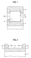
- Fig. 1 is an axial cross-sectional view of a roller bearing according to one embodiment of the invention.
- the roller bearing according to this embodiment of the invention comprises an inner ring 11 and an outer ring 12, as shown in Fig. 1.
- the outside diameter of the inner ring 11 is smaller than the inside diameter of the outer ring 12.
- the inner ring 11 is formed like an annulus ring.
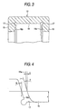
- a rolling contact surface 13 of rolling element is formed on an outer circumferential face of the inner ring 11, as shown in Fig. 2.
- the inside diameter of the outer ring 12 is larger than the outside diameter of the inner ring 11.
- the outer ring 12 is formed like an annulus ring.
- a rolling contact surface 14 of rolling element is formed on an inner circumferential face of the outer ring 12, as shown in Fig. 3. These rolling contact surfaces 13 and 14 of rolling elements are opposed to each other.
- a plurality of cylindrical rollers 15 as rolling elements are provided for free rolling between the rolling contact surface 13 of rolling element on the inner ring and the rolling contact surface 14 of rolling element on the outer ring.
- Each cylindrical roller 15 has two end faces 15a opposed to the inner side faces 16a of the flange portions 16 (see Figs. 2 and 3), which are formed at both end parts of the outer circumferential face of the inner ring 11 and both end parts of the inner circumferential face of the outer ring 12.
- the inner side face 16a of the flange portion 16 is an inclined surface inclined at a predetermined opening angle to the end face 15a of the cylindrical roller 15.
- reference numeral 17 is a grinding clearance groove formed at the base end part of the inner side face 16a of the flange portion.
- y a ⁇ exp (-b ⁇ x)
- ⁇ denotes an opening angle of the inner side face 16a of the flange portion
- 1 denotes a tangential line of a crowning curve
- ⁇ denotes a gradient of the tangential line 1 at a contact position between the cylindrical roller 15a and the flange portion 16.
- x, y and d are dimensionless quantities of the actual values divided by the roller diameter in this specification.
- Fig. 5 shows the relationship between the gradient ⁇ of tangential line 1 and the distance x.
- the relationship between the gradient ⁇ and the distance x when the peripheral part of end face of the cylindrical roller 15 is crowned at a single curvature is indicated by the broken line A.
- the distance x from the rolling contact surface or rolling element is less changed even if the gradient ⁇ of tangential line 1 is greatly changed when the peripheral part of end face of the cylindrical roller 15 is crowned in the curving shape as represented by expression (1) than when the peripheral part of end face of the cylindrical roller 15 is crowned at single curvature.
- Fig. 6 is a view showing a state where an end face of the cylindrical roller contacts an inner side face of the flange portion without skewing.
- d denotes an axial interval between the end face 15a of cylindrical roller and the inner side face 16a of flange portion when the end face 15a of cylindrical roller contacts an inner side face 16a of flange portion.
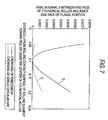
- Fig. 7 shows the relationship between the axial interval d and the distance x from the rolling contact surface of rolling element.
- the relationship between the axial interval d and the distance x when the peripheral part of end face of the cylindrical roller 15 is crowned at a single curvature is indicated by the broken line C.
- the axial interval d between the end face 15a of cylindrical roller and the inner side face 16a of the flange portion is more greatly changed with a change in the distance x when the peripheral part of end face of the cylindrical roller 15 is crowned in the curving shape as represented by expression (1) as compared with when the peripheral part of end face of the cylindrical roller 15 is crowned at a single curvature. That is, the axial interval d is sharply expanded slightly out of the position contact with the flange portion.
- the clearance (axial interval d) formed between the end face 15a of cylindrical roller and the inner side face 16a of flange portion is secured larger than conventionally, whereby a lubricant such as grease is likely to permeate between the end face 15a of cylindrical roller and the inner side face 16a of flange portion, preventing the occurrence of seizure and edge load.
- Figs. 8A and 8B are views showing a state where the cylindrical roller 15 is skewed.
- P1 denotes a first contact point distance from the rolling contact surface 14 of outer ring to the contact point between the cylindrical roller 15 and the flange portion 16
- P2 denotes a second contact point distance from the outer circumferential face of cylindrical roller to the contact point between the cylindrical roller 15 and the flange portion 16.
- ⁇ denotes a maximum skew angle of the cylindrical roller 15 that can occur geometrically.
- ⁇ L1 denotes the sum of axial intervals from the inner side face of flange portion to the base end part of flange portion at the contact height h
- ⁇ L2 denotes the sum of crowning fall-off amounts on the end face of cylindrical roller at the contact height h
- ⁇ S denotes the sum of axial intervals from the base end part of flange portion to the end face of cylindrical roller as shown in Fig.
- this skew angle ⁇ is represented by the following expression.
- ⁇ sin -1 2b 1 1 r (1+ ⁇ ) - ⁇ (2b 1 1 r ) 2 (1+ ⁇ ) 2 - 8 ⁇ 1 r 2 (1 r 2 +b 1 2 ) ⁇ 1 ⁇ 2 2 (1 r 2 +b 1 2 )
- ⁇ ( ⁇ L1+ ⁇ L2)/1 r + ⁇ s ( ⁇ 1)
- ⁇ s ⁇ S/1 r
- H0 denotes the height of a grinding clearance groove 17 at the base end of flange portion
- H1 denotes the height H of the flange portion 16 subtracted by a chamfer amount at the upper end of the flange portion.
- Fig. 10 shows the relationship between contact point distances P1, P2 and skew angle ⁇ and As.
- the relationship between the contact point distance P1 and the skew angle ⁇ and ⁇ s is indicated by the solid line E, supposing that the diameter of the cylindrical roller 15 is 24mm, the axial length 1 r of the cylindrical roller 15 is 26mm, the chamfer amount C of the cylindrical roller 15 is 1mm, the raceway diameter of outer ring is 180.5mm, and the opening angle ⁇ is 20 minutes.
- the relationship between the contact point distance P2 and the skew angle ⁇ and ⁇ s is indicated by the broken line F, supposing that the diameter of the cylindrical roller 15 is 24mm, the axial length 1 r of the cylindrical roller 15 is 26mm, the chamfer amount C of the cylindrical roller 15 is 1mm, the raceway diameter of outer ring is 180.5mm, and the opening angle ⁇ is 20 minutes.
- the range of ⁇ s is made a design range as shown in Fig. 10.
- H1 is 6mm in the above embodiments.
- the range of ⁇ s is made a design range as shown in Fig. 10 when H1 is 5mm. Even when the cylindrical roller 15 is skewed, the contact position between the cylindrical roller 15 andthe flange portion 16 is placed within the inner side face of the flange portion 16.
- the contact point distance P1 on the flange plane is increased to approach an upper end of the flange portion 16, as As is greater.
- the contact point distance P2 on the end face of roller is decreased to approach a rolling contact surface of roller, as ⁇ s is greater.
- the design area is the area where P1 does not exceed H1, and P2 is not smaller than the chamfer amount C of roller or H0.
- ⁇ s in which the line E is restricted to H1 is the upper limit of ⁇ s in the design area.
- the peripheral part of end face of the cylindrical roller is crowned in the curving shape represented by expression (1) .
- the roller bearing is prevented from an increased cost, seizure or edge load and a premature wear due to skew.
Landscapes
- Engineering & Computer Science (AREA)
- General Engineering & Computer Science (AREA)
- Mechanical Engineering (AREA)
- Rolling Contact Bearings (AREA)
Applications Claiming Priority (2)
| Application Number | Priority Date | Filing Date | Title |
|---|---|---|---|
| JP2003151317A JP2004353744A (ja) | 2003-05-28 | 2003-05-28 | ころ軸受 |
| JP2003151317 | 2003-05-28 |
Publications (2)
| Publication Number | Publication Date |
|---|---|
| EP1482191A2 true EP1482191A2 (fr) | 2004-12-01 |
| EP1482191A3 EP1482191A3 (fr) | 2007-04-04 |
Family
ID=33128257
Family Applications (1)
| Application Number | Title | Priority Date | Filing Date |
|---|---|---|---|
| EP20040012634 Withdrawn EP1482191A3 (fr) | 2003-05-28 | 2004-05-27 | Palier à contact de roulement |
Country Status (4)
| Country | Link |
|---|---|
| US (1) | US6997617B2 (fr) |
| EP (1) | EP1482191A3 (fr) |
| JP (1) | JP2004353744A (fr) |
| CN (1) | CN100360820C (fr) |
Cited By (3)
| Publication number | Priority date | Publication date | Assignee | Title |
|---|---|---|---|---|
| WO2007071228A1 (fr) * | 2005-12-21 | 2007-06-28 | Schaeffler Kg | Palier a roulement |
| EP2202418A1 (fr) * | 2008-12-24 | 2010-06-30 | Jtekt Corporation | Roulement |
| DE102010062481B3 (de) * | 2010-12-06 | 2011-12-15 | Aktiebolaget Skf | Geometriekonzept für einen Rolle-Bord-Kontakt bei Rollenlagern |
Families Citing this family (16)
| Publication number | Priority date | Publication date | Assignee | Title |
|---|---|---|---|---|
| US7371179B2 (en) * | 2005-06-23 | 2008-05-13 | Honda Motor Co., Ltd. | Tripod constant-velocity universal joint |
| CN101305165B (zh) * | 2005-11-03 | 2010-11-10 | 沃尔沃拉斯特瓦格纳公司 | 冠状轮廓 |
| DE102005061179A1 (de) * | 2005-12-21 | 2007-06-28 | Schaeffler Kg | Wälzlager und Verfahren zu dessen Herstellung |
| JP2007309508A (ja) * | 2006-04-20 | 2007-11-29 | Kinyosha Co Ltd | 揺動ローラー、転がり軸受、ローラーの揺動方法 |
| JP4980031B2 (ja) * | 2006-11-10 | 2012-07-18 | Ntn株式会社 | ころ軸受のクラウニングの設計方法 |
| EP2080919B1 (fr) | 2006-11-10 | 2019-01-16 | NTN Corporation | Procédé de fabrication de roulement à rouleaux |
| DE102008028164B4 (de) * | 2008-06-12 | 2021-07-01 | Ab Skf | Rolle und Rollenlager mit der Rolle |
| JP5455329B2 (ja) * | 2008-06-24 | 2014-03-26 | Ntn株式会社 | 円筒ころ軸受 |
| DE102010018553A1 (de) * | 2010-04-28 | 2012-01-19 | Aktiebolaget Skf | Rolle und Rollenlager |
| CN102261383A (zh) * | 2011-04-27 | 2011-11-30 | 洛阳轴研科技股份有限公司 | 一种混合陶瓷圆柱滚子轴承套圈 |
| JP2013117249A (ja) * | 2011-12-02 | 2013-06-13 | Ntn Corp | ころ軸受 |
| CN103511450B (zh) * | 2013-06-17 | 2016-06-29 | 慕建国 | 角接触滚柱轴承 |
| CN105992882A (zh) | 2013-11-21 | 2016-10-05 | 日本精工株式会社 | 圆筒滚子轴承和变速器用轴承装置 |
| US20170210166A1 (en) | 2014-09-11 | 2017-07-27 | Koyo Bearings North America Llc | Axle wheel end axial thrust assembly |
| US11053978B2 (en) | 2017-04-26 | 2021-07-06 | The Timken Company | Non-elliptical contact profile for roller bearing |
| DE102020211036B4 (de) * | 2020-09-02 | 2022-04-14 | Aktiebolaget Skf | Anordnung mit einem Schleifwerkzeug und einer Rolle für ein Rollenlager sowie Verfahren zum Herstellen einer Rolle für ein Rollenlager |
Citations (2)
| Publication number | Priority date | Publication date | Assignee | Title |
|---|---|---|---|---|
| JPH0712119A (ja) | 1993-06-28 | 1995-01-17 | Nippon Seiko Kk | 円筒ころ軸受 |
| JP2002070874A (ja) | 2000-08-28 | 2002-03-08 | Nsk Ltd | 回転支持装置 |
Family Cites Families (6)
| Publication number | Priority date | Publication date | Assignee | Title |
|---|---|---|---|---|
| JPS5436990Y2 (fr) | 1975-06-09 | 1979-11-07 | ||
| JPS5913369Y2 (ja) | 1979-07-18 | 1984-04-20 | 日本精工株式会社 | 円筒ころ軸受 |
| JPH0712133A (ja) | 1993-06-28 | 1995-01-17 | Nippon Seiko Kk | 円筒ころ軸受 |
| JPH10196660A (ja) | 1996-11-13 | 1998-07-31 | Nippon Seiko Kk | ころ軸受 |
| JP3731401B2 (ja) * | 1999-08-31 | 2006-01-05 | 日本精工株式会社 | ころ軸受 |
| JP2003021145A (ja) * | 2001-07-05 | 2003-01-24 | Nsk Ltd | ころ軸受 |
-
2003
- 2003-05-28 JP JP2003151317A patent/JP2004353744A/ja active Pending
-
2004
- 2004-05-27 EP EP20040012634 patent/EP1482191A3/fr not_active Withdrawn
- 2004-05-27 US US10/854,262 patent/US6997617B2/en not_active Expired - Fee Related
- 2004-05-28 CN CNB2004100631556A patent/CN100360820C/zh not_active Expired - Fee Related
Patent Citations (2)
| Publication number | Priority date | Publication date | Assignee | Title |
|---|---|---|---|---|
| JPH0712119A (ja) | 1993-06-28 | 1995-01-17 | Nippon Seiko Kk | 円筒ころ軸受 |
| JP2002070874A (ja) | 2000-08-28 | 2002-03-08 | Nsk Ltd | 回転支持装置 |
Cited By (6)
| Publication number | Priority date | Publication date | Assignee | Title |
|---|---|---|---|---|
| WO2007071228A1 (fr) * | 2005-12-21 | 2007-06-28 | Schaeffler Kg | Palier a roulement |
| US8469599B2 (en) | 2005-12-21 | 2013-06-25 | Schaeffler Technologies AG & Co. KG | Rolling bearing |
| EP2202418A1 (fr) * | 2008-12-24 | 2010-06-30 | Jtekt Corporation | Roulement |
| US8317405B2 (en) | 2008-12-24 | 2012-11-27 | Jtekt Corporation | Rolling bearing |
| DE102010062481B3 (de) * | 2010-12-06 | 2011-12-15 | Aktiebolaget Skf | Geometriekonzept für einen Rolle-Bord-Kontakt bei Rollenlagern |
| US8899839B2 (en) | 2010-12-06 | 2014-12-02 | Aktiebolaget Skf | Geometric concept for a roller-flange contact in roller bearings |
Also Published As
| Publication number | Publication date |
|---|---|
| JP2004353744A (ja) | 2004-12-16 |
| EP1482191A3 (fr) | 2007-04-04 |
| US6997617B2 (en) | 2006-02-14 |
| CN1573145A (zh) | 2005-02-02 |
| CN100360820C (zh) | 2008-01-09 |
| US20040240764A1 (en) | 2004-12-02 |
Similar Documents
| Publication | Publication Date | Title |
|---|---|---|
| US6997617B2 (en) | Roller bearing | |
| US5626426A (en) | Self-aligning roller bearing with retainer | |
| US5501530A (en) | Double-row ball bearing of angular type for wheel | |
| US5456538A (en) | Roller bearing | |
| US20110116734A1 (en) | Punched retainer, self-aligning roller bearing, and method of manufacturing punched retainer | |
| EP0381336A1 (fr) | Palier en céramique | |
| WO2013140948A1 (fr) | Dispositif de retenue pour un roulement à rouleaux, et structure de roulement à rouleaux | |
| JPH0828576A (ja) | 保持器付自動調心ころ軸受 | |
| US9011018B2 (en) | Roller bearing | |
| EP1816362A1 (fr) | Roulement a rotule sur rouleaux muni d'un dispositif de retenue et procede de fabrication du dispositif de retenue pour le roulement a rotule sur rouleaux | |
| JP3562587B2 (ja) | ころ軸受 | |
| EP2239473B1 (fr) | Cage de roulement | |
| US10948012B2 (en) | Thrust roller bearing | |
| US6206576B1 (en) | Cage for cylindrical rolling elements | |
| JP2000320558A (ja) | ころ軸受用合成樹脂製保持器 | |
| JP2011094716A (ja) | スラストころ軸受 | |
| EP1069327B1 (fr) | Cage de roulement pour palier, et palier à contact de roulement utilsant une telle cage | |
| US12209615B2 (en) | Anti-rotation snap ring to prevent bearing creep | |
| CN108884865B (zh) | 多列圆筒滚子轴承 | |
| JP2003130058A (ja) | 転がり機械要素 | |
| WO2023063043A1 (fr) | Roulement à rouleaux cylindriques | |
| US7168859B2 (en) | Thrust ball bearing | |
| JPH1089364A (ja) | 固体潤滑クロスロ−ラ軸受 | |
| JP4457601B2 (ja) | シェル型ニードル軸受 | |
| JP2002155955A (ja) | 鍔付円筒ころ軸受 |
Legal Events
| Date | Code | Title | Description |
|---|---|---|---|
| PUAI | Public reference made under article 153(3) epc to a published international application that has entered the european phase |
Free format text: ORIGINAL CODE: 0009012 |
|
| AK | Designated contracting states |
Kind code of ref document: A2 Designated state(s): AT BE BG CH CY CZ DE DK EE ES FI FR GB GR HU IE IT LI LU MC NL PL PT RO SE SI SK TR |
|
| AX | Request for extension of the european patent |
Extension state: AL HR LT LV MK |
|
| PUAL | Search report despatched |
Free format text: ORIGINAL CODE: 0009013 |
|
| AK | Designated contracting states |
Kind code of ref document: A3 Designated state(s): AT BE BG CH CY CZ DE DK EE ES FI FR GB GR HU IE IT LI LU MC NL PL PT RO SE SI SK TR |
|
| AX | Request for extension of the european patent |
Extension state: AL HR LT LV MK |
|
| RIC1 | Information provided on ipc code assigned before grant |
Ipc: F16C 33/58 20060101ALI20070228BHEP Ipc: F16C 33/36 20060101AFI20070228BHEP |
|
| 17P | Request for examination filed |
Effective date: 20070525 |
|
| AKX | Designation fees paid |
Designated state(s): DE |
|
| 17Q | First examination report despatched |
Effective date: 20090909 |
|
| STAA | Information on the status of an ep patent application or granted ep patent |
Free format text: STATUS: THE APPLICATION IS DEEMED TO BE WITHDRAWN |
|
| 18D | Application deemed to be withdrawn |
Effective date: 20100120 |