EP1486191A1 - Bewegliches bett - Google Patents
Bewegliches bett Download PDFInfo
- Publication number
- EP1486191A1 EP1486191A1 EP03705137A EP03705137A EP1486191A1 EP 1486191 A1 EP1486191 A1 EP 1486191A1 EP 03705137 A EP03705137 A EP 03705137A EP 03705137 A EP03705137 A EP 03705137A EP 1486191 A1 EP1486191 A1 EP 1486191A1
- Authority
- EP
- European Patent Office
- Prior art keywords
- platform
- bed
- tilt
- flex
- adjustable
- Prior art date
- Legal status (The legal status is an assumption and is not a legal conclusion. Google has not performed a legal analysis and makes no representation as to the accuracy of the status listed.)
- Withdrawn
Links
Images












Classifications
-
- A—HUMAN NECESSITIES
- A61—MEDICAL OR VETERINARY SCIENCE; HYGIENE
- A61G—TRANSPORT, PERSONAL CONVEYANCES, OR ACCOMMODATION SPECIALLY ADAPTED FOR PATIENTS OR DISABLED PERSONS; OPERATING TABLES OR CHAIRS; CHAIRS FOR DENTISTRY; FUNERAL DEVICES
- A61G7/00—Beds specially adapted for nursing; Devices for lifting patients or disabled persons
- A61G7/002—Beds specially adapted for nursing; Devices for lifting patients or disabled persons having adjustable mattress frame
- A61G7/008—Beds specially adapted for nursing; Devices for lifting patients or disabled persons having adjustable mattress frame tiltable around longitudinal axis, e.g. for rolling
-
- A—HUMAN NECESSITIES
- A61—MEDICAL OR VETERINARY SCIENCE; HYGIENE
- A61G—TRANSPORT, PERSONAL CONVEYANCES, OR ACCOMMODATION SPECIALLY ADAPTED FOR PATIENTS OR DISABLED PERSONS; OPERATING TABLES OR CHAIRS; CHAIRS FOR DENTISTRY; FUNERAL DEVICES
- A61G7/00—Beds specially adapted for nursing; Devices for lifting patients or disabled persons
- A61G7/001—Beds specially adapted for nursing; Devices for lifting patients or disabled persons with means for turning-over the patient
-
- A—HUMAN NECESSITIES
- A61—MEDICAL OR VETERINARY SCIENCE; HYGIENE
- A61G—TRANSPORT, PERSONAL CONVEYANCES, OR ACCOMMODATION SPECIALLY ADAPTED FOR PATIENTS OR DISABLED PERSONS; OPERATING TABLES OR CHAIRS; CHAIRS FOR DENTISTRY; FUNERAL DEVICES
- A61G7/00—Beds specially adapted for nursing; Devices for lifting patients or disabled persons
- A61G7/002—Beds specially adapted for nursing; Devices for lifting patients or disabled persons having adjustable mattress frame
- A61G7/015—Beds specially adapted for nursing; Devices for lifting patients or disabled persons having adjustable mattress frame divided into different adjustable sections, e.g. for Gatch position
-
- A—HUMAN NECESSITIES
- A61—MEDICAL OR VETERINARY SCIENCE; HYGIENE
- A61G—TRANSPORT, PERSONAL CONVEYANCES, OR ACCOMMODATION SPECIALLY ADAPTED FOR PATIENTS OR DISABLED PERSONS; OPERATING TABLES OR CHAIRS; CHAIRS FOR DENTISTRY; FUNERAL DEVICES
- A61G2203/00—General characteristics of devices
- A61G2203/30—General characteristics of devices characterised by sensor means
- A61G2203/42—General characteristics of devices characterised by sensor means for inclination
-
- A—HUMAN NECESSITIES
- A61—MEDICAL OR VETERINARY SCIENCE; HYGIENE
- A61G—TRANSPORT, PERSONAL CONVEYANCES, OR ACCOMMODATION SPECIALLY ADAPTED FOR PATIENTS OR DISABLED PERSONS; OPERATING TABLES OR CHAIRS; CHAIRS FOR DENTISTRY; FUNERAL DEVICES
- A61G7/00—Beds specially adapted for nursing; Devices for lifting patients or disabled persons
- A61G7/05—Parts, details or accessories of beds
- A61G7/057—Arrangements for preventing bed-sores or for supporting patients with burns, e.g. mattresses specially adapted therefor
- A61G7/05769—Arrangements for preventing bed-sores or for supporting patients with burns, e.g. mattresses specially adapted therefor with inflatable chambers
-
- Y—GENERAL TAGGING OF NEW TECHNOLOGICAL DEVELOPMENTS; GENERAL TAGGING OF CROSS-SECTIONAL TECHNOLOGIES SPANNING OVER SEVERAL SECTIONS OF THE IPC; TECHNICAL SUBJECTS COVERED BY FORMER USPC CROSS-REFERENCE ART COLLECTIONS [XRACs] AND DIGESTS
- Y10—TECHNICAL SUBJECTS COVERED BY FORMER USPC
- Y10S—TECHNICAL SUBJECTS COVERED BY FORMER USPC CROSS-REFERENCE ART COLLECTIONS [XRACs] AND DIGESTS
- Y10S5/00—Beds
- Y10S5/942—Longitudinally divided top surface with pivotable section
Definitions
- the present invention relates to adjustable beds for use in nursing care and the like, and particularly to improving the mechanism for turning users of the bed, such as care recipients, between supine and lateral positions.
- adjustable beds used as turning beds and the like to assist the postural change of care recipients in order to prevent the occurrence of decubitus ulcers, more commonly known as bedsores
- the person is turned by tilting at least part of the mattress on which the person is lying at an angle (see Japanese Published Patent Publication No. 6-14824).
- the majority of these types of beds employ a mechanism that tilts the mattress toward one side or the other from a horizontal position.
- the posture of the care recipient is changed from a position lying flat on a horizontal mattress (i.e. supine) to a lateral position in which the person is lying on either their left or right side (i.e. lateral).
- the most stable posture for a person turning laterally is a flexion position with knees bent and hips flexed.
- the caregiver when moving the care recipient from a supine to a lateral position, preferably adjusts the person's posture to be suitably placed in a flexion position.
- the present invention aims to provide an adjustable bed capable of facilitating postural changes, while minimizing any physical discomfort or psychological anxiety caused to a care recipient using the bed.
- an adjustable bed that includes a platform having a flexible surface; a flex mechanism adapted to flex the platform to form a flexion position that includes at least one of a sitting-up position and a knee break; and a tilt mechanism adapted to tilt the platform surface laterally, the flex and tilt mechanisms both being operable with the other mechanism in an operational state.
- the care recipient Since the care recipient, according to this structure, is able to achieve postural changes to a flexion position and from a supine to a lateral position using the turning bed, positional changes from a supine to a lateral position and vice versa are performed excellently by operations that are just like those carried out by the guiding hand of a caregiver.
- this invention enables the care recipient to achieve postural changes while in a flexion position, which exerts the least burden on the care recipient's body, it is possible for the care recipient to look forward to an easing of the physical discomfort and psychological anxiety experienced to date.
- the care recipient is thus able to comfortably face postural changes, and the occurrence of decubitus ulcers can be effectively suppressed.
- the caregiver when the present invention is used, is not required to perform overly exerting manual tasks when changing the posture of the care recipient, it is possible for even a caregiver with little experience to correctly perform postural changes.
- the caregiver having had their burden reduced, is thus better able to focus on providing the best care possible.
- the adjustable bed may include a side member disposed on a side of the platform; and a side-member lift mechanism adapted to raise the side member relative to the platform surface, and the tilt mechanism may tilt the platform surface toward the side member raised by the side-member lift mechanism. This enables the care recipient to be safely supported on the sides by the side member when postural changes are performed.
- the present invention may, specifically, be realized by the adjustable bed including a side member disposed on either side of the platform, the tilt mechanism including an elevation mechanism adapted to elevate the pair of side members up and down, and the platform surface being tilted and the side member at a lower end thereof being raised relative to the platform surface by elevating at least one side of the platform surface using the elevation mechanism.
- the platform may be formed from a plurality of surface members supported from underneath by an adjustable stage that oscillates on a fixed stage
- the flex mechanism may have an actuator disposed on an underside of the platform and adapted to flex the platform by tilting one or more of the surface members
- the tilt mechanism may have a first and a second elevation mechanism capable of elevating both sides of the adjustable stage independently
- the flex and tilt mechanisms may be independently operable.
- elevation mechanisms capable of independent elevation as described above, and operating these elevation mechanisms in sync in addition to tilting the platform, it is possible to elevate (raise/lower) the platform (i.e. to operate a high/low mechanism).
- the platform may be a coupled platform formed from the surface members being coupled together
- the flex mechanism may drive the actuator, which is disposed on the underside of the coupled platform, to flex the coupled platform
- the first and second elevation mechanisms may each include a parallelogram mechanism adapted to elevate sides of the adjustable stage in a perpendicular direction using (i) a plurality of support arms that hang down parallel with one another from the respective side of the adjustable stage so as to extend in line with the side, (ii) a horizontal link arm disposed with respect to the support arms so as to extend in line with a flat surface of the bed, and (iii) a slide groove member disposed horizontally and connected to a lower end of the support arms so as to allow the support arms to travel freely, and the platform surface may be tilted by separating one side of the adjustable stage and the respective horizontal link arm using another actuator, to lift the side.
- the side members may each be formed from (i) a first side member having a slot in a thickness direction, and (ii) a second side member housed in the slot and coupled to the first side member and the platform, and the tilt mechanism may be structured such that the second side member is pulled from the slot in the first side member when the platform surface is tilted. Substantially the same effects as those described above are also achieved by this configuration.
- an adjustable bed that achieves the above object may be structured to include a plurality of airbags laid along a bed surface; a sidewall lift mechanism adapted to inflate airbags provided on side parts of the bed surface, to form a pair of sidewalls; a flex mechanism adapted to form a flexion position that includes at least one of a sitting-up position and a knee break, by inflating or deflating an airbag provided on a middle part of the bed surface; and a tilt mechanism adapted to inflate or deflate airbags provided on the middle and side parts after the sidewall lift mechanism is operated, so as to tilt the bed surface of the middle part toward one of the sidewalls, the flex and tilt mechanisms both being operable with the other mechanism in an operational state. Substantially the same effects as those described above are also achieved by this configuration.
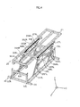
- Fig.1 is a perspective view showing a structure of a turning bed 1 relating to an embodiment 1 of the present invention.
- Turning bed 1 is constituted such that a bed frame 10 is disposed on an adjustable stage 20 sitting on a fixed stage 3.0.
- Bed frame 10 includes coupled platforms 11a to 11d, which are formed by dividing a surface section (i.e. upper surface of the bed) into four articular sections corresponding to the back, hip, upper leg, and lower leg regions of the care recipient's body when lying on the bed, and coupling these sections together so as to be fully adjustable.
- lower-back board 11b is fixed directly to adjustable stage 20 by being welded, for example, thus preventing bed frame 10 from separating from adjustable stage 20.
- Side members 12Ra-12Rd and 12La-12Ld for supporting the care recipient's body from the side are coupled to platforms 11a-11d on the right and left, respectively.
- Coupled platforms 11a-11d and side members 12Ra-12Rd/12La-12Ld of bed frame 10 are in actual fact covered by wire mesh, although in order to clearly depict the bed's structure, this wire mesh has been omitted from the drawings, which consequently depict only the frames of platforms 11a-11d and side members 12Ra-12Rd/12La-12Ld.
- the platforms and side members are not restricted to having a wire mesh surface construction, and may alternatively be formed from coupled pieces of a sheet material.
- certain parts of the structure such as side-member support frames 24R/24L, for example, have been omitted so as to clearly illustrate the operations.
- Adjustable stage 20 has a rectangular frame construction formed from center frame part 21A, side frame parts 21R/21L, and two parallel end frame parts connected to either end of the center and side frame parts.
- Rollers 200, 201, 202 and 203 (roller 203 hidden beneath bed frame 10 in Fig.1) are disposed on side frame parts 21R/21L, and are able to slide in a y direction along the top of roller-track frame parts 300 and 301 of fixed stage 30, as shown in Fig.1.
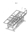
- Ladder-shaped side-member support frames 24R/24L are disposed on side frame parts 21R/21L of adjustable stage 20, and formed respectively from two bars 22R/23R and 22L/23L that run along side frame parts 21R/21L, and two couplers 231R/232R and 231L/232L. Bars 23R/23L bend outwards in an area where side-member support frames 24R/24L correspond to side members 12Rb/12Lb, with side members 12Rb/12Lb lying within the space provided by the outwardly bent section (see Fig.3 plan view of bed).
- Side members 12Rb/12Lb and side members 12Ra/12La and 12Rc/12Lc on either side of 12Rb/12Lb are designed so as not to interfere with one another in a width direction when bed frame 10 changes to the flexion position.
- Bars 22R/22L are coupled respectively to bars 23R/23L by couplers 231R/232R and 231L/232L, allowing bars 22R/22L to rotate freely in an axial direction while remaining secured to side frame parts 21R/21L of adjustable stage 20.
- side-member support frames 24R/24L are rotated on the axis of rotating bars 22R/22L to a position perpendicular with the horizontal bed (i.e. so as to point in the z direction)
- side members 12Ra-12Rd/12La-12Ld of bed frame 10 are pushed up, enabling the right and left sides of bed frame 10 to be raised.
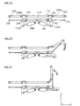
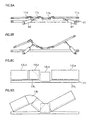
- Figs. 2A to 2C are schematic sectional views of the bed showing the operation of actuators in a vicinity of adjustable stage 20 and lower-back board 11c of bed frame 10.
- direct-acting actuators M3R/M3L are, as shown in Figs.2A-2C, disposed symmetrically on adjustable stage 20 so as to extend respectively to the left and right of center frame part 21A (i.e. in the y direction toward coupling members 236Ra/236La, respectively), the head of the axial parts of actuators M3R/M3L being coupled to L-shaped members 235R/235L fixed below rotating bars 22R/22L.
- L-shaped members 235R/235L and bars 23R/23L are rotated on the axis of rotating bars 22R/22L due to the axial parts of actuators M3R/M3L being extended, which raises side-member support frames 24R/24L from the horizontal to a position perpendicular with the horizontal (Figs. 2A ⁇ 2B ⁇ 2C).
- Stage bars 27R/27L are provided on the underside of side frame parts 21R/21L, and mate with stage-bar receivers 36R/36L (U-shaped cross-section) on, fixed stage 30.
- Stage-bar receivers 36R/36L each have a reverse L-shaped claw that runs internally in a width direction, adjustable stage 20 being secured in a vertical direction by these claws hooking around stage bars 27R/27L.
- Adjustable stage 20 and fixed stage 30 can also be coupled together using the following mechanism.
- pole-shaped members that extend in a longitudinal direction of the bed may be provided on the underside of side frame parts 32R/32L on fixed stage 30, and an engaging mechanism provided with respect to the swing bars that is capable of being locked/unlocked automatically when the bed is operated.
- the swing bars are structured to mate with grips provided on fixed stage 30.
- the swing bars mate with the grips when side members 12Ra-12Rd/12La-12Ld are horizontal, locking the engaging mechanism. Raising the swing bar on one side when the bed is operated raises the side members on the corresponding side (i.e. 12Ra-12Rd or 12La-12Ld). This unlocks the engaging mechanism on the side that is raised, allowing adjustable stage 20 to be tilted.
- adjustable stage 20 Since this mechanism enables adjustable stage 20 to remain securely coupled to fixed stage 30 when the bed is normally positioned (horizontal), and to be separated from fixed stage 30 only when necessary, operational safety is improved.
- Fig. 4 is a perspective view showing a structure of fixed stage 30.
- Fixed stage 30 includes a rectangular frame 31.
- the opposing ends of frame 31 form roller-track frame parts 300 and 301, with rollers 200-203 of adjustable stage 20 being able to travel back and forth along the tops of frame parts 300 and 301.
- the ends of support arms 354R/356R and 354L/356L coupled respectively to stage-bar receivers 36R/36L are fitted into side frame parts 32R/32L so as to have free travel.
- Reverse L-shaped rotating arms 351R/352R and 351L/352L coupled at one end to side frame parts 32R/32L are linked to support arms 354R/356R and 354L/356L, and horizontal links 353R and 353L are coupled to rotating arms 351R/352R and 351L/352L.
- Actuators M4R/M4L are disposed at an angle between stage-bar receivers 36R/36L and horizontal links 353R/353L, respectively.
- Parallelogram mechanisms 35R/35L applies as horizontal slide mechanisms are thus formed on the right and left sides of fixed stage 30.
- rotating arms 351R/352R and 351L/352L move in a circular motion around the points at which they are coupled to side frame parts 32R/32L, and support arms 354R/356R and 354L/356L travel back and forth at one end on the inside of side frame parts 32R and 32L, while being regulated by rotating arms 351R/352R and 351L/352L.
- Oscillating support arms 354R/356R and 354L/356L enable adjustable stage 20, supported by stage-bar receivers 36R/36L, and bed frame 10 to be elevated vertically from both the right and left sides of fixed stage 30.
- turning bed 1 can be elevated even in the narrow spaces that result from space saving, while the use of rollers 200-203 and parallelogram mechanisms 35R and 35L enables space to be saved even during postural change operations.
- Postural changes from a supine to a lateral position are achieved when one of parallelogram mechanisms 35R/35L corresponding respectively to side frame parts 32R/32L is driven, while a high/low (height adjustment) mechanism of the bed is realized when parallelogram mechanisms 35R/35L are driven simultaneously.
- Actuators M1/M2 and M3R/M3L are controlled by a CPU 601 and a motor driver 603 in a control unit 600, the caregiver being able to carry out drive settings (e. g. manual/automatic, program settings, etc) using a controller (not depicted). Also, the provision of a cable (cord attached, etc) or wireless (infrared, etc) remote controller enables settings to also be performed by the care recipient.
- a turning bed having the above structure is used with a mattress placed on bed frame 10.
- coupled platforms 11a-11d and side members 12Ra-12Rd/12La-12Ld are set, as shown in Fig.1, to be substantially horizontal.
- actuator M3L attached to adjustable stage 20 is firstly operated, the axial part of actuator M3L extending outward.
- L-shaped member 235L coupled to the end of the axial part and bar 23L rotate around rotating bar 22L, and side-member support frame 24L rise from a horizontal position toward a position vertical with the flat surface of the bed (see Figs . 2A ⁇ 2B ⁇ 2C showing actuator operations; Fig.5 showing side members 12La-12Ld in a raised state; Fig.8C showing side view of bed in this state).
- the tilt angle (i.e. angle of inclination) of the upper leg when in the flexion position preferably is set in a range of 10 degrees to 60 degrees inclusive, since this effectively prevents the care recipient from rolling in the direction of the incline.
- a tilt angle in a range of 20 degrees to 40 degrees inclusive is more preferable.
- actuator M4R on the right side of fixed stage 30 operates and the axial part of the actuator extends outward.
- stage-bar receiver 36R and horizontal link 353R separate from one another at an angle, support arms 354R and 356R slide along the slide channel in side frame part 32R and rise up, and parallelogram mechanism 35R operates.
- Support arms 354R and 356R (or 354L, 356L) thus raise one side of the adjustable stage vertically upwards as a result of the circular movement of rotating arms 351R and 352R (or 351L, 352L).
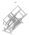
- adjustable stage 20 is raised to a higher position than fixed stage 30, rollers 200-203 of adjustable stage 20 roll along the top of roller-track frame parts 300 and 301, and bed frame 10 tilts toward side frame part 32L of fixed stage 30; that is, toward the left side of the bed (see Fig. 7 perspective view of bed when tilted).
- a tilt angle in a range, for example, of approximately 30 degrees to 70 degrees inclusive is preferable, one example being a tilt angle of 50 degrees.
- embodiment 1 allows postural changes to be performed while in a flexion position, which exerts the least burden on the care recipient's body, the care recipient is able to comfortably face postural changes, and can look forward to an easing of the physical discomfort and psychological anxiety associated with postural changes to date.
- the caregiver since the caregiver is not required to perform overly exerting manual tasks when changing the posture of the care recipient, it is possible for even a caregiver with little experience to correctly perform postural changes.
- the caregiver is thus better able to focus on providing the best care possible.
- the care recipient is firstly placed in a Gatch position (i.e. semi-recumbent with knees elevated to prevent the care recipient from sliding toward the foot of the bed) after raising one set of side members (i.e. 12Ra-12Rd or 12La-12Ld), and then shifted from a supine to a lateral position.
- a Gatch position i.e. semi-recumbent with knees elevated to prevent the care recipient from sliding toward the foot of the bed
- one set of side members i.e. 12Ra-12Rd or 12La-12Ld
- the present invention is not limited to this configuration.
- a drive sequence may be employed in which the Gatch position is firstly obtained, as shown in Fig. 9, after which one set of side members is raised (see Fig. 10, for example), and then posture changed from a supine to a lateral position.
- the care recipient may feel tightly constrained by the raised set of side members (i.e. 12Ra-12Rd or 12La-12Ld). Such feelings can be alleviated by performing a control to slightly release the raised set of side members after the postural change is completed.
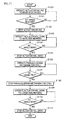
- Fig.11 is an exemplary flowchart relating to a side-member release control for alleviating the feeling of being constrained.
- actuators M1 and M2 are firstly operated in order to obtain the Gatch position with back and knees raised (step 100), actuators M1 and M2 being operated continuously until a predetermined angle is reached (step 101). Then, after stopping actuators M1 and M2 (step 102), actuator M3R or M3L is operated in order to elevate side members 12Ra-12Rd or 12La-12Ld (step 103), actuator M3R or M3L being operated continuously until side members 12Ra-12Rd or 12La-12Ld are angled at 90 degrees (step 104).
- actuator M3R or M3L parallelogram mechanism 35R or 35L is operated in order to tilt adjustable stage 20 (step 106), this being continued until adjustable stage 20 is tilted at a 50-degree angle (step 107), the drive being stopped at this exemplary tilt angle of 50 degrees (step 108).
- actuator M3R or M3L is operated so as to release whichever of side members 12Ra-12Rd or 12La-12Ld are bearing the weight of the care recipient (step 109), the tilt of side members 12Ra-12Rd or 12La-12Ld being returned from an angle of 90 degrees to 70 degrees (step 110).
- the angle here is not limited to 70 degrees, and may be any angle capable of supporting the care recipient's body.
- the operation of actuator M3R or M3L is stopped when an appropriate angle is achieved, and the release control ended.
- the description here relates to an exemplary operation sequence for operating the side members and parallelogram mechanisms in synchronization. Since the sync control sequence enables the above two separate operations to be performed at the same time, it is possible, in addition to achieving time reductions, to shift the care recipient's weight smoothly from the coupled platforms to the side members, and thus to reduce any psychological burden on the care recipient that accompanies postural changes.
- Fig.12 is a flowchart relating to this sync control sequence.
- actuators M1 and M2 are firstly operated so as to obtain the Gatch position (step 120), actuators M1 and M2 being operated continuously until a predetermined angle is reached (step 121). Then, after stopping actuators M1 and M2 (step 122), CPU 601 calculates the rotation speed of side members 12Ra-12Rd or 12La-12Ld relative to a horizontal direction, from a roll setting (i.e. adjustable stage 20 tilt angle, parallelogram mechanism 35R/35L operation speed) when parallelogram mechanism 35R or 35L is operated (step 123).
- a roll setting i.e. adjustable stage 20 tilt angle, parallelogram mechanism 35R/35L operation speed
- CPU 601 calculates the rate of change of the tilt angle of adjustable stage 20 and the rate of change of the tilt angle of side members 12Ra-12Rd or 12La-12Ld relative to platforms 11a-11d. Based on the calculated rates of change, actuator M3R or M3L is then operated so as to elevate side members 12Ra-12Rd or 12La-12Ld (step 124), and parallelogram mechanism 35R or 35L is operated at the same time (step 127). When the angles of side members 12Ra-12Rd (or 12La-12Ld) and parallelogram mechanism 35R (or 35L) reach 70 degrees and 50 degrees, respectively, while performing this sync driving, actuator M3R (or M3L) and parallelogram mechanism 35R (or 35L) are stopped and the sync control ended.
- the description here relates a number of embodiments for enabling a turning bed of the present invention to be used safely.
- Fig.13 is a sectional view of the turning bed.
- support arms (L-shaped cross-section) supported by fixed stage 30 are provided below bars 23R/23L
- load sensors S1 and S2 consisting of a micro switch are disposed on sections of the support arms facing bars 23R/23L.
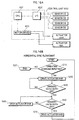
- the state of load sensors S1 and S2 (transmit detection signals showing respective ON/OFF states) are, as shown in the Fig.14A block diagram, managed by CPU 601 via an input/output (I/O) circuit 602 in control unit 600.
- I/O input/output
- CPU 601 When load sensors S1 and S2 are turned ON via bars 23R and 23L by the placement of a load on side members 12Rb/12Lb (i.e. when the care recipient's body is positioned over side members 12Rb/12Lb), CPU 601, as a safety measure, instructs motor driver 603 to stop the driving of actuators M1 and M2, and holds the turning operation in an OFF state.
- bars 23R/23L may be replaced members having flexible, springy properties.
- Fig.14B is a flowchart of a specific control relating to the above safety mechanism.
- CPU 601 firstly judges whether a command relating to a postural change operation has been inputted (i.e. bed has been turned ON) from the controller (step 1). If the bed has been turned ON, CPU 601 then judges at step 3 whether the detection signal from load sensors S1 and S2 both show the sensors to be OFF (i.e. judgment as to whether a load is placed over side members 12Rb and 12Lb). If the sensors are OFF, CPU 601 instructs motor driver 603 to drive the motors of actuators M1 and M2 (step 4), and the motors of actuators M1 and M2 are driven based on this instruction (step 5).
- sensors other than micro switches may be applied in the load sensors, an example of which is a device using a piezoelectric element.
- CPU 601 is described in the above example as controlling motor driver 603 to stop the driving of actuators M1 and M2, the present invention is not limited to this configuration.
- the present invention may be structured so that the turning operations are turned OFF using circuitry when load sensors S1 and S2 are OFF.
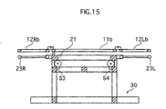
- Fig. 15 is a sectional view of the turning bed.
- load sensors S3, S4, S5 and S6 consisting of micro switches are disposed between rollers 200-203 of adjustable stage 20 and roller track frames 300 of fixed stage 30.
- Detection signals (ON/OFF) of load sensors S3-S6 are, as shown in the Fig.16A block diagram, managed by CPU 601 via I/O circuit 602 in control unit 600.
- load sensors S3-S6 are ON when in contact with adjustable stage 20, and turned OFF when adjustable stage 20 is elevated during the drive of the bed. Load sensors S3-S6 are provided for the following reason.
- actuators M4R/M4L and the like being provided in parallelogram mechanisms 35R/35L implemented in the turning bed of embodiment 1, operational errors may exist in these actuators due to precision variations during manufacture. Mechanical errors may also exist in parallelogram mechanisms 35R and 35L themselves, including the possibility of an operational delay in one of the actuators when operating parallelogram mechanisms 35R/35L in sync to elevate platforms 11a-11d in a horizontal position, or the coupled platforms being tilted at an angle due to the operation of parallelogram mechanisms 35R/35L not been smooth. This may cause psychological anxiety to a user lying on the bed.
- Load sensors S3-S6 are provided to suppress the occurrence of such problems.
- the following operations, for example, are possible according to this structure.
- CPU 601 when the turning bed is driven, CPU 601 firstly judges at step 10 whether a postural change operation command ("Raise Bed” operation) has been inputted from the controller (i.e. bed has been turned ON). If the bed has been turned ON, CPU 601 drives actuator M4R (step 30). Note that actuator M4L is also driven at this time. Then, if the detection signals from load sensors S3 and S5 mounted on same side of the bed as actuator M4R show load sensors S3 and S5 to be ON (i.e. adjustable stage 20 resting on fixed stage 30), CPU 601 continues to drive actuator M4R, and when the detection signals show OFF (i.e.
- CPU 601 stops driving actuator M4R until the detections signal from load sensors S2 and S4 show OFF (step 50, 60).
- CPU 601 then restarts the driving of actuator M4R once all of load sensors S3-S6 are OFF. While this control flowchart relates to actuator M4L drive delays, the same control flowchart can, of course, also be used to respond to the case of actuator M4R drive delays.
- parallelogram mechanisms 35R/35L can be sync driven with greater precision and the bed elevated while maintaining an extremely flat bed surface, thereby reducing any psychological anxiety caused to the bed user.
- sensors other than micro switches may be applied in load sensors S3-S6, an example of which is a device using a piezoelectric element or the like.
- load sensors S3-S6 may be OFF when the bed is in a normal state and turned ON when adjustable stage 20 is elevated, CPU 601 judging the state of the load sensors on this basis. This configuration is most preferable in terms of providing a safe feel.
- the present invention is not limited to the above exemplary provision of four load sensors S3-S6.
- the number of load sensors may be other than four, an example of which is the provision of one load sensor on the right and left sides at the head or foot of the bed.
- rollers 200-203 roll along the top of roller track frame parts 300 and 301, although it is possible to provide viscosity-generating means corresponding to rollers 200-203, an example being so-called rotary viscous dampers, which are rotary-type speed controllers that use oil pressure (hydraulic).
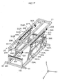
- Fig. 17 shows an exemplary configuration in which rotary dampers 361-364 and racks 365 and 366 that mesh with the dampers are attached in a vicinity of rollers 200-203.
- control is exerted on the rotary action of rollers 200-203 by rotary dampers 361-364 mounted thereto when, for example, parallelogram mechanism 35R is operated during the driving of the turning bed, allowing for gentle and smooth rotation with a high degree of stability, and thus for turning operations to be performed safely.
- the viscosity-generating means may be other than rotary dampers 361-364.
- rotation-speed controller mechanisms such as known friction clutch mechanisms or centrifugal brake mechanisms in same locations as rotary rollers 361-364.
- rotary dampers 361-364 can be formed integrally with respective rollers 200-203.
- the middle and side parts of the bed frame are each divided into four sections in a longitudinal direction, and these sections are coupled together.
- the present invention is, of course, not limited to this configuration, it being possible to divide the bed frame into a different number of sections.
- the platform, when structured from a coupled frame as in embodiment 1, preferably is divided into four or more sections corresponding to the upper body, lower back, and upper/lower leg regions, since this allows for subtle adjustment of the bed frame so as to at least accommodate postural changes when the care recipient is sleeping, for example.
- the side members may also be divided in the longitudinal direction ( x direction) and the resultant sections linked together, thus allowing postural changes to be carried out while cradling the care recipient to provide support.
- actuator drive methods may be used, an example of which is a rotational method.
- driving sources may be used, examples of which include actuators that operate using pneumatic or hydraulic methods, for example.
- embodiment 1 only relates to postural changes from a supine to a left lateral position, it is, of course, possible to similarly perform postural changes in the opposite direction or from supine to right lateral positions.
- turning bed 1 of embodiment 1 is not limited only to care recipients such as bedridden patients, and can also be used as a general-purpose bed.
- the mechanism consisting of coupled platforms 11a-11d and actuators M1 and M2 for obtaining a flexion position is disposed independently of parallelogram mechanisms 35R and 35L on either side of turning bed 1, it is also possible to drive these mechanisms selectively in order to separately raise the back/knees or tilt/elevate the bed surface.
- the controller of the turning bed was an infrared type or a cable/wireless type having a cord
- the present invention is not limited to this configuration, it being possible to perform drive controls using speech recognition.
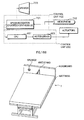
- Fig .18A is a block diagram showing a configuration for performing drive controls using speech recognition.
- the speech recognition unit includes a microphone 702 as an input device and a speaker 703 as an output device, and is constituted from a control unit 700 that includes a speech recognition device 701 consisting of a single-chip microcomputer, and control unit 600 that includes CPU 601 and motor driver 603 for driving the actuators.
- Speaker 703 is provided for announcing operations to the bed user before the operations are performed.
- a predetermined number of vocabularies e.g.
- Fig.18B is a perspective view of a turning bed having a microphone (speech recognition input device) attached thereto.
- a microphone speech recognition input device
- FIG.18B Schematically shown in the present embodiment is a configuration in which platform 11a at the head of the bed, to which a headboard is fitted, is equipped with a microphone having a flexible stand. This allows the microphone to always be positioned close to the care recipient's mouth even when the bed is driven.
- a lavalier microphone may be used in place of the microphone stand.
- Fig.19 shows an exemplary structural improvement in a vicinity of platform 11d.
- Platform 11d and adjustable stage 20 shown in Fig.19 are coupled together with slide-roller mechanisms 115R/115L provided therebetween. This effectively prevents any play between platform 11d and adjustable stage 20. Note that although the structure in a vicinity of platform 11d shown in Fig.19 differs from that shown in Fig.1, the fundamental structure of the bed is the same.
- side frame parts 21R/21L are fixed in place by two frame parts 210 and 211, which are in turn secured in place by frame parts 212R/212L.
- frame parts 212R/212L On platform 11d are disposed rollers 113R/113L, which are fitted into slide channels 213R/213L on frame parts 212R/212L so to travel back and forth within the channels.
- Two frame parts 111R/111L are disposed on the inside of frame parts 110R/110L, which form the outer frame of platform 11d, and rollers 113R/113L are attached to frame parts 111R/111L via triangular slide chips 112R/112L and roller stands 114R/1L4L. While rollers 113R/113L are normally (i.e. bed in horizontal position) removed from slide channels 213R/213L, when the bed is driven the sloped surface of slide chips 112R/112L comes in contact with slide blocks 116R/116L and rollers 113R/113L fit into slide channels 213R/213L. Slide chips 112R/112L and slide blocks 116R/116L are made from a hard resin material having favorable sliding properties.
- rollers 113R/113L are positioned freely outside of slide channels 213R/213L when forming a flat bed surface (Fig.20A) , and then as platform 11d inclines to form the Gatch position, the sloped surface of slide chips 112R/112L slide over slide blocks 116R/116L (Fig.20B). As the slope of platform 11d becomes steeper, rollers 113R/113L fit into slide channels 213R/213L with the sloped surface of slide chips 112R/112L being guided by slide blocks 116R/116L.
- slide roller mechanisms 115R/115L may be provided in the present invention to stabilize bed operations.
- Described here is an exemplary construction of a mattress suitable for use with a turning bed as described above.
- FIG. 21 shows an exemplary construction of a turning bed mattress.
- Mattress 400 which is basically made from a urethane material, has a hybrid structure formed from a composite material in which a relatively soft material is used for a section 401, which corresponds to platforms 11a-11d of the turning bed, and a relatively hard material used for sections 402R/402L, which correspond to side members 12Ra-12Rd/12La-12Ld.
- mattress 400 having this construction, it is firstly possible to support the posture of a care recipient lying horizontally on the mattress using section 401 of the mattress surface made from the relatively soft material. Secondly, when the bed is driven, the care recipient can expect postural changes to be performed while being gently supported, as a result of sections 402R/402L of the mattress surface being made from the relatively hard material giving to fit the shape of the side of the body.
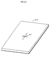
- Fig. 22 shows an exemplary construction of a turning bed mattress.
- an alignment mark 411 in the shape of a cross that marks a position corresponding to the care recipient's buttock region, thus enabling the care recipient to lie in an optimal position.
- Alignment mark 411 may be printed, embroidered, or the like on the mattress. This additional measure results in a turning bed of the present invention capable of performing even safer and more effective postural changes.
- the pattern of alignment mark 411 may, of course, be other than that shown in Fig.22.
- an alignment mark may be printed on a mattress sheet or the like.
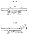
- Figs.22A and 22B are sectional views showing an exemplary construction of a turning bed mattress.
- mattress 420 has slits 421 and 422 formed in a thickness direction thereof, the position of the slits corresponding to the joints coupling platforms 11 to side members 12R/12L,
- slits 421 and 422 in mattress 420 open up when side members 12R or 12L are raised, forming a mattress surface having a natural slope by smooth operations, and facilitating postural changes.
- Fig. 24 shows an exemplary construction of the underside of a turning bed mattress.
- a characteristic of mattress 430 shown in this diagram is the attachment of hooks 431R/431L on both sides of the mattress at positions corresponding to the knee region (i.e. side members 12Rc/12Lc) when the care recipient is lying down, these hooks being designed to mate with the meshed surface of side members 12Rc/12Lc.
- hooks 431R/431L may be provided at positions other than the edge of mattress 430, the positions shown in Fig.24 are preferable since they most effectively prevent pinching of the mattress. Also, hooks 431R/431L may be provided on a sheet or the like covering mattress 430, rather than directly on mattress 430. Since sheets are more likely to get pinched than mattress 430, this configuration makes it possible to effectively resolve problems relating to pinching.
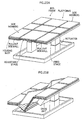
- Fig.25A is a perspective view showing a structure of a turning bed in an embodiment 2.
- a pair of columnar direct-acting actuators is disposed within a rectangular fixed stage, and a bed frame supported by an adjustable stage is positioned on top of the actuators.
- the platforms as in embodiment 1, are constructed as coupled platforms that are coupled together by a plurality of joints corresponding to the care recipient's upper body, hip, upper leg, and lower leg regions. Of these, the section corresponding to the upper-leg board is secured to the adjustable frame, which has a frame construction equivalent to the overall size of the platforms.
- a drive unit that includes an actuator mechanism for forming a flexion position.
- Housing slots are formed in the side members.
- the housing slots are partitioned in a longitudinal direction of the bed, and pullout sidewalls that are coupled to one another are housed in the housing slots.
- the side members are coupled to the adjustable stage supporting the platforms via the pullout sidewalls.
- the pullout sidewalls are biased in the direction of the housing slots by tension springs or the like, and are automatically housed in the housing slots when a force pulling the pullout sidewalls out of the housing slots weakens.
- a flexion position is firstly formed using the coupled platforms when the bed is driven, as shown in Fig.25B.
- One of the columnar direct-acting actuators then operates to lower the set of side members positioned thereabove. This has the effect of tilting the adjustable stage, which also brings the coupled platforms down at an angle. This results in the pullout sidewalls being pulled toward the coupled platforms from the respective housing slots at the lowered end of the tilted adjustable stage, raising the pullout sidewalls relative to the coupled platforms; that is, the pullout sidewalls at the lower end hangs from the coupled platforms with the angle between the two narrowed.
- the side members housing these pullout sidewalls are placed in a raised state relative to the coupled platforms. This achieves the effect of supporting the side of the care recipient's body with the pullout sidewalls while keeping the care recipient in the flexion position, thereby allowing for postural changes to be performed excellently, as in embodiment 1.
- Figs.26A to 26F show a structure of a turning bed in an embodiment 3.
- the turning bed in embodiment 3 which can be used with general-purpose beds, is constituted by laying an air mattress formed from a plurality of airbags on a general-purpose bed.
- a characteristic of this turning bed is the use of an air pump (not depicted) to supply/discharge air independently for each airbag via an air hose.
- the air hose has a valve that is controlled to open/close by a control unit (not depicted), thus controlling the inflation/deflation of respective airbags .
- the airbags are, as one example, partitioned into upper body (double layer), lower back (double layer), upper leg, lower leg, and both sides of the bed so as to correspond to the joints of the care recipient's body.
- a turning bed having the above structure is normally used with a mattress or the like placed over the air mattress.
- the upper airbags on both sides of the bed are firstly inflated (Fig.26A ⁇ 26C).
- the care recipient is placed in the flexion position by tilting the airbags corresponding to the upper body and lower back in a longitudinal direction, and inflating the airbags corresponding to the upper and lower leg regions so as form a knee break (Fig.26D).
- embodiment 3 achieves substantially the same effects as embodiments 1 and 2.
- embodiment 3 shows an example using a general-purpose bed
- the excellent portability of embodiment 3 means that the above turning bed can, in addition to being applied to a variety of general-purpose beds, also be laid directly on the floor (i.e. directly over tatami, carpet or the like).
- Described here are safety fittings suitable for use with a turning bed as in the above embodiments.
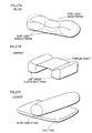
- Fig.27A shows a pillow for use with a turning bed. A middle part of the pillow is depressed relative to the both sides, this depression being designed to fit the care recipient's head.
- Fig.27B shows an armrest (cushion) for use with a turning bed.
- This armrest is formed from left and right columnar elbow-rest pads coupled to a band-shaped sheet.
- the sides of the care recipient when lying on the bed are placed between the elbow-rest pads.
- this armrest for a turning bed can also be expected to effectively prevent the care recipient from being sandwiched/pressed in on the sides when the bed is driven.
- Fig. 27C shows a legrest (cushion) for use with a turning bed.
- This legrest is formed from a columnar knee/ankle pad joined to a band-shaped calf pad. To use the legrest, the knee/ankle pad is sandwiched between both legs and the calves are positioned on the calf pad so that the care recipient's heels are suspended above the bed surface.
- Use of this legrest allows the care recipient's knees and ankles to be kept together at all times whether the bed is stationary or moving, effectively preventing the occurrence of decubitus ulcers.
- the load on the care recipient's heels is also lightened, effectively preventing decubitus ulcers in the heel region.
- Figs. 28A to 28C show gloves for use with a turning bed. These gloves are secured safely in front of the care recipient, so as not to interfere with arm movement when the turning bed is driven.
- the methods for securing the gloves include, as shown in the diagrams, lining them up side-by-side in a width direction of the bed (Fig.28A/28B), and arranging them together in a longitudinal direction of the bed (Fig.28C).
- the gloves preferably are used together with the above armrest to increase effectiveness.
- An adjustable bed according to the present invention can be used as a nursing care bed or a reclining bed.
Landscapes
- Health & Medical Sciences (AREA)
- Nursing (AREA)
- Life Sciences & Earth Sciences (AREA)
- Animal Behavior & Ethology (AREA)
- General Health & Medical Sciences (AREA)
- Public Health (AREA)
- Veterinary Medicine (AREA)
- Invalid Beds And Related Equipment (AREA)
Applications Claiming Priority (5)
| Application Number | Priority Date | Filing Date | Title |
|---|---|---|---|
| JP2002046936 | 2002-02-22 | ||
| JP2002046936 | 2002-02-22 | ||
| JP2002245647 | 2002-08-26 | ||
| JP2002245647A JP2003310668A (ja) | 2002-02-22 | 2002-08-26 | 可動ベッド |
| PCT/JP2003/001518 WO2003073973A1 (en) | 2002-02-22 | 2003-02-14 | Movable bed |
Publications (2)
| Publication Number | Publication Date |
|---|---|
| EP1486191A1 true EP1486191A1 (de) | 2004-12-15 |
| EP1486191A4 EP1486191A4 (de) | 2007-02-14 |
Family
ID=27790917
Family Applications (1)
| Application Number | Title | Priority Date | Filing Date |
|---|---|---|---|
| EP03705137A Withdrawn EP1486191A4 (de) | 2002-02-22 | 2003-02-14 | Bewegliches bett |
Country Status (7)
| Country | Link |
|---|---|
| US (1) | US7246389B2 (de) |
| EP (1) | EP1486191A4 (de) |
| JP (1) | JP2003310668A (de) |
| CN (1) | CN100417368C (de) |
| AU (1) | AU2003211974A1 (de) |
| TW (1) | TWI230060B (de) |
| WO (1) | WO2003073973A1 (de) |
Cited By (14)
| Publication number | Priority date | Publication date | Assignee | Title |
|---|---|---|---|---|
| GB2436198A (en) * | 2006-03-15 | 2007-09-19 | Steven Bowbrick | Tilting examination chair |
| EP1810650A3 (de) * | 2006-01-19 | 2008-05-07 | Hill-Rom Services, Inc. | Patientenliegevorrichtung mit Autokontur |
| WO2008139191A1 (en) | 2007-05-15 | 2008-11-20 | Genie Care | Turning platform |
| WO2009132843A1 (de) * | 2008-04-29 | 2009-11-05 | Martin Teschner | Steuerbares krankenbett |
| WO2009144338A1 (es) * | 2008-05-29 | 2009-12-03 | Nido Educa, S.L. | Cuna multifuncional para bebés |
| WO2010145934A1 (de) | 2009-06-18 | 2010-12-23 | Isko Koch Gmbh | Seitenlagerungsbett |
| WO2011144767A1 (es) * | 2010-05-18 | 2011-11-24 | Industrias Tobia, S.A. | Cama hospitalaria inteligente y método de funcionamiento de la misma |
| FR2972628A1 (fr) * | 2011-03-15 | 2012-09-21 | Antoine Ancelet | Support articule et procede de realisation et utilisation |
| DK178222B1 (en) * | 2014-12-03 | 2015-08-31 | Gdv Technology Aps | New bed system that can be attached to a hospital bed |
| WO2017121911A1 (es) | 2016-01-16 | 2017-07-20 | Gerinet, S.L.U. | Cama con bastidor móvil. |
| GB2552086A (en) * | 2017-06-19 | 2018-01-10 | Apex Health Care Mfg Inc | Motorized bed |
| CN110381905A (zh) * | 2017-03-02 | 2019-10-25 | 法兰西床株式会社 | 床装置 |
| US11446190B2 (en) | 2016-04-06 | 2022-09-20 | Careturner A/S | Bed system for attachment to a hospital bed for turning a patient |
| IT202300017814A1 (it) * | 2023-08-30 | 2025-03-02 | Starnem Srl | Sistema di ausilio per la movimentazione di pazienti. |
Families Citing this family (86)
| Publication number | Priority date | Publication date | Assignee | Title |
|---|---|---|---|---|
| JP2003310668A (ja) * | 2002-02-22 | 2003-11-05 | Sanyo Electric Co Ltd | 可動ベッド |
| WO2004024051A1 (ja) * | 2002-07-24 | 2004-03-25 | France Bed Co., Ltd. | 起床式ベッド装置及びマットレス |
| JP3960885B2 (ja) * | 2002-08-21 | 2007-08-15 | 三洋電機株式会社 | 可動ベッド用マット |
| JP2005205164A (ja) * | 2003-12-26 | 2005-08-04 | Tsuneo Yamamoto | 身体位置変換形寝台装置 |
| FR2872030B1 (fr) * | 2004-06-24 | 2006-08-25 | Centre Nat Rech Scient Cnrse | Dispositif de prevention d'escarre |
| US7757318B2 (en) | 2004-09-13 | 2010-07-20 | Kreg Therapeutics, Inc. | Mattress for a hospital bed |
| US7676862B2 (en) | 2004-09-13 | 2010-03-16 | Kreg Medical, Inc. | Siderail for hospital bed |
| US7743441B2 (en) | 2004-09-13 | 2010-06-29 | Kreg Therapeutics, Inc. | Expandable width bed |
| US7779494B2 (en) | 2004-09-13 | 2010-08-24 | Kreg Therapeutics, Inc. | Bed having fixed length foot deck |
| CN100579497C (zh) * | 2004-12-28 | 2010-01-13 | 奥林巴斯株式会社 | 胶囊型医疗装置用导入辅助装置 |
| US7716761B1 (en) * | 2005-07-06 | 2010-05-18 | Gilstad Dennis W | Adaptive positioning system |
| US7237286B1 (en) * | 2006-01-20 | 2007-07-03 | Kim Willie W | Articulating bed |
| US20070234482A1 (en) * | 2006-04-05 | 2007-10-11 | Scot Wright | Mattress extension system |
| GB0700372D0 (en) * | 2007-01-09 | 2007-02-14 | Guy S And St Thomas Nhs Founda | Device and methods of using device |
| KR100893470B1 (ko) | 2007-09-10 | 2009-04-17 | 윤태범 | 틸트 침대 |
| US7712168B2 (en) | 2007-09-21 | 2010-05-11 | Kim Willie W | Articulating bed and method of using the same |
| US7845034B2 (en) | 2007-09-21 | 2010-12-07 | Kim Willie W | Articulating bed and method of operating the same |
| US7761942B2 (en) * | 2007-10-09 | 2010-07-27 | Bedlab, Llc | Bed with adjustable patient support framework |
| US20090094745A1 (en) * | 2007-10-14 | 2009-04-16 | Eduardo Rene Benzo | Modulating Support Surface to Aid Patient Entry and Exit |
| US7716762B2 (en) * | 2007-10-14 | 2010-05-18 | Bedlab, Llc | Bed with sacral and trochanter pressure relieve functions |
| US7886379B2 (en) * | 2007-10-14 | 2011-02-15 | Bedlab, Llc | Support surface that modulates to cradle a patient's midsection |
| US20090241262A1 (en) * | 2008-03-28 | 2009-10-01 | Frank Jehn | Mobile veterinary surgical table incorporating a dental operatory |
| US20090278486A1 (en) * | 2008-05-06 | 2009-11-12 | Chun-Sheng Lin | Motor Controlling Method for Rotating a Lift Arm of an Adjustable Bed according to a Predetermined Bending Angle of the Lift Arm |
| US9119753B2 (en) | 2008-06-27 | 2015-09-01 | Kreg Medical, Inc. | Bed with modified foot deck |
| DE102009039367A1 (de) * | 2009-08-29 | 2011-03-03 | Göddert, Marco | Bett zur Unterstützung des Aufrichtens |
| CN103533865A (zh) * | 2011-07-25 | 2014-01-22 | 李大熏 | 自由折叠床、用于该自由折叠床的位移机构及动作方法 |
| KR101392948B1 (ko) * | 2011-07-25 | 2014-05-09 | 이대훈 | 자유 접이 침대의 동작방법 |
| WO2013015584A2 (ko) * | 2011-07-25 | 2013-01-31 | Lee Dae Hun | 자유 접이 침대, 이를 위한 변위수단 및 동작방법 |
| KR101200721B1 (ko) * | 2011-07-25 | 2012-11-12 | 이대훈 | 자유 접이 침대 |
| JP5965491B2 (ja) * | 2011-10-20 | 2016-08-03 | ファーノ−ワシントン・インコーポレーテッド | 死体防腐処置台のための作業面拡張部及び同部を含む死体防腐処置台 |
| CN102512298B (zh) * | 2011-12-21 | 2014-07-30 | 安延全 | 护理床 |
| KR101318724B1 (ko) * | 2012-01-20 | 2013-10-16 | 연세대학교 산학협력단 | 지능형 케어를 위한 가변 침상 |
| US20150136146A1 (en) * | 2012-05-22 | 2015-05-21 | Hill-Rom Services, Inc. | Adverse event mitigation systems, methods and devices |
| EP2892490B1 (de) * | 2012-09-05 | 2020-05-06 | Stryker Corporation | Patientenliege |
| WO2014174965A1 (ja) * | 2013-04-25 | 2014-10-30 | パラマウントベッド株式会社 | ベッド装置、及び、ベッド装置の制御方法 |
| DE102013105869A1 (de) * | 2013-06-06 | 2014-12-11 | MAQUET GmbH | Vorrichtung und Verfahren zum Steuern eines Operationstischs |
| US10179077B2 (en) | 2014-04-18 | 2019-01-15 | Kreg Medical, Inc. | Patient support with stand-up and sit features |
| US10765222B2 (en) * | 2014-05-30 | 2020-09-08 | Ultra-Mek, Inc. | Bed with liftable mattress and storage cavity |
| CN104161637A (zh) * | 2014-08-02 | 2014-11-26 | 温州医科大学 | 新型自助翻身器装置 |
| US9724254B2 (en) * | 2014-10-03 | 2017-08-08 | Daryl L. Cole | Adjustable bed |
| CN104434436B (zh) * | 2014-11-10 | 2017-10-24 | 北京康拓医疗仪器有限公司 | 一种侧翻床 |
| US9648959B2 (en) | 2015-04-09 | 2017-05-16 | Larry Frydman | Single clasp leg pillow with extension |
| US11058227B2 (en) | 2015-04-23 | 2021-07-13 | Sealy Technology, Llc | Systems and methods for adjusting the firmness and profile of a mattress assembly |
| CN105030454A (zh) * | 2015-07-01 | 2015-11-11 | 耿宏柱 | 多用途自动翻身床 |
| CN105232259A (zh) * | 2015-11-23 | 2016-01-13 | 中国医学科学院北京协和医院 | 早产婴儿护理可变体位保育床 |
| US10154931B1 (en) * | 2015-12-01 | 2018-12-18 | Vanntec Llc | In situ bed chair |
| JP6968518B2 (ja) * | 2016-03-09 | 2021-11-17 | パラマウントベッド株式会社 | ベッド装置 |
| CN106038164A (zh) * | 2016-07-01 | 2016-10-26 | 广东正美家具科技有限公司 | 一种按摩和卧姿调整多功能装置 |
| US10881567B2 (en) | 2016-10-28 | 2021-01-05 | Stryker Corporation | Patient support apparatus |
| US10744053B2 (en) | 2016-12-07 | 2020-08-18 | Stryker Corporation | Haptic systems and methods for a user interface of a patient support apparatus |
| JP6388239B2 (ja) * | 2016-12-28 | 2018-09-12 | パナソニックIpマネジメント株式会社 | 仰臥台 |
| US10441084B2 (en) * | 2017-02-18 | 2019-10-15 | Ulife Healthcare Inc. | Lightweight modular bed |
| TWM540570U (zh) * | 2017-02-18 | 2017-05-01 | Ulife Healthcare Inc | 輕量化床架裝置 |
| WO2018191760A1 (en) * | 2017-04-12 | 2018-10-18 | Schell Mary Ann | Cradling bed assembly and related method |
| US11439247B2 (en) * | 2017-04-12 | 2022-09-13 | Mary Ann Schell | Bed frame for side sleeping |
| CN109077870A (zh) * | 2017-06-14 | 2018-12-25 | 黄天炎 | 智能自动护理床 |
| GB201717674D0 (en) * | 2017-10-27 | 2017-12-13 | Frontier Therapeutics Ltd | Patient turning apparatus |
| US11116679B2 (en) * | 2017-12-13 | 2021-09-14 | Vandette B. Carter | Bed bound patient turning device |
| TWM559120U (zh) * | 2018-02-01 | 2018-05-01 | Ulife Healthcare Inc | 電動傢俱床 |
| DE102018108867A1 (de) * | 2018-04-13 | 2019-10-17 | Dewertokin Gmbh | Steuereinrichtung für einen Möbelantrieb und Verfahren zum Steuern eines Möbelantriebs |
| CN108852690B (zh) * | 2018-08-01 | 2020-06-02 | 湖南佩蕾斯特科技有限公司 | 一种多功能康复护理床 |
| US11470980B2 (en) | 2018-08-22 | 2022-10-18 | Fredman Bros. Furniture Company, Inc. | Multi-function device for an adjustable bed system |
| CN110856580A (zh) * | 2018-08-22 | 2020-03-03 | 台山市恒生五金家具有限公司 | 一种床 |
| JP2020031787A (ja) * | 2018-08-28 | 2020-03-05 | 株式会社ケープ | エアマット制御装置 |
| DE102018128423A1 (de) * | 2018-11-13 | 2020-05-14 | Minebea Intec Bovenden GmbH & Co. KG | Adaptiver Herausfallschutz für Betten |
| JP6818059B2 (ja) * | 2018-11-15 | 2021-01-20 | フランスベッド株式会社 | ベッド装置 |
| US11389352B2 (en) * | 2019-04-07 | 2022-07-19 | Sleepme Inc. | Devices and methods to help prevent decubitus ulcers |
| CN110013396B (zh) * | 2019-04-25 | 2020-09-25 | 宿州市华康医疗器械有限公司 | 一种智能医疗的护理床 |
| CN112386047A (zh) * | 2019-08-15 | 2021-02-23 | 麒盛科技股份有限公司 | 一种三折叠电动床 |
| JP7391291B2 (ja) | 2019-10-11 | 2023-12-05 | 船井電機株式会社 | マットレス |
| JP7214887B2 (ja) * | 2019-11-07 | 2023-01-30 | 川崎重工業株式会社 | 介護用ベッドシステム及び介護用ベッド姿勢変更装置 |
| CN111772414B (zh) * | 2020-07-17 | 2022-08-19 | 吉荣家具有限公司 | 一种带有储物箱的学生床 |
| CN111956416B (zh) * | 2020-08-11 | 2021-06-04 | 常州工学院 | 一种满足舒适度要求且方便上下床的助老床 |
| CA3093143A1 (en) * | 2020-09-15 | 2022-03-15 | Domores Inc. | Lit therapeutique a geometrie variable tournant et centralisant un patient immobile pour prevenir la plaie de lit ainsi que methode associee |
| CN113069289A (zh) * | 2021-03-23 | 2021-07-06 | 河南科技大学第一附属医院 | 一种神经内科护理床 |
| KR102298043B1 (ko) * | 2021-04-22 | 2021-09-03 | 이호범 | 오픈 셀 구조의 침대 |
| CN113384409A (zh) * | 2021-06-23 | 2021-09-14 | 娄底职业技术学院 | 一种电子自控翻身护理床以及自动翻身方法 |
| US12370107B2 (en) * | 2021-07-30 | 2025-07-29 | TurnCare, Inc. | Network-accessible controllers for managing pressure-mitigation devices and approaches to incorporating the same into existing infrastructure |
| CN117979936A (zh) * | 2021-09-08 | 2024-05-03 | 柏灵老年护理有限公司 | 用于翻转患者的床 |
| CN114028132B (zh) * | 2021-12-15 | 2023-09-08 | 郑州大学第一附属医院 | 一种胃镜肠镜诊疗用辅助调节床 |
| CN115039989A (zh) * | 2022-06-17 | 2022-09-13 | 慕思健康睡眠股份有限公司 | 床垫变形调整方法、装置、床垫及存储介质 |
| CN116059052B (zh) * | 2023-02-08 | 2023-09-19 | 厚福医疗装备有限公司 | 一种半卧位可调的大角度侧翻护理床 |
| JP7518493B1 (ja) | 2023-05-27 | 2024-07-18 | 諒吉 渡邊 | 排泄とシャワー浴が出来る側臥位自動寝返り介護用ベッド。 |
| JP2025007328A (ja) * | 2023-06-30 | 2025-01-17 | 株式会社プラッツ | ユーザ検出システム、ユーザ検出システムに含まれるセンサ装置、及び、ユーザ検出システムを備えたベッド |
| US20250064219A1 (en) * | 2023-08-22 | 2025-02-27 | Iowa State University Research Foundation, Inc. | Dog recumbency rest rocker bed |
| CN117618203A (zh) * | 2024-01-25 | 2024-03-01 | 山东中泰医疗器械有限公司 | 一种便于调整姿态的护理装置 |
Family Cites Families (63)
| Publication number | Priority date | Publication date | Assignee | Title |
|---|---|---|---|---|
| US554580A (en) * | 1896-02-11 | Weight | ||
| US1021335A (en) * | 1911-05-11 | 1912-03-26 | Thomas C Robinson | Invalid-bedstead. |
| US1559119A (en) * | 1922-04-03 | 1925-10-27 | Bejamin F Schmidt | Mattress retainer |
| US1842873A (en) * | 1930-07-29 | 1932-01-26 | Mary E Leeking | Mattress holder |
| US2588854A (en) * | 1946-12-11 | 1952-03-11 | Helen E Lang | Mattress holder |
| US2995762A (en) * | 1960-01-18 | 1961-08-15 | Miller Herman Inc | Appointments for beds |
| US3474781A (en) * | 1968-08-07 | 1969-10-28 | Medical Specialties Inc | Restraining device for bedridden persons |
| NL168410C (nl) * | 1972-07-13 | 1982-04-16 | Tokyo Shibaura Electric Co | Bedplaat. |
| US4127906A (en) * | 1976-07-15 | 1978-12-05 | Zur Henry C | Adjustable bed-chair |
| US4287620A (en) * | 1978-06-02 | 1981-09-08 | Zur Henry C | Multi-feature and variable function body supporting assembly and sideguards |
| US4135504A (en) * | 1977-03-24 | 1979-01-23 | Spann Donald C | Orthopedic support |
| US4225988A (en) * | 1979-01-30 | 1980-10-07 | Cary George R | Ortho-turn bed |
| US4372299A (en) * | 1979-09-13 | 1983-02-08 | Fixel Irving E | Abduction pillow with storage cavity |
| US4726083A (en) * | 1982-04-19 | 1988-02-23 | Hoshall Vicki S | Boxspring-mattress set employing slide-preventing means |
| US5479665A (en) * | 1983-09-09 | 1996-01-02 | Cassidy; Joseph P. | Automated tri-fold bed |
| US4662366A (en) * | 1985-05-20 | 1987-05-05 | Tari Lynda G | Immobilizing arm support |
| US4899404A (en) * | 1985-11-25 | 1990-02-13 | Galumbeck Michael H | Elevation system for a bed assembly |
| EP0323460A1 (de) * | 1986-08-15 | 1989-07-12 | Butcher, Ian Donald | Körperstützanordnung |
| US4683601A (en) * | 1986-09-22 | 1987-08-04 | Herbert Lagin | Medical pillow |
| JPH02111426A (ja) | 1988-10-18 | 1990-04-24 | Nippon Oil & Fats Co Ltd | 可溶化組成物 |
| US4910818A (en) * | 1989-03-16 | 1990-03-27 | Robert Grabill | Leg positioning assembly |
| FR2652261B1 (fr) * | 1989-09-25 | 1994-05-20 | Michel Gaffe | Dispositif a but preventif et therapeutique en fonction d'un positionnement determine des membres inferieurs. |
| US5125122A (en) * | 1990-12-26 | 1992-06-30 | Chen Mau Shen | Tiltable bed mechanism |
| US5117522A (en) * | 1991-03-27 | 1992-06-02 | Everett Peter M | Leg pillow |
| US5125123A (en) * | 1991-05-07 | 1992-06-30 | Engle Lawrence J | Sleep comforter leg pillow |
| JP3045198B2 (ja) | 1991-08-02 | 2000-05-29 | 日本電信電話株式会社 | 共鳴トンネル型フォトトランジスタ |
| JPH0695966B2 (ja) | 1991-12-27 | 1994-11-30 | 正雄 瓜生 | 体位変換用傾斜滑り止めベッド |
| US5224228A (en) * | 1992-06-17 | 1993-07-06 | Larrimore James R | Longitudinally split, motor operated butterfly bed |
| GB2272367B (en) * | 1992-11-16 | 1996-01-31 | Hung Yung Feng | A multi-function and automatic sick bed |
| US5400448A (en) * | 1993-10-15 | 1995-03-28 | Zwickey; Wayne C. | Ambulance gurney mattress |
| JPH07116199A (ja) | 1993-10-26 | 1995-05-09 | Molten Corp | エアマット |
| US5535464A (en) * | 1993-12-02 | 1996-07-16 | Salonica; Frank T. | Sectional invalid bed with disposable waste container |
| JPH07163623A (ja) | 1993-12-10 | 1995-06-27 | Yoshiro Nakamatsu | 床ずれ防止及び/又は内臓器官活性化ベッド |
| US5392479A (en) * | 1994-01-28 | 1995-02-28 | Liao; Yu-Kuen | Multipurpose sickbed |
| US5502853A (en) * | 1994-02-14 | 1996-04-02 | Sequin Hospital Bed Corp. | Bed frame with independently oscillating cradle |
| US5625913A (en) * | 1994-02-14 | 1997-05-06 | Singleton; William H. | Oscillatory bed |
| US5500964A (en) * | 1994-03-09 | 1996-03-26 | National Health Equipment, Inc. | Patient manipulating kit and method of converting a hospital bed to a patient manipulation apparatus |
| JP2987290B2 (ja) * | 1994-05-02 | 1999-12-06 | フランスベッド株式会社 | ベッド装置 |
| CN2202518Y (zh) * | 1994-08-12 | 1995-07-05 | 吴锦荣 | 多功能自动翻身床 |
| US6038718A (en) * | 1994-08-15 | 2000-03-21 | Midmark Corporation | Surgical table |
| US20010027577A1 (en) * | 1995-06-07 | 2001-10-11 | Frydman Larry G. | Orthopedic support pillow |
| US6154905A (en) * | 1995-06-07 | 2000-12-05 | Frydman; Larry G. | Orthopedic support pillow |
| US5549121A (en) * | 1995-07-25 | 1996-08-27 | Vinci; Vincent A. | Surgical arm support |
| CN2265184Y (zh) * | 1996-05-22 | 1997-10-22 | 曾庆祥 | 医用全自动侧位翻转床 |
| US5746218A (en) * | 1996-08-02 | 1998-05-05 | Edge; David A. | Therapeutic pillow |
| US5878453A (en) * | 1997-12-05 | 1999-03-09 | Stokes; Lowell | Leg support pillow |
| US5871457A (en) * | 1997-12-19 | 1999-02-16 | Smith & Nephrew, Inc. | Knee positioning support |
| JPH11239524A (ja) | 1997-12-27 | 1999-09-07 | Kanayama Kosan Kk | 介護用ベッド及び介護用ベッドのマットレス |
| JP3560800B2 (ja) | 1998-01-27 | 2004-09-02 | フランスベッド株式会社 | エアーマットレス装置およびベッド装置 |
| JP2001008979A (ja) | 1999-06-29 | 2001-01-16 | Kanayama Kosan Kk | 介護用ベッド及び介護用ベッドのマットレス |
| JP2001293037A (ja) | 2000-04-13 | 2001-10-23 | Fukuju Sangyo Kk | 可動ベッド |
| CA2337994C (en) * | 2001-02-26 | 2011-07-05 | Probed Medical Technologies Inc. | Bed with adjustable positions |
| SE518670C2 (sv) | 2001-03-12 | 2002-11-05 | Xdin Ab Publ | Ställbar säng innefattande en centrallåda under madrassbotten till vilken är ansluten ett teleskopiskt benarrangemang |
| DE10127067A1 (de) * | 2001-05-23 | 2002-11-28 | Brose Fahrzeugteile | Kraftfahrzeugsitz |
| US6830050B1 (en) * | 2001-10-29 | 2004-12-14 | Rafi Bamdad | Method and device for applying pressure to the whole of the chest area of post chest surgery patients |
| JP2003310668A (ja) * | 2002-02-22 | 2003-11-05 | Sanyo Electric Co Ltd | 可動ベッド |
| WO2004024051A1 (ja) * | 2002-07-24 | 2004-03-25 | France Bed Co., Ltd. | 起床式ベッド装置及びマットレス |
| WO2004026211A1 (ja) * | 2002-08-29 | 2004-04-01 | Sanyo Electric Co., Ltd. | 可動ベッド |
| JP3957597B2 (ja) * | 2002-09-04 | 2007-08-15 | 三洋電機株式会社 | 可動ベッド |
| JP4712385B2 (ja) * | 2002-09-06 | 2011-06-29 | ヒル−ロム サービシーズ,インコーポレイティド | 病院ベッド |
| JP2004121837A (ja) * | 2002-09-11 | 2004-04-22 | Sanyo Electric Co Ltd | 可動ベッド |
| US6889396B2 (en) * | 2003-01-03 | 2005-05-10 | L&P Property Management Company | Adjustable bed mattress clip |
| US20050091749A1 (en) * | 2003-10-31 | 2005-05-05 | Humbles Frank F. | Surgical arm positioning pad |
-
2002
- 2002-08-26 JP JP2002245647A patent/JP2003310668A/ja active Pending
-
2003
- 2003-02-14 US US10/505,156 patent/US7246389B2/en not_active Expired - Fee Related
- 2003-02-14 EP EP03705137A patent/EP1486191A4/de not_active Withdrawn
- 2003-02-14 WO PCT/JP2003/001518 patent/WO2003073973A1/ja not_active Ceased
- 2003-02-14 CN CNB038043823A patent/CN100417368C/zh not_active Expired - Fee Related
- 2003-02-14 AU AU2003211974A patent/AU2003211974A1/en not_active Abandoned
- 2003-02-21 TW TW092103615A patent/TWI230060B/zh not_active IP Right Cessation
Cited By (25)
| Publication number | Priority date | Publication date | Assignee | Title |
|---|---|---|---|---|
| EP1810650A3 (de) * | 2006-01-19 | 2008-05-07 | Hill-Rom Services, Inc. | Patientenliegevorrichtung mit Autokontur |
| US8910329B2 (en) | 2006-01-19 | 2014-12-16 | Hill-Rom Services, Inc. | Patient support having auto contour |
| US8387184B2 (en) | 2006-01-19 | 2013-03-05 | Hill-Rom Services, Inc. | Auto contour handle apparatus |
| US8069513B2 (en) | 2006-01-19 | 2011-12-06 | Hill-Rom Services, Inc. | Patient support apparatus having auto contour |
| GB2436198A (en) * | 2006-03-15 | 2007-09-19 | Steven Bowbrick | Tilting examination chair |
| GB2449318B (en) * | 2007-05-15 | 2010-02-17 | Genie Care Ltd | Automatic patient turning apparatus |
| WO2008139191A1 (en) | 2007-05-15 | 2008-11-20 | Genie Care | Turning platform |
| US8776290B2 (en) | 2007-05-15 | 2014-07-15 | Genie Care | Turning platform |
| WO2009132843A1 (de) * | 2008-04-29 | 2009-11-05 | Martin Teschner | Steuerbares krankenbett |
| WO2009144338A1 (es) * | 2008-05-29 | 2009-12-03 | Nido Educa, S.L. | Cuna multifuncional para bebés |
| ES2330711B1 (es) * | 2008-05-29 | 2010-08-04 | Nido Educa, S.L. | Cuna multifuncional para bebes. |
| ES2330711A1 (es) * | 2008-05-29 | 2009-12-14 | Nido Educa, S.L. | Cuna multifuncional para bebes. |
| WO2010145934A1 (de) | 2009-06-18 | 2010-12-23 | Isko Koch Gmbh | Seitenlagerungsbett |
| EP2583652A4 (de) * | 2010-05-18 | 2015-09-23 | Ind Tobia S A | Intelligentes krankenhausbett und bedienungsverfahren dafür |
| WO2011144767A1 (es) * | 2010-05-18 | 2011-11-24 | Industrias Tobia, S.A. | Cama hospitalaria inteligente y método de funcionamiento de la misma |
| US8950026B2 (en) | 2010-05-18 | 2015-02-10 | Industrias Tobia, S.A. | Intelligent hospital bed and method for operating same |
| FR2972628A1 (fr) * | 2011-03-15 | 2012-09-21 | Antoine Ancelet | Support articule et procede de realisation et utilisation |
| DK178222B1 (en) * | 2014-12-03 | 2015-08-31 | Gdv Technology Aps | New bed system that can be attached to a hospital bed |
| WO2017121911A1 (es) | 2016-01-16 | 2017-07-20 | Gerinet, S.L.U. | Cama con bastidor móvil. |
| US11446190B2 (en) | 2016-04-06 | 2022-09-20 | Careturner A/S | Bed system for attachment to a hospital bed for turning a patient |
| CN110381905A (zh) * | 2017-03-02 | 2019-10-25 | 法兰西床株式会社 | 床装置 |
| EP3574880A4 (de) * | 2017-03-02 | 2021-02-17 | France Bed Co., Ltd. | Bettvorrichtung |
| GB2552086A (en) * | 2017-06-19 | 2018-01-10 | Apex Health Care Mfg Inc | Motorized bed |
| GB2552086B (en) * | 2017-06-19 | 2018-12-12 | Apex Health Care Mfg Inc | Motorized bed |
| IT202300017814A1 (it) * | 2023-08-30 | 2025-03-02 | Starnem Srl | Sistema di ausilio per la movimentazione di pazienti. |
Also Published As
| Publication number | Publication date |
|---|---|
| TWI230060B (en) | 2005-04-01 |
| CN1638711A (zh) | 2005-07-13 |
| AU2003211974A1 (en) | 2003-09-16 |
| EP1486191A4 (de) | 2007-02-14 |
| US7246389B2 (en) | 2007-07-24 |
| WO2003073973A1 (en) | 2003-09-12 |
| TW200304802A (en) | 2003-10-16 |
| CN100417368C (zh) | 2008-09-10 |
| JP2003310668A (ja) | 2003-11-05 |
| US20050160530A1 (en) | 2005-07-28 |
Similar Documents
| Publication | Publication Date | Title |
|---|---|---|
| US7246389B2 (en) | Adjustable bed | |
| EP1541109A1 (de) | Matratze für ein bewegliches bett | |
| US7730562B2 (en) | Patient support having powered adjustable width | |
| EP3089620B1 (de) | Verstellbares bettsystem mit geteiltem kopfteil | |
| US20050028289A1 (en) | Mattress | |
| US6957460B2 (en) | Mechanical system for operating the back and knee bottom sections of a bed or the like in an interlocked manner | |
| EP0262771B1 (de) | Umwendbares Bett | |
| JP2003527205A (ja) | 回転治療装置を有する病院ベッド | |
| CN109068856B (zh) | 斜倚式床 | |
| WO1988001158A1 (en) | A body supporting apparatus | |
| TW200306165A (en) | Method of controlling the coordinative lifting of bottom sections of lying furniture such as a bed | |
| EP3789002A1 (de) | Patientenliege | |
| EP1621172A2 (de) | Modulares Bettsystem | |
| JP5474286B2 (ja) | 椅子式マッサージ機 | |
| KR20030076329A (ko) | 침대 등의 앙와대의 연동승강 제어방법 | |
| KR20180129241A (ko) | 조립식 전동침대 | |
| JP7127011B2 (ja) | マットレスおよびベッド装置 | |
| JP7661016B2 (ja) | ボトム装置、ベッド装置及びボトム装置の制御方法 | |
| JP2002035052A (ja) | 介助用マット装置 | |
| US20250082523A1 (en) | Patient support apparatus and mattress therefor | |
| CN219743175U (zh) | 一种能够调整躺姿的充气式床垫 | |
| EP3225222A1 (de) | Verstellbares bett | |
| JPH07213561A (ja) | 医療介護システムにおけるベッド及びこれと組み合わされる患者移送装置並びにこれらを連結する連結装置及び連動操作装置 | |
| JP2004166987A (ja) | 介護用ベッド |
Legal Events
| Date | Code | Title | Description |
|---|---|---|---|
| PUAI | Public reference made under article 153(3) epc to a published international application that has entered the european phase |
Free format text: ORIGINAL CODE: 0009012 |
|
| 17P | Request for examination filed |
Effective date: 20040916 |
|
| AK | Designated contracting states |
Kind code of ref document: A1 Designated state(s): AT BE BG CH CY CZ DE DK EE ES FI FR GB GR HU IE IT LI LU MC NL PT SE SI SK TR |
|
| AX | Request for extension of the european patent |
Extension state: AL LT LV MK RO |
|
| A4 | Supplementary search report drawn up and despatched |
Effective date: 20070117 |
|
| REG | Reference to a national code |
Ref country code: DE Ref legal event code: 8566 |
|
| STAA | Information on the status of an ep patent application or granted ep patent |
Free format text: STATUS: THE APPLICATION HAS BEEN WITHDRAWN |
|
| 18W | Application withdrawn |
Effective date: 20080319 |