EP1486827B1 - Lithographischer Apparat und Verfahren zur Herstellung einer Vorrichtung - Google Patents
Lithographischer Apparat und Verfahren zur Herstellung einer Vorrichtung Download PDFInfo
- Publication number
- EP1486827B1 EP1486827B1 EP04253325A EP04253325A EP1486827B1 EP 1486827 B1 EP1486827 B1 EP 1486827B1 EP 04253325 A EP04253325 A EP 04253325A EP 04253325 A EP04253325 A EP 04253325A EP 1486827 B1 EP1486827 B1 EP 1486827B1
- Authority
- EP
- European Patent Office
- Prior art keywords
- liquid
- bubbles
- bubble
- substrate
- projection apparatus
- Prior art date
- Legal status (The legal status is an assumption and is not a legal conclusion. Google has not performed a legal analysis and makes no representation as to the accuracy of the status listed.)
- Expired - Lifetime
Links
- 238000004519 manufacturing process Methods 0.000 title claims description 8
- 239000007788 liquid Substances 0.000 claims description 231
- 239000000758 substrate Substances 0.000 claims description 103
- 239000002245 particle Substances 0.000 claims description 73
- 230000005855 radiation Effects 0.000 claims description 44
- 239000007789 gas Substances 0.000 claims description 38
- 238000001514 detection method Methods 0.000 claims description 26
- 238000000059 patterning Methods 0.000 claims description 19
- 230000009467 reduction Effects 0.000 claims description 19
- 230000005684 electric field Effects 0.000 claims description 17
- 238000007872 degassing Methods 0.000 claims description 12
- IJGRMHOSHXDMSA-UHFFFAOYSA-N Atomic nitrogen Chemical compound N#N IJGRMHOSHXDMSA-UHFFFAOYSA-N 0.000 claims description 11
- XLYOFNOQVPJJNP-UHFFFAOYSA-N water Substances O XLYOFNOQVPJJNP-UHFFFAOYSA-N 0.000 claims description 11
- 239000000463 material Substances 0.000 claims description 10
- XKRFYHLGVUSROY-UHFFFAOYSA-N Argon Chemical compound [Ar] XKRFYHLGVUSROY-UHFFFAOYSA-N 0.000 claims description 8
- 239000000203 mixture Substances 0.000 claims description 8
- 238000005286 illumination Methods 0.000 claims description 7
- 238000002955 isolation Methods 0.000 claims description 7
- 230000002238 attenuated effect Effects 0.000 claims description 5
- 239000001307 helium Substances 0.000 claims description 5
- 229910052734 helium Inorganic materials 0.000 claims description 5
- SWQJXJOGLNCZEY-UHFFFAOYSA-N helium atom Chemical compound [He] SWQJXJOGLNCZEY-UHFFFAOYSA-N 0.000 claims description 5
- 229910052786 argon Inorganic materials 0.000 claims description 4
- 229910001873 dinitrogen Inorganic materials 0.000 claims 1
- 238000007654 immersion Methods 0.000 description 45
- 238000000034 method Methods 0.000 description 16
- 238000003384 imaging method Methods 0.000 description 10
- 230000000694 effects Effects 0.000 description 9
- 239000010410 layer Substances 0.000 description 9
- 230000008901 benefit Effects 0.000 description 8
- 238000009826 distribution Methods 0.000 description 8
- 230000003287 optical effect Effects 0.000 description 8
- 239000011148 porous material Substances 0.000 description 6
- 230000008569 process Effects 0.000 description 6
- 238000011109 contamination Methods 0.000 description 5
- 239000012528 membrane Substances 0.000 description 5
- 229910052757 nitrogen Inorganic materials 0.000 description 5
- 238000010943 off-gassing Methods 0.000 description 5
- VYPSYNLAJGMNEJ-UHFFFAOYSA-N silicon dioxide Inorganic materials O=[Si]=O VYPSYNLAJGMNEJ-UHFFFAOYSA-N 0.000 description 5
- 230000009471 action Effects 0.000 description 4
- 238000004140 cleaning Methods 0.000 description 4
- 238000010586 diagram Methods 0.000 description 4
- 238000010438 heat treatment Methods 0.000 description 4
- 239000013307 optical fiber Substances 0.000 description 4
- 238000012545 processing Methods 0.000 description 4
- 239000007787 solid Substances 0.000 description 4
- OKTJSMMVPCPJKN-UHFFFAOYSA-N Carbon Chemical compound [C] OKTJSMMVPCPJKN-UHFFFAOYSA-N 0.000 description 3
- 230000002547 anomalous effect Effects 0.000 description 3
- QVGXLLKOCUKJST-UHFFFAOYSA-N atomic oxygen Chemical compound [O] QVGXLLKOCUKJST-UHFFFAOYSA-N 0.000 description 3
- 230000015556 catabolic process Effects 0.000 description 3
- 238000000576 coating method Methods 0.000 description 3
- 238000013461 design Methods 0.000 description 3
- 230000006870 function Effects 0.000 description 3
- 230000002209 hydrophobic effect Effects 0.000 description 3
- 238000001459 lithography Methods 0.000 description 3
- 239000001301 oxygen Substances 0.000 description 3
- 229910052760 oxygen Inorganic materials 0.000 description 3
- 230000002829 reductive effect Effects 0.000 description 3
- 239000000126 substance Substances 0.000 description 3
- 238000002604 ultrasonography Methods 0.000 description 3
- CURLTUGMZLYLDI-UHFFFAOYSA-N Carbon dioxide Chemical compound O=C=O CURLTUGMZLYLDI-UHFFFAOYSA-N 0.000 description 2
- FAPWRFPIFSIZLT-UHFFFAOYSA-M Sodium chloride Chemical compound [Na+].[Cl-] FAPWRFPIFSIZLT-UHFFFAOYSA-M 0.000 description 2
- 238000013019 agitation Methods 0.000 description 2
- 238000013459 approach Methods 0.000 description 2
- 230000004888 barrier function Effects 0.000 description 2
- 230000015572 biosynthetic process Effects 0.000 description 2
- 230000008859 change Effects 0.000 description 2
- 239000011248 coating agent Substances 0.000 description 2
- 230000001143 conditioned effect Effects 0.000 description 2
- 230000007547 defect Effects 0.000 description 2
- 230000009977 dual effect Effects 0.000 description 2
- 230000005284 excitation Effects 0.000 description 2
- 239000012530 fluid Substances 0.000 description 2
- 238000000671 immersion lithography Methods 0.000 description 2
- 238000012544 monitoring process Methods 0.000 description 2
- 230000010363 phase shift Effects 0.000 description 2
- 238000005086 pumping Methods 0.000 description 2
- 238000010926 purge Methods 0.000 description 2
- 229920006395 saturated elastomer Polymers 0.000 description 2
- 238000007789 sealing Methods 0.000 description 2
- 230000035945 sensitivity Effects 0.000 description 2
- 239000000377 silicon dioxide Substances 0.000 description 2
- 238000010561 standard procedure Methods 0.000 description 2
- 230000003068 static effect Effects 0.000 description 2
- 238000011144 upstream manufacturing Methods 0.000 description 2
- UXVMQQNJUSDDNG-UHFFFAOYSA-L Calcium chloride Chemical compound [Cl-].[Cl-].[Ca+2] UXVMQQNJUSDDNG-UHFFFAOYSA-L 0.000 description 1
- XUIMIQQOPSSXEZ-UHFFFAOYSA-N Silicon Chemical compound [Si] XUIMIQQOPSSXEZ-UHFFFAOYSA-N 0.000 description 1
- 230000001154 acute effect Effects 0.000 description 1
- 238000007792 addition Methods 0.000 description 1
- 239000000654 additive Substances 0.000 description 1
- 230000002411 adverse Effects 0.000 description 1
- PNEYBMLMFCGWSK-UHFFFAOYSA-N aluminium oxide Inorganic materials [O-2].[O-2].[O-2].[Al+3].[Al+3] PNEYBMLMFCGWSK-UHFFFAOYSA-N 0.000 description 1
- 238000000149 argon plasma sintering Methods 0.000 description 1
- 238000003491 array Methods 0.000 description 1
- 238000009835 boiling Methods 0.000 description 1
- 239000001110 calcium chloride Substances 0.000 description 1
- 229910001628 calcium chloride Inorganic materials 0.000 description 1
- 229910052799 carbon Inorganic materials 0.000 description 1
- 229910002092 carbon dioxide Inorganic materials 0.000 description 1
- 239000001569 carbon dioxide Substances 0.000 description 1
- 238000006243 chemical reaction Methods 0.000 description 1
- 238000004587 chromatography analysis Methods 0.000 description 1
- 230000003749 cleanliness Effects 0.000 description 1
- 238000004581 coalescence Methods 0.000 description 1
- 229910052681 coesite Inorganic materials 0.000 description 1
- 239000004020 conductor Substances 0.000 description 1
- 229910052906 cristobalite Inorganic materials 0.000 description 1
- 238000006731 degradation reaction Methods 0.000 description 1
- 230000001627 detrimental effect Effects 0.000 description 1
- 239000006185 dispersion Substances 0.000 description 1
- 238000006073 displacement reaction Methods 0.000 description 1
- 238000005868 electrolysis reaction Methods 0.000 description 1
- 230000005670 electromagnetic radiation Effects 0.000 description 1
- 238000005516 engineering process Methods 0.000 description 1
- 210000000887 face Anatomy 0.000 description 1
- 230000002349 favourable effect Effects 0.000 description 1
- 230000005484 gravity Effects 0.000 description 1
- 230000017525 heat dissipation Effects 0.000 description 1
- 238000007689 inspection Methods 0.000 description 1
- 230000002452 interceptive effect Effects 0.000 description 1
- 239000002346 layers by function Substances 0.000 description 1
- 239000004973 liquid crystal related substance Substances 0.000 description 1
- 230000005381 magnetic domain Effects 0.000 description 1
- 239000011159 matrix material Substances 0.000 description 1
- 238000005259 measurement Methods 0.000 description 1
- 238000000691 measurement method Methods 0.000 description 1
- 230000015654 memory Effects 0.000 description 1
- QSHDDOUJBYECFT-UHFFFAOYSA-N mercury Chemical compound [Hg] QSHDDOUJBYECFT-UHFFFAOYSA-N 0.000 description 1
- 229910052753 mercury Inorganic materials 0.000 description 1
- 238000004377 microelectronic Methods 0.000 description 1
- 239000002808 molecular sieve Substances 0.000 description 1
- 238000005457 optimization Methods 0.000 description 1
- 230000008447 perception Effects 0.000 description 1
- 230000000737 periodic effect Effects 0.000 description 1
- 229920002120 photoresistant polymer Polymers 0.000 description 1
- 229920000642 polymer Polymers 0.000 description 1
- 238000007639 printing Methods 0.000 description 1
- 210000001747 pupil Anatomy 0.000 description 1
- 239000010453 quartz Substances 0.000 description 1
- 238000004064 recycling Methods 0.000 description 1
- 238000011946 reduction process Methods 0.000 description 1
- 150000003839 salts Chemical class 0.000 description 1
- 238000005070 sampling Methods 0.000 description 1
- 238000000926 separation method Methods 0.000 description 1
- 238000007493 shaping process Methods 0.000 description 1
- 229910052710 silicon Inorganic materials 0.000 description 1
- 239000010703 silicon Substances 0.000 description 1
- URGAHOPLAPQHLN-UHFFFAOYSA-N sodium aluminosilicate Chemical compound [Na+].[Al+3].[O-][Si]([O-])=O.[O-][Si]([O-])=O URGAHOPLAPQHLN-UHFFFAOYSA-N 0.000 description 1
- 239000011780 sodium chloride Substances 0.000 description 1
- 241000894007 species Species 0.000 description 1
- 229910052682 stishovite Inorganic materials 0.000 description 1
- 230000003746 surface roughness Effects 0.000 description 1
- 239000004094 surface-active agent Substances 0.000 description 1
- 239000010409 thin film Substances 0.000 description 1
- 238000012546 transfer Methods 0.000 description 1
- 229910052905 tridymite Inorganic materials 0.000 description 1
- 239000010457 zeolite Substances 0.000 description 1
Images


Classifications
-
- G—PHYSICS
- G03—PHOTOGRAPHY; CINEMATOGRAPHY; ANALOGOUS TECHNIQUES USING WAVES OTHER THAN OPTICAL WAVES; ELECTROGRAPHY; HOLOGRAPHY
- G03F—PHOTOMECHANICAL PRODUCTION OF TEXTURED OR PATTERNED SURFACES, e.g. FOR PRINTING, FOR PROCESSING OF SEMICONDUCTOR DEVICES; MATERIALS THEREFOR; ORIGINALS THEREFOR; APPARATUS SPECIALLY ADAPTED THEREFOR
- G03F7/00—Photomechanical, e.g. photolithographic, production of textured or patterned surfaces, e.g. printing surfaces; Materials therefor, e.g. comprising photoresists; Apparatus specially adapted therefor
- G03F7/70—Microphotolithographic exposure; Apparatus therefor
- G03F7/70216—Mask projection systems
- G03F7/70341—Details of immersion lithography aspects, e.g. exposure media or control of immersion liquid supply
-
- G—PHYSICS
- G03—PHOTOGRAPHY; CINEMATOGRAPHY; ANALOGOUS TECHNIQUES USING WAVES OTHER THAN OPTICAL WAVES; ELECTROGRAPHY; HOLOGRAPHY
- G03F—PHOTOMECHANICAL PRODUCTION OF TEXTURED OR PATTERNED SURFACES, e.g. FOR PRINTING, FOR PROCESSING OF SEMICONDUCTOR DEVICES; MATERIALS THEREFOR; ORIGINALS THEREFOR; APPARATUS SPECIALLY ADAPTED THEREFOR
- G03F7/00—Photomechanical, e.g. photolithographic, production of textured or patterned surfaces, e.g. printing surfaces; Materials therefor, e.g. comprising photoresists; Apparatus specially adapted therefor
- G03F7/20—Exposure; Apparatus therefor
-
- G—PHYSICS
- G03—PHOTOGRAPHY; CINEMATOGRAPHY; ANALOGOUS TECHNIQUES USING WAVES OTHER THAN OPTICAL WAVES; ELECTROGRAPHY; HOLOGRAPHY
- G03F—PHOTOMECHANICAL PRODUCTION OF TEXTURED OR PATTERNED SURFACES, e.g. FOR PRINTING, FOR PROCESSING OF SEMICONDUCTOR DEVICES; MATERIALS THEREFOR; ORIGINALS THEREFOR; APPARATUS SPECIALLY ADAPTED THEREFOR
- G03F7/00—Photomechanical, e.g. photolithographic, production of textured or patterned surfaces, e.g. printing surfaces; Materials therefor, e.g. comprising photoresists; Apparatus specially adapted therefor
- G03F7/70—Microphotolithographic exposure; Apparatus therefor
- G03F7/708—Construction of apparatus, e.g. environment aspects, hygiene aspects or materials
- G03F7/70858—Environment aspects, e.g. pressure of beam-path gas, temperature
Definitions
- the present invention relates to a lithographic apparatus and a device manufacturing method.
- a lithographic apparatus is a machine that applies a desired pattern onto a target portion of a substrate.
- Lithographic apparatus can be used, for example, in the manufacture of integrated circuits (ICs).
- a patterning means such as a mask, may be used to generate a circuit pattern corresponding to an individual layer of the IC, and this pattern can be imaged onto a target portion (e.g. comprising part of, one or several dies) on a substrate (e.g. a silicon wafer) that has a layer of radiation-sensitive material (resist).
- a single substrate will contain a network of adjacent target portions that are successively exposed.
- lithographic apparatus include so-called steppers, in which each target portion is irradiated by exposing an entire pattern onto the target portion in one go, and so-called scanners, in which each target portion is irradiated by scanning the pattern through the projection beam in a given direction (the "scanning"-direction) while synchronously scanning the substrate parallel or anti-parallel to this direction.
- liquid supply system to provide liquid on only a localized area of the substrate and in between the final element of the projection system and the substrate using a liquid confinement system (the substrate generally has a larger surface area than the final element of the projection system).
- a liquid confinement system the substrate generally has a larger surface area than the final element of the projection system.
- liquid is supplied by at least one inlet IN onto the substrate, preferably along the direction of movement of the substrate relative to the final element, and is removed by at least one outlet OUT after having passed under the projection system. That is, as the substrate is scanned beneath the element in a -X direction, liquid is supplied at the +X side of the element and taken up at the -X side.
- Figure 2 shows the arrangement schematically in which liquid is supplied via inlet IN and is taken up on the other side of the element by outlet OUT which is connected to a low pressure source.
- the liquid is supplied along the direction of movement of the substrate relative to the final element, though this does not need to be the case.
- Figure 3a shows the arrangement schematically in which liquid is supplied via inlet IN and is taken up on the other side of the element by outlet OUT which is connected to a low pressure source.
- the liquid is supplied along the direction of movement of the substrate relative to the final element, though this does not need to be the case.
- Figure 3a shows four sets of an inlet with an outlet on either side in a regular pattern around the final element.
- FIG. 3b Another solution which has been proposed is to provide the liquid supply system with a seal member which extends along at least a part of a boundary of the space between the final element of the projection system and the substrate table.
- the seal member is substantially stationary relative to the projection system in the XY plane though there may be some relative movement in the Z direction (in the direction of the optical axis).
- a seal is formed between the seal member and the surface of the substrate.
- the seal is a contactless seal such as a gas seal.
- a gas seal is disclosed in European Patent Application No. 03252955.4 .
- the present invention can be applied to any immersion lithography apparatus, in particular, but not exclusively, those types mentioned above.
- EP-A-0 605 103 discloses a lithographic apparatus and device manufacturing method according to the respective preambles of claims 1 and 19.
- a lithographic projection apparatus comprising:
- Bubbles typically form when dissolved gases from the atmosphere come out of solution due to a disturbance of some kind, or from out-gassing elements of the lithographic apparatus, such as a photosensitive layer on the substrate, Bubbles thus formed may vary greatly in number density and size distribution depending on the liquid, gases and disturbances involved. Very fine bubbles tend to cause particular problems as they are both difficult to detect and hard to remove using standard methods and yet still influence the image formed on the substrate. For use in the context of a typical lithographic apparatus, for example, bubbles continue to degrade performance down to around 10 nm in diameter.
- bubble detection means provides the possibility of feedback to the bubble detection means, allowing adjustment and optimization of bubble reduction processes.
- the bubble reduction means comprises bubble detection means.
- the bubble detection means comprises one or more ultrasonic transducers. These transducers emit ultrasonic waves and receive ultrasonic waves that are influenced by the presence of bubbles in the liquid within which they propagate.
- the information yielded by the ultrasonic transducers may include information about the distribution of bubble sizes as well as their number density.
- the ultrasonic transducers may also measure the ultrasonic attenuation as a function of frequency.
- the advantage of this approach is that it is possible to detect bubbles with dimensions very much smaller than the wavelength of the ultrasonic waves. Using only the amplitude of the signal would restrict this measurement method to bubbles of the same size or greater than the wavelength of the ultrasonic waves.
- a further feature is that the bubble reduction means may comprise a bubble removal means.
- the bubble removal means may comprise a degassing device, the degassing device comprising an isolation chamber, wherein a space above liquid in the isolation chamber is maintained at a pressure below atmospheric pressure encouraging previously dissolved gases to come out of solution and be pumped away.
- This degassing process dramatically reduces the occurrence of bubbles due to dissolved atmospheric gases coming out of solution.
- the liquid is preferably kept as isolated as possible from the normal atmosphere.
- a further feature is that the bubble removal means provide a continuous flow of liquid over the final element of the projection system and the substrate in order to transport bubbles out of the imaging field. This step is particularly effective for removing gases originating from out-gassing elements of the lithographic apparatus.
- the bubble reduction means may pressurize the liquid above atmospheric pressure to minimize the size of bubbles and encourage bubble-forming gases to dissolve into the liquid.
- the composition of the liquid may also be chosen to have a lower surface tension than water. This reduces the tendency of bubbles to stick to the substrate where they may be particularly damaging to the image and where they tend to be resistant to removal measures.
- the tendency of bubbles to stick to the substrate and other components may be reduced by controlling the surface finish in contact with the immersion liquid.
- the surface finish may be polished or arranged to have a minimal surface roughness, preferably with a characteristic length scale of less than 0.5 ⁇ m.
- the bubble reduction means may treat the liquid before it is introduced into the space between the final element of the projection system and the substrate.
- An advantage of this approach is improved space considerations and liberty of design. These factors make it easier to treat liquid in bulk for use in a plurality of lithographic apparatuses or for use in a circulatory system or where the liquid is to be replaced on a frequent basis.
- the liquid may be protected from atmospheric gases by being kept under vacuum or by being exposed only to a gas, such as nitrogen, argon or helium, which does not easily dissolve into the liquid.
- the ultrasonic transducers of the bubble detection means may be arranged in a pulse-echo arrangement wherein the same transducer emits waves and, after reflection from a boundary, receives waves attenuated by propagation through the liquid.
- the bubble detection means may comprise two spatially separated ultrasonic transducers, the first arranged to transmit, and the second to receive waves.
- An advantage of this arrangement is that the signal received at the receiving transducer may be easier to interpret and may suffer less from anomalous signal loss caused, for example, by non-specular reflection from the boundary.
- the bubble removal means may include two spatially separated ultrasonic transducers, arranged to produce ultrasonic standing-wave patterns within the liquid that trap bubbles within the nodal regions.
- the bubble removal means is arranged to displace said bubbles through the use of phase adjusting means linked with the transducers, the phase adjusting means causing spatial shift of the nodal regions and of bubbles trapped within them. This process may be used to transport bubbles completely to one side of a liquid reservoir where they may be isolated and removed from the system.
- the ultrasonic transducers may preferably operate at megasonic frequencies (in the region of 1MHz). Megasonic waves avoid some of the disadvantages of conventional (lower frequency) ultrasonic waves such as cavitation and bubble collision with solid surfaces, which results in small particles being dislodged and contaminating the liquid.
- the bubble removal means may comprise an electric field generator for applying an electric field to the liquid, which electric field being capable of dislodging bubbles attached to interfaces within the liquid.
- an electric field generator for applying an electric field to the liquid, which electric field being capable of dislodging bubbles attached to interfaces within the liquid.
- This feature may be particularly useful where an interface in question is the substrate, as bubbles attached here are at the focus of the lithographic projection apparatus and may therefore distort the image more severely.
- the electric field lines are distorted in the vicinity of the bubble, which has a dielectric constant different from that of the surrounding liquid. This works on the basis that when the bubble is close to, or in contact with, an interface, the electric field distribution may be such as to force the bubble away from the surface and into the bulk of the liquid. Once in the bulk of the liquid, the bubble has a less detrimental effect on image quality, and may also be more easily removed. This method is applicable even where the surface to which the bubble has attached is hydrophobic and reduces the need to apply special hydrophilic coatings to
- the bubble removal means may comprise a selective heater for selectively controlling the temperature and therefore the size of bubbles according to their composition. By selecting to heat only the bubbles and not the surrounding liquid, it is possible to minimize unnecessary variations in the liquid temperature. Increasing the temperature of the bubbles causes them to expand in size and therefore become easier to remove.
- the selective heater may comprise a microwave source, operating at frequencies that correspond to the resonant frequencies of the gas molecules forming the bubbles (commonly nitrogen and oxygen). Given the temperature sensitivity of the lithographic apparatus in the region of the substrate, this method allows more extensive heating of the gas within the bubbles than would be the case if the liquid and bubbles had to be heated simultaneously. The result is a more energy and time efficient method for removing bubbles from the liquid.
- the bubble removal means may comprise a particle input device for introducing particles into the liquid, and a particle removal device for removing the particles from the liquid.
- This method operates on the principle that, where the particles are chosen so that it is energetically or otherwise favourable, gas bubbles tend to attach to the surface of particles present in the liquid. Cumulatively, the particles present a large surface area to the liquid, which increases the chances of contact between particle and bubble.
- the surface in question may comprise the outer surface, and, where the particles are porous, the internal surface associated with the pores. Porous particles therefore provide a larger particle surface in contact with the liquid than non-porous particles. This is particularly effective when the particles are arranged to have a surface that repels the liquid (i.e. a surface that has a high interface energy with the liquid).
- such a surface may be described as hydrophobic. This arrangement favours attachment of the bubbles as they act to reduce the particle surface area in contact with the liquid, thus minimising the surface energy. There may also be an electrostatic attraction between the bubble and particle, or other surface characteristics of the particle that favour attachment of bubbles.
- the particle removal device may comprise a particle filter.
- the dimensions of the particle are chosen to make them easy to remove, and this method provides an efficient means for removing even very fine bubbles.
- the bubble detection means may comprise a light source, a light detector and a light comparator.
- the light source and the light detector may be arranged so that light emitted by the source propagates between the source and the detector through a portion of the liquid, the comparator being arranged to detect changes in the proportion of the emitted light that arrives at the detector after propagation through a portion of the liquid.
- the presence of bubbles in the liquid causes the light to be scattered.
- this scattering may cause an increase or a decrease in the signal detected at the detector and may be analysed to provide information about the population of bubbles.
- An advantage of this arrangement is that it can be operated continuously, even when the projection apparatus is in norman operation. When bubbles occur, they can be detected at an early stage and exposure can be suspended until the liquid is clear again. This feature therefore minimizes lost time, and also reduces the quantity of poorly exposed substrates that are produced.
- a device manufacturing method comprising the steps of:
- lithographic apparatus in the manufacture of ICs, it should be understood that the lithographic apparatus described herein may have other applications, such as the manufacture of integrated optical systems, guidance and detection patterns for magnetic domain memories, liquid-crystal displays (LCDs), thin-film magnetic heads, etc.
- LCDs liquid-crystal displays
- any use of the terms “wafer” or “die” herein may be considered as synonymous with the more general terms “substrate” or "target portion”, respectively.
- the substrate referred to herein may be processed, before or after exposure, in for example a track (a tool that typically applies a layer of resist to a substrate and develops the exposed resist) or a metrology or inspection tool.
- the disclosure herein may be applied to such and other substrate processing tools.
- the substrate may be processed more than once, for example in order to create a multi-layer IC, so that the term substrate used herein may also refer to a substrate that already contains multiple processed layers.
- UV radiation e.g. having a wavelength of 365, 248, 193, 157 or 126 nm.
- patterning means used herein should be broadly interpreted as referring to means that can be used to impart a projection beam with a pattern in its cross-section such as to create a pattern in a target portion of the substrate. It should be noted that the pattern imparted to the projection beam may not exactly correspond to the desired pattern in the target portion of the substrate. Generally, the pattern imparted to the projection beam will correspond to a particular functional layer in a device being created in the target portion, such as an integrated circuit.
- Patterning means may be transmissive or reflective.
- Examples of patterning means include masks, programmable mirror arrays, and programmable LCD panels.
- Masks are well known in lithography, and include mask types such as binary, alternating phase-shift, and attenuated phase-shift, as well as various hybrid mask types.
- An example of a programmable mirror array employs a matrix arrangement of small mirrors, each of which can be individually tilted so as to reflect an incoming radiation beam in different directions; in this manner, the reflected beam is patterned.
- the support structure may be a frame or table, for example, which may be fixed or movable as required and which may ensure that the patterning means is at a desired position, for example with respect to the projection system. Any use of the terms "reticle” or “mask” herein may be considered synonymous with the more general term "patterning means”.
- projection system used herein should be broadly interpreted as encompassing various types of projection system, including refractive optical systems, reflective optical systems, and catadioptric optical systems, as appropriate for example for the exposure radiation being used, or for other factors such as the use of an immersion fluid or the use of a vacuum. Any use of the term “lens” herein may be considered as synonymous with the more general term “projection system”.
- the illumination system may also encompass various types of optical components, including refractive, reflective, and catadioptric optical components for directing, shaping, or controlling the projection beam of radiation, and such components may also be referred to below, collectively or singularly, as a "lens”.
- the lithographic apparatus may be of a type having two (dual stage) or more substrate tables (and/or two or more mask tables). In such "multiple stage” machines the additional tables may be used in parallel, or preparatory steps may be carried out on one or more tables while one or more other tables are being used for exposure.
- Figure 1 schematically depicts a lithographic apparatus.
- the apparatus comprises:
- the apparatus is of a transmissive type (e.g. employing a transmissive mask).
- the apparatus may be of a reflective type (e.g. employing a programmable mirror array of a type as referred to above).
- the illuminator IL receives a beam of radiation from a radiation source SO.
- the source and the lithographic apparatus may be separate entities, for example when the source is an excimer laser. In such cases, the source is not considered to form part of the lithographic apparatus and the radiation beam is passed from the source SO to the illuminator IL with the aid of a beam delivery system BD comprising for example suitable directing mirrors and/or a beam expander. In other cases the source may be integral part of the apparatus, for example when the source is a mercury lamp.
- the source SO and the illuminator IL, together with the beam delivery system BD if required, may be referred to as a radiation system.
- the illuminator IL may comprise adjusting means AM for adjusting the angular intensity distribution of the beam.
- adjusting means AM for adjusting the angular intensity distribution of the beam.
- the illuminator IL generally comprises various other components, such as an integrator IN and a condenser CO.
- the illuminator provides a conditioned beam of radiation, referred to as the projection beam PB, having a desired uniformity and intensity distribution in its cross-section.
- the projection beam PB is incident on the mask MA, which is held on the mask table MT. Having traversed the mask MA, the projection beam PB passes through the lens PL, which focuses the beam onto a target portion C of the substrate W.
- the substrate table WT can be moved accurately, e.g. so as to position different target portions C in the path of the beam PB.
- the first positioning means PM and another position sensor can be used to accurately position the mask MA with respect to the path of the beam PB, e.g. after mechanical retrieval from a mask library, or during a scan.
- the mask table MT may be connected to a short stroke actuator only, or may be fixed.
- Mask MA and substrate W may be aligned using mask alignment marks M1, M2 and substrate alignment marks P1, P2.
- FIGS 2, 3a and 3b depict a liquid supply system and have been described above.
- Other liquid supply systems may be employed including, without limitation, a bath of liquid and seal member as described above.
- Figure 4 shows the liquid supply system 1 and the bubble reduction means 3a/3b.
- the bubble reduction means 3a/3b may be located underneath the projection lens 3a, or exterior to the imaging axis 3b.
- the liquid supply system 1 supplies liquid to a reservoir 13 between the projection lens PL and the wafer W.
- the liquid is preferably chosen to have a refractive index substantially greater than one meaning that the wavelength of the projection beam is shorter in the liquid than in air or a vacuum, allowing smaller features to be resolved. It is well known that the resolution of a projection system is determined, inter alia, by the wavelength of the projection beam and the numerical aperture of the system. The presence of the liquid may also be regarded as increasing the effective numerical aperture.
- Bubbles may also enter the reservoir 13 via out-gassing from elements within the lithographic apparatus such as the photosensitive layer on the substrate W when it is exposed.
- the reservoir is bounded at least in part by a seal member 17 positioned below and surrounding the final element of the projection lens PL.
- the seal member 17 extends a little above the final element of the projection lens PL and the liquid level rises above the bottom end of the final element of the projection lens PL.
- the seal member 17 has an inner periphery that at the upper end closely conforms to the step of the projection system or the final element thereof and may, e.g. , be round. At the bottom, the inner periphery closely conforms to the shape of the image field, e.g. rectangular but may be any shape.
- the liquid can be confined to the reservoir by a contact-less seal 16, such as a gas seal formed by gas, e.g. nitrogen, argon, helium or similar that do not readily dissolve into the liquid, provided under pressure to the gap between the seal member 17 and the substrate W.
- a contact-less seal 16 such as a gas seal formed by gas, e.g. nitrogen, argon, helium or similar that do not readily dissolve into the liquid, provided under pressure to the gap between the seal member 17 and the substrate W.
- gas seal member 17 and the projection lens PL the liquid is confined by sealing members 14, optionally to keep the liquid pressurized.
- the sealing members 14 may be omitted and the liquid confined by gravity.
- the bubble reduction means 3 can comprise bubble removal means.
- Figure 4 shows an aspect of the bubble removal means, wherein the liquid is made to flow continuously past the projection lens PL and substrate W. This action is particularly effective for transporting away bubbles from gas originating within the reservoir 13, e.g. those arising due to out-gassing from the substrate W.
- Liquid is introduced to the reservoir 13 through channels 23 formed at least partly in the seal member 17. These channels 23 may cooperate with channels for feeding the contact-less seal 16, which may consist of inlet and outlet ports for gas and/or liquid. For example, liquid may be sucked from the region of the reservoir nearest the contact-less seal 16 by a gas outlet port and arranged to feed the continuous flow.
- the bubble reduction means 3 comprises bubble detection means 4.
- Figure 5 shows two arrangements of ultrasonic transducers 5a/5b in the bubble detection means 4.
- the principle of detection used here is that the ultrasonic wave amplitude will be attenuated due to Rayleigh scattering from bubbles in the liquid.
- the ultrasonic attenuation is a function of the size distribution and the number density of bubbles (i.e. the number per unit volume).
- an ultrasonic transducer emits a pulse that, after passing through the immersion liquid and reflecting from a boundary within the reservoir (whether reservoir 13 or some other reservoir, for example exterior to the imaging axis), is received by the same transducer 5a.
- This arrangement of transducer 5a is known as a "pulse-echo" arrangement.
- the pulse-echo arrangement is effective because it only requires a single transducer 5a and it is relatively easy to have a large propagation path between emission and detection thus helping to maximize the sensitivity to bubbles.
- anomalous reflections occur causing loss of signal.
- the sampling rate may also be limited by the fact that it is necessary to wait for the return of a pulse before emitting a further pulse.
- Arranging the transducer 5a so that it can emit and receive concurrently may obviate this problem.
- An alternative arrangement is shown on the right of Figure 5 , using two transducers 5b each dedicated to either emitting or receiving ultrasonic waves. Here it is possible to emit rapid trains of pulses and the arrangement does not suffer from anomalous reflection effects since the wave pulses travel directly between the transducers 5b.
- the attenuation is measured as a function of frequency in order to detect bubbles that are much smaller than the wavelength of the ultrasonic signals. This may be done using broadband transducers and excitations. Measuring attenuation at only a single frequency restricts detection to bubbles with diameters of the same order of size as or larger than the wavelength of the ultrasonic signals.
- Figure 6 shows a further aspect of the bubble removal means according to an embodiment of the invention, wherein two ultrasonic transducers 5c powered by a signal generator 9 and phase shifted relative to each other by phase adjusting means 8 are arranged to produce a standing wave pattern 6 in the liquid between the faces of the transducers 5c.
- Figure 6 shows a standing wave made up of interfering sine waves but the standing waves may be of any periodic form (e.g square-wave or saw-tooth).
- the upper diagram represents the arrangement at a first instant and the lower diagram the same arrangement at a later instant. Bubbles present in the liquid (e.g. 2) tend to become localized near the nodal regions 7 of the standing wave 6.
- the phase adjusting means 8 act to shift the positions of the nodes towards one or the other of the two ultrasonic transducers 5c as shown by arrow 25.
- the trapped bubbles 2 move along with the moving nodes towards the transducer 5c in question and are therefore transported to an edge of a liquid reservoir. In Figure 6 , this movement is to the left as indicated by the arrow 26 and the displacement of the sample trapped bubble 2 indicated by the displaced vertical broken lines that pass through the center of the trapped bubble 2 at the two consecutive times.
- the liquid in this region may be isolated and removed from the reservoir, carrying the bubbles with it.
- the bubble removal means may work using ultrasonic waves as described in European Patent Application EP 1489461 , or on similar principles using higher frequency waves known as megasonic waves (about 1MHz) which avoid some of the disadvantages of conventional ultrasonic waves (which can lead to cavitation and bubble collision with walls resulting in small particles breaking off the walls and contaminating the liquid).
- the ultrasonic energy may be controlled, even with lower frequency ultrasound, to reduce the likelihood or extent of bubble cavitation.
- ultrasound may be used to cause coalescence of smaller bubbles into larger bubbles which rise more quickly and may be more easily removed.
- Purging with a low solubility gas is a known technique applied in high performance chromatography to prevent air bubble trapping in a reciprocating pump head.
- the low solubility gas When the low solubility gas is purged through the liquid, it drives out other gases, such as carbon dioxide and oxygen.
- FIG. 7 shows the degassing device 10 of the bubble removal means.
- the degassing device 10 comprises an isolation chamber 11, which contains the liquid to be degassed.
- the degassing device 10 may further comprise a pump 12 arranged to extract gases from the isolation chamber 11 and, eventually, to achieve a low pressure state therein.
- the minimum pressure is preferably chosen to be greater than the saturated vapour pressure of the liquid being used so as to prevent boiling, e.g. around 23 mbar for water at room temperature.
- gases dissolved in the liquid will leave solution and be pumped away by the pump 12. Raising the temperature of the liquid can assist this process. For example, working between 40 and 50 °C typically increases the degassing speed by about a factor of ten.
- the isolation chamber 11 may be isolated by closing doors 15 located above the liquid.
- the liquid should remain isolated from the atmosphere until it is transferred into the reservoir 13 for use.
- the liquid may be kept either under vacuum or under a gas that will not easily dissolve into the liquid, such as nitrogen, argon or helium.
- Figure 8 shows a liquid pressurization device 22 that acts to pressurize the reservoir liquid above atmospheric pressure. High pressure has the effect of minimizing the size of bubbles and encouraging bubbles to dissolve into the liquid.
- the apparatus shown in Figure 8 consists of a piston 19 and a bore 21. Pushing the piston into the bore pressurizes the liquid.
- a valve 18 is provided to allow transfer of the liquid, for example into the liquid supply system 1.
- a pressure gauge 20 is provided which may include a safety blow-off valve.
- the bubble reduction means 3 may comprise elements both within the reservoir 13, as shown in Figure 4 , and outside the reservoir 13 - see 3a and 3b respectively in Figure 4 .
- An advantage of having elements outside the exposure space 13 is that engineering considerations, such as the amount of space available or the allowable levels of vibrations and heat dissipation, are significantly relaxed. This fact not only makes it cheaper to design processing elements but also opens the possibility for bulk processing. Such bulk processing may allow a single station to prepare liquid for use in a number of lithographic apparatuses or to provide a large quantity of conditioned liquid for use in a system where there is a continual throughput of liquid, or in a system where the liquid is changed on a frequent basis.
- Bubble reduction means 3 located within the reservoir 13 are particularly effective for dealing with bubbles that unavoidably originate within the reservoir 13, such as from out-gassing.
- the composition of the liquid may be chosen to have a lower surface tension than water. This reduces the tendency of bubbles to stick to the substrate (particularly acute for small bubbles) where they may be particularly damaging to the image and where they tend to be resistant to removal measures. This may be achieved by choosing a pure liquid with a lower surface tension or by adding a component to the liquid that reduces its surface tension, such as a surfactant.
- Bubbles attached to the surface of the substrate W are particularly damaging because they are near the focus of the projection apparatus. The image is thus liable to be seriously distorted due to diffraction.
- the present disclosure provides a means for removing such bubbles and, more generally, bubbles attached to any interfaces within the immersion liquid.
- Figure 9 illustrates one such bubble removal means, in this case directed towards removing bubbles from the substrate W.
- two electrodes 27a and 27b are arranged in the region between the final element of the projection system PL and the substrate W and are each connected to terminals of an electrical power source 28.
- parts of the existing apparatus may be utilized as electrodes.
- the substrate W may form one electrode in partnership with a second such as 27a.
- this arrangement produces a uniform electric field substantially parallel to the axis of the projection lens PL which extends to the region of liquid in close proximity to the target interface.
- Bubbles have a dielectric constant different from that of the surrounding liquid, which causes electric field lines to be distorted in the region around the bubble.
- the field lines may be distorted in such a way that the bubble experiences a force, which may be directed away from the surface in question and cause the bubble to deform and eventually break free from the surface and enter the bulk of the liquid.
- the magnitude of the electric field may be arranged to overcome the pressure exerted on the bubble due to the liquid located above it and other opposing forces originating from factors such as surface tension.
- the potential difference between the electrodes 27a and 27b is 100 volts DC.
- alternating voltage sources or a combination of alternating and direct voltage sources may be used.
- the critical parameter is the electric field strength, which depends on the magnitude of the potential difference and the separation between the electrodes.
- non-uniform and differently oriented fields may also be effective. This method will be applicable even when the surface of the substrate W is hydrophobic and there is a large energy barrier associated with deforming the bubble and disconnecting it from the surface. This means that it is no longer necessary specially to treat the surface of the substrate W such as by coating it with a hydrophilic coating.
- the conductivity of the liquid needs to be carefully controlled. In particular, it should not be too high, because this will make it difficult to create the electric field. Water with a resistivity of roughly 0.8 to 18.2 MOhm*cm may be used for example.
- the electrodes 27a and 27b should preferably be protected from breakdown by isolating material 29 to prevent electrolysis and subsequent material breakdown.
- the conductivity and/or dielectric permittivity of the electrodes themselves should be high in comparison to the immersion liquid. One consequence of this will be to ensure that there is no appreciable fall in potential within the conductor material, which may help produce a uniform field between the electrodes.
- Bubbles in a liquid have, on their surface, an electrokinetic (or zeta) potential which results in a potential difference between the surface of the bubble and the fully disassociated ionic concentration in the body of the liquid. This also applies to small particles.
- a power source or voltage supply V may be used to apply an electrical potential to one or more objects of the immersion apparatus.
- the principle of operation is that if repulsion is required a potential difference between the fully disassociated ionic concentration of the liquid and the object is generated, which is of the same polarity as the potential difference between the fully disassociated ionic concentration in the body of the liquid and the surface of the bubble. If attraction between the object and the bubble is required the potential differences should have the same polarity. In this way forces can be generated on the bubbles towards or away from the objects (electrodes) which are in contact with the immersion liquid.
- FIG 10 six different objects are illustrated to which a potential or voltage or charge could be applied.
- the objects are in contact with the immersion liquid. Though in principle this is not necessary.
- One of these is the substrate W which is preferably charged to the same polarity of electrical potential as the electrical potential of the surface of the bubbles. In this way the bubbles have a force on them directly away from the substrate W so that their effect on the projected image is minimized.
- the final element of the projection system or an object 50 close to the final element of the projection system PL can be charged to a potential opposite in polarity to the potential of the surface of the bubbles.
- the shape of the object 50 (electrode) close to the final element of a projection system PL could be any shape. It could be plate like or could be annular so that the projection beam PB passes through the centre of electrode 50.
- the objects to be charged or have a voltage applied to them could be attached to a surface of the seal member 17.
- these objects are attached to the inner surface of the seal member 17.
- two electrodes 52, 54 are present each on opposite sides of the barrier member and charged to opposite potentials. In this way the bubbles could be drawn to one or other of the objects, perhaps in the direction of an immersion liquid outlet.
- one object or more objects may be provided around the inner side of the seal member 17 (in contact with the immersion liquid) which is/are charged to a potential with a polarity different to the polarity of the potential of the surface of the bubbles.
- Another place to use this example is upstream of the space 36 between the final element of the projection system PL and the substrate W in the liquid supply system.
- the immersion liquid passes along conduits 56 and through a housing 58, oppositely charged and opposing plates 62, 64 produce a force on the bubbles which is effective to move the bubbles, when the immersion liquid is in the space 36, further away from the substrate W than they would be without the application of the electrical field upstream of the space 36.
- the immersion liquid with a high concentration of bubbles i.e. near to the electrode 64 could even be removed and not supplied to the space 36. The removed liquid could be subjected to a bubble removal process before being recycled in the liquid supply system.
- the potential on the objects should not be so high as to cause disassociation of the immersion liquid but should be high enough to provide a force on the bubbles which is effective.
- typical potential differences applied to the objects according to this example are 5mV to 5V, preferably 10m V to 500m V.
- An electrical field of 5mV/mm to 500mV/mm due to the application of the potential is preferred.
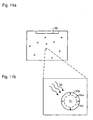
- Figure 11 illustrates a bubble removal means that benefits from a significantly enhanced bubble removal rate without undue influence on the immersion liquid.
- the improved removal rate is achieved by increasing the size of the bubbles in the immersion liquid by heating.
- the increased bubble size renders them more responsive to most methods of bubble removal. This is achieved without adverse heating effects in the immersion liquid, or surrounding temperature sensitive components, through the use of a microwave radiation source 30, producing radiation that couples only to the gas within the bubbles themselves and not to the immersion liquid itself.
- Figure 11a which shows a schematic magnified view of the immersion liquid, illustrating how the process operates. Microwave photons 32 are absorbed by an example bubble 31a at temperature T1, which is then heated to become a larger bubble 31b at temperature T2.
- the frequency components of the microwave radiation are chosen to correspond with resonant frequencies or excitation modes of species present in the bubbles.
- a large fraction of the gas forming the bubbles will be nitrogen and oxygen, in which case the resonant modes of these molecules will dictate the microwave frequencies to use.
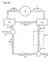
- Figure 12 illustrates an alternative bubble removal means.
- a particle input device 33 introduces into the immersion liquid particles that act to attract bubbles to their surface.
- the particles may be mixed with the immersion liquid either by natural dispersion or deliberate agitation.
- the particles may be left in the immersion liquid for a period determined according to the concentration of bubbles. For example, if the bubble concentration is very high, the particles will become saturated quickly and will need to be refreshed after a relatively short time. If, on the other hand, the bubble concentration is low, the particles may remain active for a much longer time.
- the particles may be removed from the liquid by a particle removal device 34, which may comprise for example a particle filter.
- the particle input device 33 and particle removal device 34 are coupled to the channels 23 for circulating the immersion liquid through the region 36 through a circuit indicated by the arrows 37 and 38.
- the circuit in question may be closed, as indicated by arrows 38, or involve input and output to a mains, or other, water supply as indicated by arrows 37.
- the used particles may be treated in a particle recycling device 35 to remove the gas bubbles from the particles. This de-gassing process may be achieved, for example, by pumping on a solution containing the particles or by pumping directly on the particles themselves.
- the clean particles may then be reintroduced to the immersion liquid via the particle input device 33 where they will again act effectively to trap bubbles.
- the particles are arranged to have surface characteristics that encourage bubbles to attach to the surface, for example in order to lower their surface energy.
- this parameter may be varied by controlling the size and number distribution, and porosity of the particles. A balance may need to be achieved in pore size because although finer pores may provide the greatest additional surface area, they will exclude bubbles that are of a similar order of size or that are large in comparison with the pores (the pores may also be blocked by such bubbles).
- particle compositions for example silica, zeolites, alumina, activated carbon, or a carbon molecular sieve. Certain polymer compositions may also be used.
- the particle size is a less critical factor (compared with the surface area) and a typical size range may be 5 to 1000 ⁇ m diameter.
- the particle input device 33 and the particle removal device 34 are both located outside of the region 36. However, these components may also be arranged to add and remove particles directly within this region.
- An alternative method for bringing the particles into the liquid is the occasional use of ultrasonic agitation in combination with non-degassed liquid. Due to cavitation of the bubbles, particles will be released from solid surfaces exposed to the liquid.
- Figure 13 shows a schematic representation of a section of the lithographic projection apparatus between the mask MA and the substrate W.
- This diagram shows several possible examples wherein either the bubble detection means or a detection system is arranged to propagate light between a light source 39 and a detector 40.
- the presence of bubbles (in the case of the bubble detection system) or particles (in the case of the detection system) is established via an increase or decrease in the intensity of light reaching the detector 40, caused by light scattering from bubbles or particles within the liquid.
- Figure 13 shows one possible arrangement, with the light source 39 arranged via an optical fibre 41 to direct light rays into the immersion liquid. Light propagates through the liquid and, if bubbles or particles are present, may scatter from them.
- FIG. 14 and 15 show magnified views of the substrate region showing how the light is fed into the immersion liquid.
- the optical fibre 41 is fed through the seal member 17 and makes its way into the region 36 either directly or after a number of reflections.
- Figure 15 shows an alternative arrangement whereby light is introduced between the substrate W and the seal member 17.
- light is shown (by arrows 43a and 43b) entering from a single direction and traversing the region 36 horizontally.
- light may be fed into the liquid from any direction and take various paths including paths comprising one or more reflections off the final element of the projection system PL and/or the substrate W.
- the signal strength detected at the light detector will increase as the concentration of bubbles or particles in the liquid increases due to the overall increase in scattering.
- the light source 39 and detector 40 may be arranged so that increased scattering leads to a decrease in the signal strength arriving at the detector 40.
- the optical fibre 41 may connect to both an illumination source and detector, the presence of bubbles or particles being detected by a change in the amount of light being reflected back into the optical fibre 41.
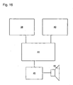
- Figure 16 illustrates schematically how the arrangement may be realised, with the light source 39 and detector 40 interacting with a light comparator 44.
- the light comparator 44 compares the light emitted by the light source 39 and the signal level arriving at the detector 40, and, depending on the arrangement of source and detector, determines information about the population of bubbles or particles present in the immersion liquid.
- the light comparator 44 may interact with a liquid quality monitor 45, which may be realised by a suitably programmed computer.
- the liquid quality monitor 45 may be arranged to ensure that the liquid is always at a suitable level of cleanliness to ensure that the quality of the image being written to the substrate W does not fall below a minimum threshold level.
- the liquid quality monitor 45 may take into account, in addition to the concentration of bubbles or particles, other factors such as the chemical composition of the liquid.
- the liquid quality monitor 45 may in turn be coupled to an alarm system 46 that causes the system to be shut down from an active state to a suspended state, or other appropriate action to be taken, when the state of the immersion liquid falls outside predefined parameters. This early reaction to problems in the liquid allows corrective action to be taken promptly, and also minimises the loss of materials and time associated with substandard exposures caused by low quality immersion liquid.
- the imaging performance of the lithography system may also be affected negatively (causing stray light, for example) by contamination on the bottom part of the lens PL.
- contamination may include, for example, the formation of salts arising primarily from the resist chemicals or oxides such as SiO 2 .
- the contamination may be reduced by mechanical or chemical cleaning, but such procedures involve expensive stoppages and service man hours, are not always completely effective and risk damage to the lens.
- one or more ultrasonic transducers are provided to detect or remove bubbles from the immersion liquid. These devices may also be oriented and configured to remove contamination from the final element of the projection lens PL and the substrate or wafer chuck W.
- FIG 17 shows one possible arrangement, wherein ultrasonic transducers 47 are located on the seal member 17 and may couple directly to the liquid between the final element of the projection lens PL and the substrate W.
- the transducers 47 may be mechanically isolated from, or at least in damped connection with, the seal member 17.
- the transducers 47 may be located nearby, rather than on, the seal member 17.
- the device connection to the lens PL may be mechanically released when the high frequency is generated.
- a wide variety of high frequency generators may be used that produce ultrasonic waves resonant with the immersion liquid.
- the ultrasonic lens and wafer chuck cleaning action may be implemented automatically and be arranged to cycle on and off according to the rate of contamination.
Landscapes
- Physics & Mathematics (AREA)
- General Physics & Mathematics (AREA)
- Health & Medical Sciences (AREA)
- Public Health (AREA)
- Engineering & Computer Science (AREA)
- Environmental & Geological Engineering (AREA)
- Epidemiology (AREA)
- Atmospheric Sciences (AREA)
- Toxicology (AREA)
- Life Sciences & Earth Sciences (AREA)
- Exposure And Positioning Against Photoresist Photosensitive Materials (AREA)
- Exposure Of Semiconductors, Excluding Electron Or Ion Beam Exposure (AREA)
- Degasification And Air Bubble Elimination (AREA)
Claims (19)
- Ein lithographisches Projektionsgerät, das Folgendes beinhaltet:- ein Beleuchtungssystem (IL), das eingerichtet ist, um einen Strahlungsstrahl (PB) bereitzustellen;- eine Stützstruktur (MT), die konfiguriert ist, um eine Musteraufbringungsvorrichtung (MA) zu stützen, wobei die Musteraufbringungsvorrichtung (MA) in der Lage ist, den Strahlungsstrahl (PB) in seinem Querschnitt mit einem Muster zu versehen, wodurch ein gemusterter Strahlungsstrahl bereitgestellt wird;- einen Substrattisch (WT), der konfiguriert ist, um ein Substrat (W) zu halten;- ein Projektionssystem (PL), das eingerichtet ist, um den gemusterten Strahlungsstrahl auf einen Zielabschnitt des Substrats (W) zu projizieren;- ein Flüssigkeitszufuhrsystem (1), das konfiguriert ist, um einen Raum zwischen einem Endelement des Projektionssystems (PL) und dem Substrat (W) mindestens teilweise mit Flüssigkeit zu füllen, wobei
das Flüssigkeitszufuhrsystem (1) ein Blasenreduzierungsmittel (3a, 3b) beinhaltet und das Blasenreduzierungsmittel (3a, 3b) ein Blasendetektionsmittel (4) beinhaltet, dadurch gekennzeichnet, dass das Blasendetektionsmittel (4) mindestens einen Ultraschallwandler (5a, 5b) beinhaltet, der eingerichtet ist, um die Abschwächung von Ultraschallwellen in der Flüssigkeit zu messen, um Informationen über in der Flüssigkeit vorhandene Blasen zu erhalten. - Lithographisches Projektionsgerät gemäß Anspruch 1, wobei der Ultraschallwandler (5a, 5b) Ultraschallabschwächung als eine Funktion der Frequenz misst.
- Lithographisches Projektionsgerät gemäß Anspruch 1 oder 2, wobei das Blasenreduzierungsmittel (3a, 3b) ein Blasenentfernungsmittel beinhaltet.
- Lithographisches Projektionsgerät gemäß Anspruch 3, wobei das Blasenentfernungsmittel eine Entgasungsvorrichtung (10) beinhaltet, wobei die Entgasungsvorrichtung (10) eine lsolationskammer (11) beinhaltet, wobei ein Raum über einer Flüssigkeit in der lsolationskammer (11) auf einem Druck unter dem atmosphärischem Druck beibehalten wird, was zuvor aufgelöste Gase darin unterstützt, aus der Lösung auszutreten und abgepumpt zu werden.
- Lithographisches Projektionsgerät gemäß Anspruch 3 oder 4, wobei das Blasenentfernungsmittel eine kontinuierliche Strömung von Flüssigkeit über das Endelement des Projektionssystems (PL) und das Substrat (W) bereitstellt, um Blasen in der Flüssigkeit aus dem Raum zwischen dem Endelement des Projektionssystems (PL) und dem Substrat (W) heraus zu transportieren.
- Lithographisches Projektionsgerät gemäß einem der vorhergehenden Ansprüche, wobei das Blasenreduzierungsmittel (3a, 3b) eine Flüssigkeitdruckbeaufschlagungs-Vorrichtung (22) beinhaltet, um die Flüssigkeit über den atmosphärischen Druck hinaus mit Druck zu beaufschlagen, um die Größe der Blasen zu minimieren und Blasen bildende Gase darin zu unterstützen, sich in der Flüssigkeit aufzulösen.
- Lithographisches Projektionsgerät gemäß einem der vorhergehenden Ansprüche, wobei die Zusammensetzung der Flüssigkeit so gewählt ist, dass sie eine geringere Oberflächenspannung als Wasser aufweist.
- Lithographisches Projektionsgerät gemäß einem der vorhergehenden Ansprüche, wobei das Blasenreduzierungsmittel (3a, 3b) die Flüssigkeit aufbereitet, bevor sie dem Raum zwischen dem Endelement des Projektionssystems (PL) und dem Substrat (W) zugeführt wird.
- Lithographisches Projektionsgerät gemäß Anspruch 8, wobei die aufbereitete Flüssigkeit in einem abgedichteten Behälter aufbewahrt wird, wobei überschüssiger Raum in dem abgedichteten Behälter mit einem oder mehreren der Folgenden gefüllt ist: Stickstoffgas, Argongas, Heliumgas oder einem Vakuum.
- Lithographisches Projektionsgerät gemäß Anspruch 1 oder 2, wobei ein Ultraschallwandler (5a) in einer Impuls-Echo-Konfiguration eingerichtet ist, wobei der Wandler (5a) wirkt, um sowohl Ultraschallwellen zu senden als auch Ultraschallwellen, die während der Ausbreitung entlang einem Weg durch die Flüssigkeit abgeschwächt worden sind, nach Reflexion zu empfangen.
- Lithographisches Projektionsgerät gemäß Anspruch 1 oder 2, wobei das Blasendetektionsmittel (4) zwei räumlich getrennte Ultraschallwandler (5b) beinhaltet, wobei der erste eingerichtet ist, um Ultraschallwellen zu senden, und der zweite, um Ultraschallwellen zu empfangen, die während der Ausbreitung entlang einem Weg durch die Flüssigkeit zwischen den zwei Wandlern (5b) abgeschwächt worden sind.
- Lithographisches Projektionsgerät gemäß Anspruch 3, 4 oder 5, wobei das Blasenentfernungsmittel zwei räumlich getrennte Ultraschallwandler (5c) umfasst, die eingerichtet sind, um innerhalb der Flüssigkeit stehende Ultraschallwellenmuster, die Blasen innerhalb der Knotenbereiche fangen, zu produzieren, wobei das Blasenentfernungsmittel eingerichtet ist, um die Blasen durch die Verwendung eines Phaseneinstellungsmittels (8), das mit den Wandlern (5c) gekoppelt ist, zu verdrängen, wobei das Phaseneinstellungsmittel (8) eine räumliche Verschiebung der Knotenbereiche und der darin gefangenen Blasen bewirkt.
- Lithographisches Projektionsgerät gemäß Anspruch 3, 4, 5 oder 12, wobei das Blasenentfernungsmittel einen ein elektrisches Feld erzeugenden Generator (28) zum Anlegen eines elektrischen Feldes an die Flüssigkeit beinhaltet, wobei das elektrische Feld in der Lage ist, an dem Substrat haftende Blasen zu verdrängen.
- Lithographisches Projektionsgerät gemäß Anspruch 3, 4, 5, 12 oder 13, wobei das Blasenentfernungsmittel eine selektive Heizeinrichtung zum selektiven Steuern der Temperatur und daher der Größe der Blasen einer bestimmten Zusammensetzung beinhaltet.
- Lithographisches Projektionsgerät gemäß Anspruch 14, wobei die selektive Heizeinrichtung eine Mikrowellenquelle (30) beinhaltet.
- Lithographisches Projektionsgerät gemäß Anspruch 3, 4, 5, 12, 13 oder 14, wobei das Blasenentfernungsmittel eine Teilcheneingabevorrichtung (33) zum Einführen von Teilchen in die Flüssigkeit und eine Teilchenentfernungsvorrichtung (34) zum Entfernen von Teilchen aus der Flüssigkeit beinhaltet.
- Lithographisches Projektionsgerät gemäß Anspruch 16, wobei die Teilchen eine Oberfläche mit Eigenschaften, die Blasen darin unterstützen, daran zu haften, beinhalten.
- Lithographisches Projektionsgerät gemäß einem der vorhergehenden Ansprüche, wobei das Blasendetektionsmittel (4) eine Lichtquelle (39), einen Lichtdetektor (40) und einen Lichtvergleicher (44) beinhaltet, wobei die Lichtquelle (39) und der Lichtdetektor (40) so eingerichtet sind, dass sich von der Quelle (39) emittiertes Licht zwischen der Quelle (39) und dem Detektor (40) durch einen Teil der Flüssigkeit ausbreitet, wobei der Vergleicher (44) eingerichtet ist, um das von der Lichtquelle (39) emittierte Licht und den an dem Detektor (40) eintreffenden Signalpegel zu vergleichen, um Änderungen des Anteils des emittierten Lichts, der nach der Ausbreitung durch einen Teil der Flüssigkeit an dem Detektor (40) eintrifft, zu detektieren.
- Ein Verfahren zum Herstellen einer Vorrichtung, das die folgenden Schritte beinhaltet:- Bereitstellen eines Substrats (W), das mindestens teilweise mit einer Schicht aus strahlungsempfindlichem Material überzogen ist;- Bereitstellen eines Strahlungsstrahls (PB) unter Verwendung eines Beleuchtungssystems (IL);- Verwenden einer Musteraufbringungsvorrichtung (MA), um den Strahlungsstrahl (PB) in seinem Querschnitt mit einem Muster zu versehen, wodurch ein gemusterter Strahlungsstrahl bereitgestellt wird;- Projizieren des gemusterten Strahlungsstrahls auf einen Zielabschnitt der Schicht aus strahlungsempfindlichem Material;- Bereitstellen eines Flüssigkeitszufuhrsystems (1), das konfiguriert ist, um einen Raum zwischen dem Endelement des Projektionssystems (PL) und dem Substrat (W) mindestens teilweise mit Flüssigkeit zu füllen, und- Detektieren und Reduzieren von Blasen in dem Flüssigkeitszufuhrsystem (1); dadurch gekennzeichnet, dass:- der Detektierschritt das Verwenden mindestens eines Ultraschallwandlers (5a, 5b) zum Messen der Abschwächung von Ultraschallwellen in der Flüssigkeit beinhaltet.
Priority Applications (3)
| Application Number | Priority Date | Filing Date | Title |
|---|---|---|---|
| EP10179593A EP2261742A3 (de) | 2003-06-11 | 2004-06-04 | Lithographischer Apparat und Verfahren zur Herstellung einer Vorrichtung |
| EP10179589A EP2261741A3 (de) | 2003-06-11 | 2004-06-04 | Lithographischer Apparat und Verfahren zur Herstellung einer Vorrichtung |
| EP04253325A EP1486827B1 (de) | 2003-06-11 | 2004-06-04 | Lithographischer Apparat und Verfahren zur Herstellung einer Vorrichtung |
Applications Claiming Priority (5)
| Application Number | Priority Date | Filing Date | Title |
|---|---|---|---|
| US820227 | 1997-03-18 | ||
| EP03253694 | 2003-06-11 | ||
| EP03253694A EP1489461A1 (de) | 2003-06-11 | 2003-06-11 | Lithographischer Apparat und Verfahren zur Herstellung einer Vorrichtung |
| US10/820,227 US7317504B2 (en) | 2004-04-08 | 2004-04-08 | Lithographic apparatus and device manufacturing method |
| EP04253325A EP1486827B1 (de) | 2003-06-11 | 2004-06-04 | Lithographischer Apparat und Verfahren zur Herstellung einer Vorrichtung |
Related Child Applications (2)
| Application Number | Title | Priority Date | Filing Date |
|---|---|---|---|
| EP10179593.8 Division-Into | 2010-09-24 | ||
| EP10179589.6 Division-Into | 2010-09-24 |
Publications (3)
| Publication Number | Publication Date |
|---|---|
| EP1486827A2 EP1486827A2 (de) | 2004-12-15 |
| EP1486827A3 EP1486827A3 (de) | 2005-03-09 |
| EP1486827B1 true EP1486827B1 (de) | 2011-11-02 |
Family
ID=34105755
Family Applications (3)
| Application Number | Title | Priority Date | Filing Date |
|---|---|---|---|
| EP04253325A Expired - Lifetime EP1486827B1 (de) | 2003-06-11 | 2004-06-04 | Lithographischer Apparat und Verfahren zur Herstellung einer Vorrichtung |
| EP10179593A Withdrawn EP2261742A3 (de) | 2003-06-11 | 2004-06-04 | Lithographischer Apparat und Verfahren zur Herstellung einer Vorrichtung |
| EP10179589A Withdrawn EP2261741A3 (de) | 2003-06-11 | 2004-06-04 | Lithographischer Apparat und Verfahren zur Herstellung einer Vorrichtung |
Family Applications After (2)
| Application Number | Title | Priority Date | Filing Date |
|---|---|---|---|
| EP10179593A Withdrawn EP2261742A3 (de) | 2003-06-11 | 2004-06-04 | Lithographischer Apparat und Verfahren zur Herstellung einer Vorrichtung |
| EP10179589A Withdrawn EP2261741A3 (de) | 2003-06-11 | 2004-06-04 | Lithographischer Apparat und Verfahren zur Herstellung einer Vorrichtung |
Country Status (7)
| Country | Link |
|---|---|
| US (5) | US7684008B2 (de) |
| EP (3) | EP1486827B1 (de) |
| JP (4) | JP4199700B2 (de) |
| KR (1) | KR100695987B1 (de) |
| CN (2) | CN102063018B (de) |
| SG (1) | SG118281A1 (de) |
| TW (1) | TWI253546B (de) |
Cited By (5)
| Publication number | Priority date | Publication date | Assignee | Title |
|---|---|---|---|---|
| US8115899B2 (en) | 2004-12-20 | 2012-02-14 | Asml Netherlands B.V. | Lithographic apparatus and device manufacturing method |
| US8629971B2 (en) | 2003-08-29 | 2014-01-14 | Asml Netherlands B.V. | Lithographic apparatus and device manufacturing method |
| US8654305B2 (en) | 2007-02-15 | 2014-02-18 | Asml Holding N.V. | Systems and methods for insitu lens cleaning in immersion lithography |
| US8817226B2 (en) | 2007-02-15 | 2014-08-26 | Asml Holding N.V. | Systems and methods for insitu lens cleaning using ozone in immersion lithography |
| TWI686679B (zh) * | 2012-12-27 | 2020-03-01 | 日商尼康股份有限公司 | 曝光裝置及元件製造方法 |
Families Citing this family (277)
| Publication number | Priority date | Publication date | Assignee | Title |
|---|---|---|---|---|
| US7019819B2 (en) * | 2002-11-13 | 2006-03-28 | Molecular Imprints, Inc. | Chucking system for modulating shapes of substrates |
| US7442336B2 (en) * | 2003-08-21 | 2008-10-28 | Molecular Imprints, Inc. | Capillary imprinting technique |
| US7077992B2 (en) * | 2002-07-11 | 2006-07-18 | Molecular Imprints, Inc. | Step and repeat imprint lithography processes |
| US7372541B2 (en) * | 2002-11-12 | 2008-05-13 | Asml Netherlands B.V. | Lithographic apparatus and device manufacturing method |
| US10503084B2 (en) | 2002-11-12 | 2019-12-10 | Asml Netherlands B.V. | Lithographic apparatus and device manufacturing method |
| SG135052A1 (en) * | 2002-11-12 | 2007-09-28 | Asml Netherlands Bv | Lithographic apparatus and device manufacturing method |
| SG121819A1 (en) | 2002-11-12 | 2006-05-26 | Asml Netherlands Bv | Lithographic apparatus and device manufacturing method |
| US9482966B2 (en) | 2002-11-12 | 2016-11-01 | Asml Netherlands B.V. | Lithographic apparatus and device manufacturing method |
| US7948604B2 (en) * | 2002-12-10 | 2011-05-24 | Nikon Corporation | Exposure apparatus and method for producing device |
| JP4352874B2 (ja) * | 2002-12-10 | 2009-10-28 | 株式会社ニコン | 露光装置及びデバイス製造方法 |
| DE10261775A1 (de) | 2002-12-20 | 2004-07-01 | Carl Zeiss Smt Ag | Vorrichtung zur optischen Vermessung eines Abbildungssystems |
| KR101643112B1 (ko) | 2003-02-26 | 2016-07-26 | 가부시키가이샤 니콘 | 노광 장치, 노광 방법 및 디바이스 제조 방법 |
| SG139733A1 (en) * | 2003-04-11 | 2008-02-29 | Nikon Corp | Apparatus having an immersion fluid system configured to maintain immersion fluid in a gap adjacent an optical assembly |
| KR101289959B1 (ko) * | 2003-04-11 | 2013-07-26 | 가부시키가이샤 니콘 | 액침 리소그래피에 의한 광학기기의 세정방법 |
| KR20050122269A (ko) * | 2003-04-17 | 2005-12-28 | 가부시키가이샤 니콘 | 액침 리소그래피를 이용하기 위한 오토포커스 소자의광학적 배열 |
| WO2004102646A1 (ja) * | 2003-05-15 | 2004-11-25 | Nikon Corporation | 露光装置及びデバイス製造方法 |
| TWI474380B (zh) * | 2003-05-23 | 2015-02-21 | 尼康股份有限公司 | A method of manufacturing an exposure apparatus and an element |
| TW201515064A (zh) | 2003-05-23 | 2015-04-16 | 尼康股份有限公司 | 曝光方法及曝光裝置以及元件製造方法 |
| WO2004107417A1 (ja) | 2003-05-28 | 2004-12-09 | Nikon Corporation | 露光方法及び露光装置、並びにデバイス製造方法 |
| US7213963B2 (en) | 2003-06-09 | 2007-05-08 | Asml Netherlands B.V. | Lithographic apparatus and device manufacturing method |
| US7317504B2 (en) * | 2004-04-08 | 2008-01-08 | Asml Netherlands B.V. | Lithographic apparatus and device manufacturing method |
| EP1486827B1 (de) | 2003-06-11 | 2011-11-02 | ASML Netherlands B.V. | Lithographischer Apparat und Verfahren zur Herstellung einer Vorrichtung |
| EP3104396B1 (de) | 2003-06-13 | 2018-03-21 | Nikon Corporation | Belichtungsverfahren, substrattisch, belichtungsvorrichtung und vorrichtungsherstellungsverfahren |
| US6867844B2 (en) | 2003-06-19 | 2005-03-15 | Asml Holding N.V. | Immersion photolithography system and method using microchannel nozzles |
| KR101476087B1 (ko) | 2003-06-19 | 2014-12-23 | 가부시키가이샤 니콘 | 노광 장치 및 디바이스 제조방법 |
| US6809794B1 (en) * | 2003-06-27 | 2004-10-26 | Asml Holding N.V. | Immersion photolithography system and method using inverted wafer-projection optics interface |
| WO2005006026A2 (en) * | 2003-07-01 | 2005-01-20 | Nikon Corporation | Using isotopically specified fluids as optical elements |
| EP2843472B1 (de) * | 2003-07-08 | 2016-12-07 | Nikon Corporation | Waferplatte für die Immersionslithografie |
| EP2264531B1 (de) * | 2003-07-09 | 2013-01-16 | Nikon Corporation | Belichtungsgerät und Verfahren zur Herstellung einer Vorrichtung |
| WO2005006418A1 (ja) * | 2003-07-09 | 2005-01-20 | Nikon Corporation | 露光装置及びデバイス製造方法 |
| EP1643543B1 (de) * | 2003-07-09 | 2010-11-24 | Nikon Corporation | Belichtungsvorrichtung und verfahren zur bauelementherstellung |
| US7738074B2 (en) * | 2003-07-16 | 2010-06-15 | Asml Netherlands B.V. | Lithographic apparatus and device manufacturing method |
| JP4524669B2 (ja) * | 2003-07-25 | 2010-08-18 | 株式会社ニコン | 投影光学系の検査方法および検査装置 |
| US7006209B2 (en) | 2003-07-25 | 2006-02-28 | Advanced Micro Devices, Inc. | Method and apparatus for monitoring and controlling imaging in immersion lithography systems |
| US7175968B2 (en) * | 2003-07-28 | 2007-02-13 | Asml Netherlands B.V. | Lithographic apparatus, device manufacturing method and a substrate |
| EP1503244A1 (de) | 2003-07-28 | 2005-02-02 | ASML Netherlands B.V. | Lithographischer Projektionsapparat und Verfahren zur Herstellung einer Vorrichtung |
| KR20190002749A (ko) * | 2003-07-28 | 2019-01-08 | 가부시키가이샤 니콘 | 노광 장치 및 디바이스 제조 방법, 그리고 노광 장치의 제어 방법 |
| US7779781B2 (en) * | 2003-07-31 | 2010-08-24 | Asml Netherlands B.V. | Lithographic apparatus and device manufacturing method |
| US7370659B2 (en) * | 2003-08-06 | 2008-05-13 | Micron Technology, Inc. | Photolithographic stepper and/or scanner machines including cleaning devices and methods of cleaning photolithographic stepper and/or scanner machines |
| US7061578B2 (en) * | 2003-08-11 | 2006-06-13 | Advanced Micro Devices, Inc. | Method and apparatus for monitoring and controlling imaging in immersion lithography systems |
| KR101419192B1 (ko) * | 2003-08-29 | 2014-07-15 | 가부시키가이샤 니콘 | 노광 장치 및 디바이스 제조 방법 |
| TWI263859B (en) | 2003-08-29 | 2006-10-11 | Asml Netherlands Bv | Lithographic apparatus and device manufacturing method |
| US7014966B2 (en) | 2003-09-02 | 2006-03-21 | Advanced Micro Devices, Inc. | Method and apparatus for elimination of bubbles in immersion medium in immersion lithography systems |
| EP1660925B1 (de) | 2003-09-03 | 2015-04-29 | Nikon Corporation | Vorrichtung und verfahren zur bereitstellung eines fluids für die immersionslithographie |
| JP4444920B2 (ja) * | 2003-09-19 | 2010-03-31 | 株式会社ニコン | 露光装置及びデバイス製造方法 |
| KR101301804B1 (ko) * | 2003-09-26 | 2013-08-29 | 가부시키가이샤 니콘 | 투영노광장치 및 투영노광장치의 세정방법, 메인터넌스 방법 그리고 디바이스의 제조방법 |
| KR101498437B1 (ko) * | 2003-09-29 | 2015-03-03 | 가부시키가이샤 니콘 | 노광장치, 노광방법 및 디바이스 제조방법 |
| EP1672681B8 (de) | 2003-10-08 | 2011-09-21 | Miyagi Nikon Precision Co., Ltd. | Belichtungsgerät, substrattrageverfahren, belichtungsverfahren und verfahren zur herstellung einer vorrichtung |
| KR20060126949A (ko) | 2003-10-08 | 2006-12-11 | 가부시키가이샤 니콘 | 기판 반송 장치와 기판 반송 방법, 노광 장치와 노광 방법,및 디바이스 제조 방법 |
| JP2005136364A (ja) * | 2003-10-08 | 2005-05-26 | Zao Nikon Co Ltd | 基板搬送装置、露光装置、並びにデバイス製造方法 |
| TW200514138A (en) | 2003-10-09 | 2005-04-16 | Nippon Kogaku Kk | Exposure equipment and exposure method, manufacture method of component |
| US7411653B2 (en) * | 2003-10-28 | 2008-08-12 | Asml Netherlands B.V. | Lithographic apparatus |
| US7528929B2 (en) * | 2003-11-14 | 2009-05-05 | Asml Netherlands B.V. | Lithographic apparatus and device manufacturing method |
| EP3370115A1 (de) * | 2003-12-03 | 2018-09-05 | Nikon Corporation | Belichtungsvorrichtung, belichtungsverfahren, und verfahren zur herstellung eines artikels |
| JPWO2005057635A1 (ja) * | 2003-12-15 | 2007-07-05 | 株式会社ニコン | 投影露光装置及びステージ装置、並びに露光方法 |
| KR101281397B1 (ko) | 2003-12-15 | 2013-07-02 | 가부시키가이샤 니콘 | 스테이지 장치, 노광 장치, 및 노광 방법 |
| US20070081133A1 (en) * | 2004-12-14 | 2007-04-12 | Niikon Corporation | Projection exposure apparatus and stage unit, and exposure method |
| EP1700163A1 (de) | 2003-12-15 | 2006-09-13 | Carl Zeiss SMT AG | Objektiv als mikrolithographie-projektionsobjektiv mit mindestens einer flüssigen linse |
| JP4323946B2 (ja) * | 2003-12-19 | 2009-09-02 | キヤノン株式会社 | 露光装置 |
| CN1938646B (zh) * | 2004-01-20 | 2010-12-15 | 卡尔蔡司Smt股份公司 | 曝光装置和用于投影透镜的测量装置 |
| JP4319189B2 (ja) * | 2004-01-26 | 2009-08-26 | 株式会社ニコン | 露光装置及びデバイス製造方法 |
| US7589822B2 (en) * | 2004-02-02 | 2009-09-15 | Nikon Corporation | Stage drive method and stage unit, exposure apparatus, and device manufacturing method |
| JP4506674B2 (ja) * | 2004-02-03 | 2010-07-21 | 株式会社ニコン | 露光装置及びデバイス製造方法 |
| US7050146B2 (en) | 2004-02-09 | 2006-05-23 | Asml Netherlands B.V. | Lithographic apparatus and device manufacturing method |
| CN101727021A (zh) * | 2004-02-13 | 2010-06-09 | 卡尔蔡司Smt股份公司 | 微平版印刷投影曝光装置的投影物镜 |
| CN100592210C (zh) | 2004-02-13 | 2010-02-24 | 卡尔蔡司Smt股份公司 | 微平版印刷投影曝光装置的投影物镜 |
| US20070030467A1 (en) * | 2004-02-19 | 2007-02-08 | Nikon Corporation | Exposure apparatus, exposure method, and device fabricating method |
| US20080151200A1 (en) * | 2004-02-19 | 2008-06-26 | Nikon Corporation | Exposure Apparatus and Device Manufacturing Method |
| CN100524616C (zh) * | 2004-02-19 | 2009-08-05 | 株式会社尼康 | 曝光装置、曝光方法以及元件制造方法 |
| WO2005081292A1 (ja) * | 2004-02-20 | 2005-09-01 | Nikon Corporation | 露光装置、供給方法及び回収方法、露光方法、ならびにデバイス製造方法 |
| US7034917B2 (en) * | 2004-04-01 | 2006-04-25 | Asml Netherlands B.V. | Lithographic apparatus, device manufacturing method and device manufactured thereby |
| US7898642B2 (en) | 2004-04-14 | 2011-03-01 | Asml Netherlands B.V. | Lithographic apparatus and device manufacturing method |
| EP1747499A2 (de) * | 2004-05-04 | 2007-01-31 | Nikon Corporation | Vorrichtung und verfahren zur bereitstellung eines fluids für die immersionslithographie |
| US20060244938A1 (en) * | 2004-05-04 | 2006-11-02 | Karl-Heinz Schuster | Microlitographic projection exposure apparatus and immersion liquid therefore |
| JP3981368B2 (ja) * | 2004-05-17 | 2007-09-26 | 松下電器産業株式会社 | パターン形成方法 |
| US7616383B2 (en) | 2004-05-18 | 2009-11-10 | Asml Netherlands B.V. | Lithographic apparatus and device manufacturing method |
| US7486381B2 (en) * | 2004-05-21 | 2009-02-03 | Asml Netherlands B.V. | Lithographic apparatus and device manufacturing method |
| CN100594430C (zh) | 2004-06-04 | 2010-03-17 | 卡尔蔡司Smt股份公司 | 用于测量光学成像系统的图像质量的系统 |
| KR101421915B1 (ko) * | 2004-06-09 | 2014-07-22 | 가부시키가이샤 니콘 | 노광 장치 및 디바이스 제조 방법 |
| US8717533B2 (en) | 2004-06-10 | 2014-05-06 | Nikon Corporation | Exposure apparatus, exposure method, and method for producing device |
| JP4515335B2 (ja) * | 2004-06-10 | 2010-07-28 | 株式会社ニコン | 露光装置、ノズル部材、及びデバイス製造方法 |
| EP2624282B1 (de) * | 2004-06-10 | 2017-02-08 | Nikon Corporation | Immersionsbelichtungsvorrichtung und -verfahren, und Verfahren zur Herstellung eines Geräts |
| US8508713B2 (en) | 2004-06-10 | 2013-08-13 | Nikon Corporation | Exposure apparatus, exposure method, and method for producing device |
| US8373843B2 (en) | 2004-06-10 | 2013-02-12 | Nikon Corporation | Exposure apparatus, exposure method, and method for producing device |
| US7481867B2 (en) * | 2004-06-16 | 2009-01-27 | Edwards Limited | Vacuum system for immersion photolithography |
| US8698998B2 (en) | 2004-06-21 | 2014-04-15 | Nikon Corporation | Exposure apparatus, method for cleaning member thereof, maintenance method for exposure apparatus, maintenance device, and method for producing device |
| US20090225286A1 (en) * | 2004-06-21 | 2009-09-10 | Nikon Corporation | Exposure apparatus, method for cleaning member thereof , maintenance method for exposure apparatus, maintenance device, and method for producing device |
| JP4677833B2 (ja) * | 2004-06-21 | 2011-04-27 | 株式会社ニコン | 露光装置、及びその部材の洗浄方法、露光装置のメンテナンス方法、メンテナンス機器、並びにデバイス製造方法 |
| US7463330B2 (en) | 2004-07-07 | 2008-12-09 | Asml Netherlands B.V. | Lithographic apparatus and device manufacturing method |
| EP1780772B1 (de) * | 2004-07-12 | 2009-09-02 | Nikon Corporation | Belichtungsgerät und bauelemente-herstellungsverfahren |
| JP4752375B2 (ja) * | 2004-08-03 | 2011-08-17 | 株式会社ニコン | 露光装置、露光方法及びデバイス製造方法 |
| US7224427B2 (en) | 2004-08-03 | 2007-05-29 | Taiwan Semiconductor Manufacturing Company, Ltd. | Megasonic immersion lithography exposure apparatus and method |
| KR101230712B1 (ko) * | 2004-08-03 | 2013-02-07 | 가부시키가이샤 니콘 | 노광 장치, 노광 방법 및 디바이스 제조 방법 |
| US8305553B2 (en) * | 2004-08-18 | 2012-11-06 | Nikon Corporation | Exposure apparatus and device manufacturing method |
| US7701550B2 (en) * | 2004-08-19 | 2010-04-20 | Asml Netherlands B.V. | Lithographic apparatus and device manufacturing method |
| US20060044533A1 (en) * | 2004-08-27 | 2006-03-02 | Asmlholding N.V. | System and method for reducing disturbances caused by movement in an immersion lithography system |
| US7385670B2 (en) * | 2004-10-05 | 2008-06-10 | Asml Netherlands B.V. | Lithographic apparatus, cleaning system and cleaning method for in situ removing contamination from a component in a lithographic apparatus |
| US7379155B2 (en) | 2004-10-18 | 2008-05-27 | Asml Netherlands B.V. | Lithographic apparatus and device manufacturing method |
| US7414699B2 (en) * | 2004-11-12 | 2008-08-19 | Asml Netherlands B.V. | Lithographic apparatus and device manufacturing method |
| US7411657B2 (en) | 2004-11-17 | 2008-08-12 | Asml Netherlands B.V. | Lithographic apparatus and device manufacturing method |
| US7119035B2 (en) * | 2004-11-22 | 2006-10-10 | Taiwan Semiconductor Manufacturing Company, Ltd. | Method using specific contact angle for immersion lithography |
| US7732123B2 (en) * | 2004-11-23 | 2010-06-08 | Taiwan Semiconductor Manufacturing Company, Ltd. | Immersion photolithography with megasonic rinse |
| US7623218B2 (en) * | 2004-11-24 | 2009-11-24 | Carl Zeiss Smt Ag | Method of manufacturing a miniaturized device |
| US7256121B2 (en) * | 2004-12-02 | 2007-08-14 | Texas Instruments Incorporated | Contact resistance reduction by new barrier stack process |
| US7446850B2 (en) * | 2004-12-03 | 2008-11-04 | Asml Netherlands B.V. | Lithographic apparatus and device manufacturing method |
| JP4784513B2 (ja) * | 2004-12-06 | 2011-10-05 | 株式会社ニコン | メンテナンス方法、メンテナンス機器、露光装置、及びデバイス製造方法 |
| US7196770B2 (en) * | 2004-12-07 | 2007-03-27 | Asml Netherlands B.V. | Prewetting of substrate before immersion exposure |
| US7397533B2 (en) * | 2004-12-07 | 2008-07-08 | Asml Netherlands B.V. | Lithographic apparatus and device manufacturing method |
| US7365827B2 (en) | 2004-12-08 | 2008-04-29 | Asml Netherlands B.V. | Lithographic apparatus and device manufacturing method |
| JP4752473B2 (ja) | 2004-12-09 | 2011-08-17 | 株式会社ニコン | 露光装置、露光方法及びデバイス製造方法 |
| US7352440B2 (en) | 2004-12-10 | 2008-04-01 | Asml Netherlands B.V. | Substrate placement in immersion lithography |
| US7403261B2 (en) * | 2004-12-15 | 2008-07-22 | Asml Netherlands B.V. | Lithographic apparatus and device manufacturing method |
| US7528931B2 (en) * | 2004-12-20 | 2009-05-05 | Asml Netherlands B.V. | Lithographic apparatus and device manufacturing method |
| US7491661B2 (en) * | 2004-12-28 | 2009-02-17 | Asml Netherlands B.V. | Device manufacturing method, top coat material and substrate |
| US7405805B2 (en) | 2004-12-28 | 2008-07-29 | Asml Netherlands B.V. | Lithographic apparatus and device manufacturing method |
| US20060147821A1 (en) | 2004-12-30 | 2006-07-06 | Asml Netherlands B.V. | Lithographic apparatus and device manufacturing method |
| US7450217B2 (en) | 2005-01-12 | 2008-11-11 | Asml Netherlands B.V. | Exposure apparatus, coatings for exposure apparatus, lithographic apparatus, device manufacturing method, and device manufactured thereby |
| DE602006012746D1 (de) * | 2005-01-14 | 2010-04-22 | Asml Netherlands Bv | Lithografische Vorrichtung und Herstellungsverfahren |
| SG124351A1 (en) | 2005-01-14 | 2006-08-30 | Asml Netherlands Bv | Lithographic apparatus and device manufacturing method |
| JPWO2006080250A1 (ja) * | 2005-01-25 | 2008-08-07 | Jsr株式会社 | 液浸型露光システム、液浸型露光用液体のリサイクル方法及び供給方法 |
| KR101236023B1 (ko) * | 2005-01-28 | 2013-02-21 | 가부시키가이샤 니콘 | 투영 광학계, 노광 장치 및 노광 방법 |
| US7710653B2 (en) | 2005-01-28 | 2010-05-04 | Nikon Corporation | Projection optical system, exposure system, and exposure method |
| KR20180125636A (ko) | 2005-01-31 | 2018-11-23 | 가부시키가이샤 니콘 | 노광 장치 및 디바이스 제조 방법 |
| US8692973B2 (en) * | 2005-01-31 | 2014-04-08 | Nikon Corporation | Exposure apparatus and method for producing device |
| JP5162254B2 (ja) | 2005-02-10 | 2013-03-13 | エーエスエムエル ネザーランズ ビー.ブイ. | 液浸リソグラフィシステム及びデバイス製造方法 |
| US20070258068A1 (en) * | 2005-02-17 | 2007-11-08 | Hiroto Horikawa | Exposure Apparatus, Exposure Method, and Device Fabricating Method |
| US7378025B2 (en) | 2005-02-22 | 2008-05-27 | Asml Netherlands B.V. | Fluid filtration method, fluid filtered thereby, lithographic apparatus and device manufacturing method |
| US8018573B2 (en) * | 2005-02-22 | 2011-09-13 | Asml Netherlands B.V. | Lithographic apparatus and device manufacturing method |
| US7224431B2 (en) * | 2005-02-22 | 2007-05-29 | Asml Netherlands B.V. | Lithographic apparatus and device manufacturing method |
| US7864437B2 (en) * | 2005-02-28 | 2011-01-04 | Nikon Corporation | Adaptor for microscope and microscope apparatus (microscope-use adaptor and microscope device) |
| US7428038B2 (en) | 2005-02-28 | 2008-09-23 | Asml Netherlands B.V. | Lithographic apparatus, device manufacturing method and apparatus for de-gassing a liquid |
| US7282701B2 (en) | 2005-02-28 | 2007-10-16 | Asml Netherlands B.V. | Sensor for use in a lithographic apparatus |
| US7324185B2 (en) * | 2005-03-04 | 2008-01-29 | Asml Netherlands B.V. | Lithographic apparatus and device manufacturing method |
| US7684010B2 (en) * | 2005-03-09 | 2010-03-23 | Asml Netherlands B.V. | Lithographic apparatus, device manufacturing method, seal structure, method of removing an object and a method of sealing |
| US7330238B2 (en) * | 2005-03-28 | 2008-02-12 | Asml Netherlands, B.V. | Lithographic apparatus, immersion projection apparatus and device manufacturing method |
| JP2006310827A (ja) * | 2005-03-31 | 2006-11-09 | Nikon Corp | 露光装置、露光方法、及びデバイス製造方法 |
| TW200644079A (en) * | 2005-03-31 | 2006-12-16 | Nikon Corp | Exposure apparatus, exposure method, and device production method |
| US7411654B2 (en) * | 2005-04-05 | 2008-08-12 | Asml Netherlands B.V. | Lithographic apparatus and device manufacturing method |
| US7291850B2 (en) * | 2005-04-08 | 2007-11-06 | Asml Netherlands B.V. | Lithographic apparatus and device manufacturing method |
| US7515281B2 (en) | 2005-04-08 | 2009-04-07 | Asml Netherlands B.V. | Lithographic apparatus and device manufacturing method |
| US7161659B2 (en) | 2005-04-08 | 2007-01-09 | Asml Netherlands B.V. | Dual stage lithographic apparatus and device manufacturing method |
| USRE43576E1 (en) | 2005-04-08 | 2012-08-14 | Asml Netherlands B.V. | Dual stage lithographic apparatus and device manufacturing method |
| US20060232753A1 (en) * | 2005-04-19 | 2006-10-19 | Asml Holding N.V. | Liquid immersion lithography system with tilted liquid flow |
| KR101396620B1 (ko) | 2005-04-25 | 2014-05-16 | 가부시키가이샤 니콘 | 노광 방법, 노광 장치, 및 디바이스 제조 방법 |
| KR20080005376A (ko) * | 2005-04-28 | 2008-01-11 | 가부시키가이샤 니콘 | 노광 방법 및 노광 장치, 그리고 디바이스 제조 방법 |
| US7433016B2 (en) * | 2005-05-03 | 2008-10-07 | Asml Netherlands B.V. | Lithographic apparatus and device manufacturing method |
| US7317507B2 (en) * | 2005-05-03 | 2008-01-08 | Asml Netherlands B.V. | Lithographic apparatus and device manufacturing method |
| US8248577B2 (en) | 2005-05-03 | 2012-08-21 | Asml Netherlands B.V. | Lithographic apparatus and device manufacturing method |
| US7315033B1 (en) | 2005-05-04 | 2008-01-01 | Advanced Micro Devices, Inc. | Method and apparatus for reducing biological contamination in an immersion lithography system |
| JP2006313866A (ja) * | 2005-05-09 | 2006-11-16 | Canon Inc | 露光装置及び方法 |
| WO2006122578A1 (en) * | 2005-05-17 | 2006-11-23 | Freescale Semiconductor, Inc. | Contaminant removal apparatus and method therefor |
| US7837762B2 (en) | 2005-05-17 | 2010-11-23 | Freescale Semiconductor, Inc. | Method of distancing a bubble and bubble displacement apparatus |
| JP2006332530A (ja) * | 2005-05-30 | 2006-12-07 | Nikon Corp | 投影光学系、露光装置、及びデバイスの製造方法 |
| US7751027B2 (en) | 2005-06-21 | 2010-07-06 | Asml Netherlands B.V. | Lithographic apparatus and device manufacturing method |
| US7652746B2 (en) * | 2005-06-21 | 2010-01-26 | Asml Netherlands B.V. | Lithographic apparatus and device manufacturing method |
| JP2007005525A (ja) * | 2005-06-23 | 2007-01-11 | Nikon Corp | 露光装置及びデバイス製造方法 |
| US7834974B2 (en) | 2005-06-28 | 2010-11-16 | Asml Netherlands B.V. | Lithographic apparatus and device manufacturing method |
| US7468779B2 (en) * | 2005-06-28 | 2008-12-23 | Asml Netherlands B.V. | Lithographic apparatus and device manufacturing method |
| US7474379B2 (en) | 2005-06-28 | 2009-01-06 | Asml Netherlands B.V. | Lithographic apparatus and device manufacturing method |
| US7291569B2 (en) * | 2005-06-29 | 2007-11-06 | Infineon Technologies Ag | Fluids for immersion lithography systems |
| JP2007012375A (ja) * | 2005-06-29 | 2007-01-18 | Toyota Motor Corp | 燃料電池、燃料電池用電極触媒層の製造方法、及び燃料電池の運転方法 |
| US7262422B2 (en) * | 2005-07-01 | 2007-08-28 | Spansion Llc | Use of supercritical fluid to dry wafer and clean lens in immersion lithography |
| TW200710616A (en) * | 2005-07-11 | 2007-03-16 | Nikon Corp | Exposure apparatus and method for manufacturing device |
| US7583358B2 (en) * | 2005-07-25 | 2009-09-01 | Micron Technology, Inc. | Systems and methods for retrieving residual liquid during immersion lens photolithography |
| US8054445B2 (en) * | 2005-08-16 | 2011-11-08 | Asml Netherlands B.V. | Lithographic apparatus and device manufacturing method |
| US7456928B2 (en) * | 2005-08-29 | 2008-11-25 | Micron Technology, Inc. | Systems and methods for controlling ambient pressure during processing of microfeature workpieces, including during immersion lithography |
| US20070058263A1 (en) * | 2005-09-13 | 2007-03-15 | Taiwan Semiconductor Manufacturing Company, Ltd. | Apparatus and methods for immersion lithography |
| US7411658B2 (en) * | 2005-10-06 | 2008-08-12 | Asml Netherlands B.V. | Lithographic apparatus and device manufacturing method |
| US7986395B2 (en) | 2005-10-24 | 2011-07-26 | Taiwan Semiconductor Manufacturing Company, Ltd. | Immersion lithography apparatus and methods |
| US7656501B2 (en) * | 2005-11-16 | 2010-02-02 | Asml Netherlands B.V. | Lithographic apparatus |
| JP4514225B2 (ja) * | 2005-11-16 | 2010-07-28 | キヤノン株式会社 | 露光装置及びデバイス製造方法 |
| US7804577B2 (en) | 2005-11-16 | 2010-09-28 | Asml Netherlands B.V. | Lithographic apparatus |
| US7864292B2 (en) | 2005-11-16 | 2011-01-04 | Asml Netherlands B.V. | Lithographic apparatus and device manufacturing method |
| NL1030447C2 (nl) * | 2005-11-16 | 2007-05-21 | Taiwan Semiconductor Mfg | Inrichting en werkwijze voor megasonische immersielithografie belichting. |
| JP2007142217A (ja) * | 2005-11-18 | 2007-06-07 | Taiwan Semiconductor Manufacturing Co Ltd | イマージョン式リソグラフィ露光装置およびその方法 |
| FR2893725B1 (fr) * | 2005-11-21 | 2009-05-29 | Taiwan Semiconductor Mfg | Dispositif et procede d'exposition de lithographie par immersion megasonique |
| US7633073B2 (en) * | 2005-11-23 | 2009-12-15 | Asml Netherlands B.V. | Lithographic apparatus and device manufacturing method |
| US7773195B2 (en) * | 2005-11-29 | 2010-08-10 | Asml Holding N.V. | System and method to increase surface tension and contact angle in immersion lithography |
| US8125610B2 (en) | 2005-12-02 | 2012-02-28 | ASML Metherlands B.V. | Method for preventing or reducing contamination of an immersion type projection apparatus and an immersion type lithographic apparatus |
| US20070124987A1 (en) * | 2005-12-05 | 2007-06-07 | Brown Jeffrey K | Electronic pest control apparatus |
| CN101573659A (zh) * | 2005-12-08 | 2009-11-04 | 分子制模股份有限公司 | 排除位于基板和模具之间的气体的方法 |
| US7420194B2 (en) * | 2005-12-27 | 2008-09-02 | Asml Netherlands B.V. | Lithographic apparatus and substrate edge seal |
| US7839483B2 (en) * | 2005-12-28 | 2010-11-23 | Asml Netherlands B.V. | Lithographic apparatus, device manufacturing method and a control system |
| US7649611B2 (en) | 2005-12-30 | 2010-01-19 | Asml Netherlands B.V. | Lithographic apparatus and device manufacturing method |
| US8472004B2 (en) * | 2006-01-18 | 2013-06-25 | Micron Technology, Inc. | Immersion photolithography scanner |
| US7714980B2 (en) | 2006-02-15 | 2010-05-11 | Canon Kabushiki Kaisha | Exposure apparatus, exposure method, and exposure system |
| JP4984810B2 (ja) * | 2006-02-16 | 2012-07-25 | 株式会社ニコン | 露光方法、露光装置及びフォトマスク |
| US7893047B2 (en) * | 2006-03-03 | 2011-02-22 | Arch Chemicals, Inc. | Biocide composition comprising pyrithione and pyrrole derivatives |
| US8045134B2 (en) | 2006-03-13 | 2011-10-25 | Asml Netherlands B.V. | Lithographic apparatus, control system and device manufacturing method |
| US7903232B2 (en) * | 2006-04-12 | 2011-03-08 | Asml Netherlands B.V. | Lithographic apparatus and device manufacturing method |
| US9477158B2 (en) * | 2006-04-14 | 2016-10-25 | Asml Netherlands B.V. | Lithographic apparatus and device manufacturing method |
| US7483120B2 (en) | 2006-05-09 | 2009-01-27 | Asml Netherlands B.V. | Displacement measurement system, lithographic apparatus, displacement measurement method and device manufacturing method |
| CN102298274A (zh) * | 2006-05-18 | 2011-12-28 | 株式会社尼康 | 曝光方法及装置、维护方法、以及组件制造方法 |
| US7969548B2 (en) * | 2006-05-22 | 2011-06-28 | Asml Netherlands B.V. | Lithographic apparatus and lithographic apparatus cleaning method |
| CN102109773A (zh) * | 2006-05-22 | 2011-06-29 | 株式会社尼康 | 曝光方法、曝光装置以及维修方法 |
| JP5019170B2 (ja) * | 2006-05-23 | 2012-09-05 | 株式会社ニコン | メンテナンス方法、露光方法及び装置、並びにデバイス製造方法 |
| US7745102B2 (en) | 2006-05-26 | 2010-06-29 | Massachusetts Institute Of Technology | Immersion fluids for lithography |
| US20070296937A1 (en) * | 2006-06-26 | 2007-12-27 | International Business Machines Corporation | Illumination light in immersion lithography stepper for particle or bubble detection |
| US8564759B2 (en) | 2006-06-29 | 2013-10-22 | Taiwan Semiconductor Manufacturing Company, Ltd. | Apparatus and method for immersion lithography |
| CN101390194B (zh) * | 2006-06-30 | 2011-04-20 | 株式会社尼康 | 维修方法、曝光方法及装置、以及元件制造方法 |
| JP5151981B2 (ja) * | 2006-08-30 | 2013-02-27 | 株式会社ニコン | 露光装置及びデバイス製造方法 |
| JP5029611B2 (ja) * | 2006-09-08 | 2012-09-19 | 株式会社ニコン | クリーニング用部材、クリーニング方法、露光装置、並びにデバイス製造方法 |
| US7800731B2 (en) * | 2006-11-03 | 2010-09-21 | Taiwan Semiconductor Manufacturing Company, Ltd. | Method and apparatus for removing particles in immersion lithography |
| JP5055971B2 (ja) * | 2006-11-16 | 2012-10-24 | 株式会社ニコン | 表面処理方法及び表面処理装置、露光方法及び露光装置、並びにデバイス製造方法 |
| US8045135B2 (en) | 2006-11-22 | 2011-10-25 | Asml Netherlands B.V. | Lithographic apparatus with a fluid combining unit and related device manufacturing method |
| US8068208B2 (en) | 2006-12-01 | 2011-11-29 | Taiwan Semiconductor Manufacturing Company, Ltd. | System and method for improving immersion scanner overlay performance |
| US9632425B2 (en) | 2006-12-07 | 2017-04-25 | Asml Holding N.V. | Lithographic apparatus, a dryer and a method of removing liquid from a surface |
| US8634053B2 (en) | 2006-12-07 | 2014-01-21 | Asml Netherlands B.V. | Lithographic apparatus and device manufacturing method |
| US7791709B2 (en) * | 2006-12-08 | 2010-09-07 | Asml Netherlands B.V. | Substrate support and lithographic process |
| US20080198347A1 (en) * | 2007-02-16 | 2008-08-21 | Canon Kabushiki Kaisha | Immersion exposure apparatus and method of manufacturing device |
| JP2010519722A (ja) * | 2007-02-23 | 2010-06-03 | 株式会社ニコン | 露光方法、露光装置、デバイス製造方法、及び液浸露光用基板 |
| US9013672B2 (en) * | 2007-05-04 | 2015-04-21 | Asml Netherlands B.V. | Cleaning device, a lithographic apparatus and a lithographic apparatus cleaning method |
| US7866330B2 (en) * | 2007-05-04 | 2011-01-11 | Asml Netherlands B.V. | Cleaning device, a lithographic apparatus and a lithographic apparatus cleaning method |
| US8947629B2 (en) * | 2007-05-04 | 2015-02-03 | Asml Netherlands B.V. | Cleaning device, a lithographic apparatus and a lithographic apparatus cleaning method |
| US8011377B2 (en) | 2007-05-04 | 2011-09-06 | Asml Netherlands B.V. | Cleaning device and a lithographic apparatus cleaning method |
| TWI421933B (zh) * | 2007-05-16 | 2014-01-01 | 蘭研究公司 | 板狀物件之超音波濕式處理的裝置與方法 |
| WO2008146819A1 (ja) * | 2007-05-28 | 2008-12-04 | Nikon Corporation | 露光装置、デバイス製造方法、洗浄装置、及びクリーニング方法並びに露光方法 |
| US9019466B2 (en) * | 2007-07-24 | 2015-04-28 | Asml Netherlands B.V. | Lithographic apparatus, reflective member and a method of irradiating the underside of a liquid supply system |
| US7916269B2 (en) | 2007-07-24 | 2011-03-29 | Asml Netherlands B.V. | Lithographic apparatus and contamination removal or prevention method |
| KR101580699B1 (ko) * | 2007-07-31 | 2015-12-28 | 코닝 인코포레이티드 | Duv 광학 소자의 수명을 확장하는 세정방법 |
| SG151198A1 (en) * | 2007-09-27 | 2009-04-30 | Asml Netherlands Bv | Methods relating to immersion lithography and an immersion lithographic apparatus |
| NL1035942A1 (nl) * | 2007-09-27 | 2009-03-30 | Asml Netherlands Bv | Lithographic Apparatus and Method of Cleaning a Lithographic Apparatus. |
| NL1036009A1 (nl) * | 2007-10-05 | 2009-04-07 | Asml Netherlands Bv | An Immersion Lithography Apparatus. |
| JP5017232B2 (ja) * | 2007-10-31 | 2012-09-05 | エーエスエムエル ネザーランズ ビー.ブイ. | クリーニング装置および液浸リソグラフィ装置 |
| NL1036211A1 (nl) | 2007-12-03 | 2009-06-04 | Asml Netherlands Bv | Lithographic Apparatus and Device Manufacturing Method. |
| NL1036273A1 (nl) * | 2007-12-18 | 2009-06-19 | Asml Netherlands Bv | Lithographic apparatus and method of cleaning a surface of an immersion lithographic apparatus. |
| NL1036306A1 (nl) | 2007-12-20 | 2009-06-23 | Asml Netherlands Bv | Lithographic apparatus and in-line cleaning apparatus. |
| US8339572B2 (en) | 2008-01-25 | 2012-12-25 | Asml Netherlands B.V. | Lithographic apparatus and device manufacturing method |
| US20100039628A1 (en) * | 2008-03-19 | 2010-02-18 | Nikon Corporation | Cleaning tool, cleaning method, and device fabricating method |
| KR101448152B1 (ko) * | 2008-03-26 | 2014-10-07 | 삼성전자주식회사 | 수직 포토게이트를 구비한 거리측정 센서 및 그를 구비한입체 컬러 이미지 센서 |
| US9176393B2 (en) | 2008-05-28 | 2015-11-03 | Asml Netherlands B.V. | Lithographic apparatus and a method of operating the apparatus |
| JP5277731B2 (ja) * | 2008-06-02 | 2013-08-28 | 株式会社ニコン | 露光装置、露光方法、及びデバイス製造方法 |
| TW201009895A (en) * | 2008-08-11 | 2010-03-01 | Nikon Corp | Exposure apparatus, maintaining method and device fabricating method |
| NL2003363A (en) * | 2008-09-10 | 2010-03-15 | Asml Netherlands Bv | Lithographic apparatus, method of manufacturing an article for a lithographic apparatus and device manufacturing method. |
| NL2003392A (en) * | 2008-09-17 | 2010-03-18 | Asml Netherlands Bv | Lithographic apparatus and a method of operating the apparatus. |
| NL2004497A (en) * | 2009-05-01 | 2010-11-02 | Asml Netherlands Bv | Lithographic apparatus and a method of operating the apparatus. |
| NL2005207A (en) * | 2009-09-28 | 2011-03-29 | Asml Netherlands Bv | Heat pipe, lithographic apparatus and device manufacturing method. |
| NL2005655A (en) * | 2009-12-09 | 2011-06-14 | Asml Netherlands Bv | A lithographic apparatus and a device manufacturing method. |
| AU2010343143A1 (en) * | 2009-12-28 | 2012-06-28 | Pioneer Hi-Bred International, Inc. | Sorghum fertility restorer genotypes and methods of marker-assisted selection |
| WO2011111600A1 (ja) * | 2010-03-08 | 2011-09-15 | 株式会社協和機設 | 超微細気泡を用いた抽出方法およびその抽出液 |
| NL2006196A (en) * | 2010-03-12 | 2011-09-13 | Asml Netherlands Bv | Lithographic apparatus and method. |
| NL2006203A (en) * | 2010-03-16 | 2011-09-19 | Asml Netherlands Bv | Cover for a substrate table, substrate table for a lithographic apparatus, lithographic apparatus, and device manufacturing method. |
| NL2006244A (en) * | 2010-03-16 | 2011-09-19 | Asml Netherlands Bv | Lithographic apparatus, cover for use in a lithographic apparatus and method for designing a cover for use in a lithographic apparatus. |
| DE102010013298B4 (de) * | 2010-03-29 | 2012-10-04 | Carl Zeiss Smt Gmbh | Positionierverfahren für eine optische Anordnung einer Projektionsbelichtungsanlage |
| EP2381310B1 (de) | 2010-04-22 | 2015-05-06 | ASML Netherlands BV | Flüssigkeitshandhabungsstruktur und lithographischer Apparat |
| NL2006272A (en) | 2010-05-04 | 2011-11-07 | Asml Netherlands Bv | A fluid handling structure, a lithographic apparatus and a device manufacturing method. |
| JP5313293B2 (ja) | 2010-05-19 | 2013-10-09 | エーエスエムエル ネザーランズ ビー.ブイ. | リソグラフィ装置、リソグラフィ装置で使用する流体ハンドリング構造およびデバイス製造方法 |
| NL2006818A (en) * | 2010-07-02 | 2012-01-03 | Asml Netherlands Bv | A method of adjusting speed and/or routing of a table movement plan and a lithographic apparatus. |
| NL2007182A (en) * | 2010-08-23 | 2012-02-27 | Asml Netherlands Bv | Fluid handling structure, module for an immersion lithographic apparatus, lithographic apparatus and device manufacturing method. |
| EP2646686A1 (de) * | 2010-11-30 | 2013-10-09 | GE Healthcare Bio-Sciences AB | Chromatografiepumpe |
| NL2008704A (en) | 2011-06-20 | 2012-12-28 | Asml Netherlands Bv | Wavefront modification apparatus, lithographic apparatus and method. |
| US8823921B2 (en) * | 2011-08-19 | 2014-09-02 | Ultratech, Inc. | Programmable illuminator for a photolithography system |
| WO2013072144A1 (en) * | 2011-11-17 | 2013-05-23 | Asml Netherlands B.V. | Lithographic apparatus and device manufacturing method |
| NL2010176A (en) * | 2012-02-23 | 2013-08-26 | Asml Netherlands Bv | Device, lithographic apparatus, method for guiding radiation and device manufacturing method. |
| KR102141138B1 (ko) * | 2012-03-14 | 2020-08-05 | 에이에스엠엘 네델란즈 비.브이. | 리소그래피 장치 |
| CN102890432B (zh) * | 2012-10-11 | 2014-12-24 | 深圳清溢光电股份有限公司 | 一种通过加曝图形制作掩模板的方法 |
| KR102101350B1 (ko) * | 2013-03-15 | 2020-04-17 | 삼성전자주식회사 | 파티클 카운터 및 그를 구비한 임멀젼 노광 설비 |
| WO2015113025A1 (en) * | 2014-01-27 | 2015-07-30 | Tokyo Electron Limited | Active filter technology for photoresist dispense system |
| JP6251073B2 (ja) * | 2014-02-05 | 2017-12-20 | 浜松ホトニクス株式会社 | 分光器、及び分光器の製造方法 |
| CN103995483B (zh) * | 2014-05-07 | 2016-05-18 | 北京爱信德科技有限公司 | 一种超声波换能器的控制方法、装置以及系统 |
| US10670972B2 (en) * | 2014-06-13 | 2020-06-02 | Infineon Technologies Ag | Method and apparatus for exposing a structure on a substrate |
| JP6187417B2 (ja) * | 2014-08-28 | 2017-08-30 | トヨタ自動車株式会社 | レドックスフロー型燃料電池 |
| JP2016144777A (ja) * | 2015-02-06 | 2016-08-12 | 学校法人上智学院 | 抑泡方法 |
| JP6527474B2 (ja) * | 2016-02-05 | 2019-06-05 | 東芝メモリ株式会社 | インプリント方法 |
| US10758875B2 (en) * | 2016-12-30 | 2020-09-01 | Semes Co., Ltd. | Liquid supply unit, substrate treating apparatus, and method for removing bubbles |
| CN107991384B (zh) * | 2017-12-21 | 2023-10-13 | 浙江启尔机电技术有限公司 | 一种微管内气液两相流流型的检测装置及方法 |
| CN108551545A (zh) * | 2018-06-07 | 2018-09-18 | 德淮半导体有限公司 | 成像系统及其制造方法 |
| CN110966916B (zh) * | 2018-09-30 | 2021-10-15 | 上海微电子装备(集团)股份有限公司 | 一种气浴装置及光刻机 |
| CN111381448B (zh) * | 2018-12-28 | 2021-05-25 | 上海微电子装备(集团)股份有限公司 | 浸没光刻设备的液体控制系统及方法 |
| CN112198818B (zh) * | 2019-07-08 | 2022-05-13 | 浙江宇视科技有限公司 | 步进式驱动结构的控制方法、装置、设备及存储介质 |
| JP2023507659A (ja) * | 2019-12-20 | 2023-02-24 | エフイーアイ ドイチェラント ゲーエムベーハー | 液浸媒体の塗布およびレンズ洗浄のためのシステム、方法、および装置 |
| US10948830B1 (en) | 2019-12-23 | 2021-03-16 | Waymo Llc | Systems and methods for lithography |
| CN112255891B (zh) * | 2020-10-29 | 2023-03-07 | 浙江启尔机电技术有限公司 | 一种浸没流场的初始建立方法及用此建立方法的光刻方法 |
| CN112540512B (zh) * | 2020-12-01 | 2022-06-28 | 上海集成电路装备材料产业创新中心有限公司 | 一种锡滴发生装置 |
| JP2025537419A (ja) * | 2022-12-02 | 2025-11-14 | エーエスエムエル ネザーランズ ビー.ブイ. | 流体ハンドリングシステム、方法およびリソグラフィ装置 |
| CN115979443A (zh) * | 2023-02-07 | 2023-04-18 | 德州尧鼎光电科技有限公司 | 一种填充材料式液体温度传感器 |
| CN116570965A (zh) * | 2023-06-16 | 2023-08-11 | 拓荆科技(上海)有限公司 | 一种半导体设备的水路系统和水路气泡消除方法 |
Citations (4)
| Publication number | Priority date | Publication date | Assignee | Title |
|---|---|---|---|---|
| GB1322163A (en) * | 1969-04-17 | 1973-07-04 | Vero Precision Eng Ltd Goodbod | Ultrasonic detection |
| DE3210591A1 (de) * | 1982-03-23 | 1983-10-06 | Wolfgang Dipl Ing Stang | Anordnung fuer eine kontinuierliche blasengehaltsmessung in hydraulikfluessigkeiten |
| WO1998040733A1 (en) * | 1997-03-10 | 1998-09-17 | Amersham Pharmacia Biotech Ab | Apparatus for detection of inhomogeneities in a liquid flow |
| EP1211488A2 (de) * | 2000-11-27 | 2002-06-05 | Tokyo Keiso Kabushiki-Kaisha | Nach dem Laufzeitprinzip arbeitender Ultraschall-Durchflussmesser |
Family Cites Families (278)
| Publication number | Priority date | Publication date | Assignee | Title |
|---|---|---|---|---|
| GB1242527A (en) * | 1967-10-20 | 1971-08-11 | Kodak Ltd | Optical instruments |
| US3573975A (en) * | 1968-07-10 | 1971-04-06 | Ibm | Photochemical fabrication process |
| US3974681A (en) | 1973-10-23 | 1976-08-17 | Jerry Namery | Ultrasonic bubble detector |
| US4015464A (en) | 1975-02-21 | 1977-04-05 | The Washington University | Ultrasonic continuous wave particle monitor |
| ATE1462T1 (de) | 1979-07-27 | 1982-08-15 | Werner W. Dr. Tabarelli | Optisches lithographieverfahren und einrichtung zum kopieren eines musters auf eine halbleiterscheibe. |
| FR2474708B1 (fr) | 1980-01-24 | 1987-02-20 | Dme | Procede de microphotolithographie a haute resolution de traits |
| JPS5754317A (en) * | 1980-09-19 | 1982-03-31 | Hitachi Ltd | Method and device for forming pattern |
| US4346164A (en) * | 1980-10-06 | 1982-08-24 | Werner Tabarelli | Photolithographic method for the manufacture of integrated circuits |
| US4509852A (en) * | 1980-10-06 | 1985-04-09 | Werner Tabarelli | Apparatus for the photolithographic manufacture of integrated circuit elements |
| US4418565A (en) | 1980-12-03 | 1983-12-06 | Baxter Travenol Laboratories, Inc. | Ultrasonic bubble detector |
| US4468120A (en) | 1981-02-04 | 1984-08-28 | Nippon Kogaku K.K. | Foreign substance inspecting apparatus |
| US4390273A (en) * | 1981-02-17 | 1983-06-28 | Censor Patent-Und Versuchsanstalt | Projection mask as well as a method and apparatus for the embedding thereof and projection printing system |
| JPS57153433A (en) * | 1981-03-18 | 1982-09-22 | Hitachi Ltd | Manufacturing device for semiconductor |
| JPS58202448A (ja) | 1982-05-21 | 1983-11-25 | Hitachi Ltd | 露光装置 |
| DD206607A1 (de) | 1982-06-16 | 1984-02-01 | Mikroelektronik Zt Forsch Tech | Verfahren und vorrichtung zur beseitigung von interferenzeffekten |
| JPS5919912A (ja) | 1982-07-26 | 1984-02-01 | Hitachi Ltd | 液浸距離保持装置 |
| DD242880A1 (de) | 1983-01-31 | 1987-02-11 | Kuch Karl Heinz | Einrichtung zur fotolithografischen strukturuebertragung |
| DD221563A1 (de) | 1983-09-14 | 1985-04-24 | Mikroelektronik Zt Forsch Tech | Immersionsobjektiv fuer die schrittweise projektionsabbildung einer maskenstruktur |
| US4607520A (en) | 1984-01-09 | 1986-08-26 | Introtek Corporation | Method and apparatus for detecting discontinuities in a fluid stream |
| DD224448A1 (de) | 1984-03-01 | 1985-07-03 | Zeiss Jena Veb Carl | Einrichtung zur fotolithografischen strukturuebertragung |
| JPS6265326A (ja) | 1985-09-18 | 1987-03-24 | Hitachi Ltd | 露光装置 |
| FR2588086B1 (fr) | 1985-09-30 | 1988-07-15 | Novatome | Procede et dispositif de detection par ultrasons de bulles de gaz dans un metal liquide |
| JPS6265326U (de) | 1985-10-16 | 1987-04-23 | ||
| JPS62121417A (ja) | 1985-11-22 | 1987-06-02 | Hitachi Ltd | 液浸対物レンズ装置 |
| JPS62121417U (de) | 1986-01-24 | 1987-08-01 | ||
| JPS63157419A (ja) | 1986-12-22 | 1988-06-30 | Toshiba Corp | 微細パタ−ン転写装置 |
| JPS63157419U (de) | 1987-03-31 | 1988-10-14 | ||
| DE3744422C1 (de) * | 1987-12-29 | 1989-07-06 | Du Pont Deutschland | Verfahren und Vorrichtung zur Entgasung und Filtration von Fluessigkeiten |
| US5040020A (en) * | 1988-03-31 | 1991-08-13 | Cornell Research Foundation, Inc. | Self-aligned, high resolution resonant dielectric lithography |
| US5061070A (en) * | 1988-04-22 | 1991-10-29 | International Business Machines Corporation | Particulate inspection of fluids using interferometric light measurements |
| US5523193A (en) * | 1988-05-31 | 1996-06-04 | Texas Instruments Incorporated | Method and apparatus for patterning and imaging member |
| US5257128A (en) | 1988-06-22 | 1993-10-26 | Board Of Regents, The University Of Texas System | Freezing/perfusion microscope stage |
| JPH0287045A (ja) * | 1988-09-26 | 1990-03-27 | Power Reactor & Nuclear Fuel Dev Corp | 液中気体の検出方法 |
| JPH03209479A (ja) | 1989-09-06 | 1991-09-12 | Sanee Giken Kk | 露光方法 |
| EP0527166B1 (de) * | 1990-05-02 | 1995-06-14 | Fraunhofer-Gesellschaft Zur Förderung Der Angewandten Forschung E.V. | Belichtungsvorrichtung |
| JP2806626B2 (ja) * | 1990-11-26 | 1998-09-30 | 東京エレクトロン株式会社 | 塗布装置 |
| JP3158446B2 (ja) | 1990-12-13 | 2001-04-23 | 株式会社ニコン | 表面位置検出装置及び表面位置検出方法、並びに露光装置、露光方法及び半導体製造方法 |
| US5121256A (en) * | 1991-03-14 | 1992-06-09 | The Board Of Trustees Of The Leland Stanford Junior University | Lithography system employing a solid immersion lens |
| JPH04305915A (ja) | 1991-04-02 | 1992-10-28 | Nikon Corp | 密着型露光装置 |
| JPH04305917A (ja) | 1991-04-02 | 1992-10-28 | Nikon Corp | 密着型露光装置 |
| JPH0562877A (ja) | 1991-09-02 | 1993-03-12 | Yasuko Shinohara | 光によるlsi製造縮小投影露光装置の光学系 |
| US5229872A (en) * | 1992-01-21 | 1993-07-20 | Hughes Aircraft Company | Exposure device including an electrically aligned electronic mask for micropatterning |
| JPH05304072A (ja) | 1992-04-08 | 1993-11-16 | Nec Corp | 半導体装置の製造方法 |
| JPH06124873A (ja) * | 1992-10-09 | 1994-05-06 | Canon Inc | 液浸式投影露光装置 |
| JP2753930B2 (ja) * | 1992-11-27 | 1998-05-20 | キヤノン株式会社 | 液浸式投影露光装置 |
| JP2520833B2 (ja) | 1992-12-21 | 1996-07-31 | 東京エレクトロン株式会社 | 浸漬式の液処理装置 |
| JPH06254304A (ja) * | 1993-02-26 | 1994-09-13 | Fuji Photo Film Co Ltd | 感光性塗布液の脱気方法及び装置 |
| JP3319016B2 (ja) * | 1993-03-11 | 2002-08-26 | 石川島播磨重工業株式会社 | 気泡除去装置 |
| JPH07220990A (ja) | 1994-01-28 | 1995-08-18 | Hitachi Ltd | パターン形成方法及びその露光装置 |
| JP3283251B2 (ja) | 1994-12-27 | 2002-05-20 | 東京エレクトロン株式会社 | レジスト処理装置 |
| JPH08316125A (ja) | 1995-05-19 | 1996-11-29 | Hitachi Ltd | 投影露光方法及び露光装置 |
| JPH08316124A (ja) * | 1995-05-19 | 1996-11-29 | Hitachi Ltd | 投影露光方法及び露光装置 |
| WO1997033205A1 (en) | 1996-03-06 | 1997-09-12 | Philips Electronics N.V. | Differential interferometer system and lithographic step-and-scan apparatus provided with such a system |
| JP2800788B2 (ja) * | 1996-06-27 | 1998-09-21 | 日本電気株式会社 | 半導体装置の製造方法 |
| WO1998009278A1 (en) * | 1996-08-26 | 1998-03-05 | Digital Papyrus Technologies | Method and apparatus for coupling an optical lens to a disk through a coupling medium having a relatively high index of refraction |
| US5825043A (en) | 1996-10-07 | 1998-10-20 | Nikon Precision Inc. | Focusing and tilting adjustment system for lithography aligner, manufacturing apparatus or inspection apparatus |
| WO1998028665A1 (en) * | 1996-12-24 | 1998-07-02 | Koninklijke Philips Electronics N.V. | Two-dimensionally balanced positioning device with two object holders, and lithographic device provided with such a positioning device |
| JP4126096B2 (ja) | 1997-01-29 | 2008-07-30 | マイクロニック レーザー システムズ アクチボラゲット | 感光性被覆を有する基板上に集束レーザ放射により構造物を製作する方法と装置 |
| JP3612920B2 (ja) | 1997-02-14 | 2005-01-26 | ソニー株式会社 | 光学記録媒体の原盤作製用露光装置 |
| SE509062C2 (sv) | 1997-02-28 | 1998-11-30 | Micronic Laser Systems Ab | Dataomvandlingsmetod för en laserskrivare med flera strålar för mycket komplexa mikrokolitografiska mönster |
| DE69829614T2 (de) | 1997-03-10 | 2006-03-09 | Asml Netherlands B.V. | Lithographiegerät mit einer positioniervorrichtung mit zwei objekthaltern |
| JPH10255319A (ja) | 1997-03-12 | 1998-09-25 | Hitachi Maxell Ltd | 原盤露光装置及び方法 |
| JP3747566B2 (ja) * | 1997-04-23 | 2006-02-22 | 株式会社ニコン | 液浸型露光装置 |
| JP3817836B2 (ja) * | 1997-06-10 | 2006-09-06 | 株式会社ニコン | 露光装置及びその製造方法並びに露光方法及びデバイス製造方法 |
| EP0991777A1 (de) * | 1997-06-18 | 2000-04-12 | Ulrich J. Krull | Nukleinsäuren biosensor diagnostik |
| US5900354A (en) * | 1997-07-03 | 1999-05-04 | Batchelder; John Samuel | Method for optical inspection and lithography |
| AU1175799A (en) | 1997-11-21 | 1999-06-15 | Nikon Corporation | Projection aligner and projection exposure method |
| JPH11176727A (ja) * | 1997-12-11 | 1999-07-02 | Nikon Corp | 投影露光装置 |
| AU1505699A (en) | 1997-12-12 | 1999-07-05 | Nikon Corporation | Projection exposure method and projection aligner |
| WO1999049504A1 (fr) | 1998-03-26 | 1999-09-30 | Nikon Corporation | Procede et systeme d'exposition par projection |
| JPH11290752A (ja) * | 1998-04-06 | 1999-10-26 | Dainippon Screen Mfg Co Ltd | 塗布装置 |
| JP2000058436A (ja) | 1998-08-11 | 2000-02-25 | Nikon Corp | 投影露光装置及び露光方法 |
| JP2001121063A (ja) | 1999-10-26 | 2001-05-08 | Tokyo Electron Ltd | フィルタ装置及び液処理装置 |
| TWI242111B (en) * | 1999-04-19 | 2005-10-21 | Asml Netherlands Bv | Gas bearings for use in vacuum chambers and their application in lithographic projection apparatus |
| JP2000323396A (ja) | 1999-05-13 | 2000-11-24 | Canon Inc | 露光方法、露光装置、およびデイバイス製造方法 |
| US6343422B1 (en) | 1999-05-31 | 2002-02-05 | Kabushiki Kaisha Topcon | Tilt angel measuring device |
| JP4504479B2 (ja) | 1999-09-21 | 2010-07-14 | オリンパス株式会社 | 顕微鏡用液浸対物レンズ |
| US6127101A (en) | 1999-10-12 | 2000-10-03 | Air Products And Chemicals, Inc. | Alkylated aminoalkylpiperazine surfactants and their use in photoresist developers |
| US6995930B2 (en) | 1999-12-29 | 2006-02-07 | Carl Zeiss Smt Ag | Catadioptric projection objective with geometric beam splitting |
| US7187503B2 (en) | 1999-12-29 | 2007-03-06 | Carl Zeiss Smt Ag | Refractive projection objective for immersion lithography |
| JP3339024B2 (ja) * | 2000-01-07 | 2002-10-28 | 学校法人 慶應義塾 | 微小気泡及び微小液滴の径及び分布の測定方法及び微小気泡及び微小液滴の径及び分布の測定光学系 |
| JP2001272604A (ja) * | 2000-03-27 | 2001-10-05 | Olympus Optical Co Ltd | 液浸対物レンズおよびそれを用いた光学装置 |
| US6466365B1 (en) * | 2000-04-07 | 2002-10-15 | Corning Incorporated | Film coated optical lithography elements and method of making |
| US6776176B1 (en) * | 2000-05-26 | 2004-08-17 | Terastor Corporation | Applications of acoustic waves in data storage devices |
| TW591653B (en) * | 2000-08-08 | 2004-06-11 | Koninkl Philips Electronics Nv | Method of manufacturing an optically scannable information carrier |
| US6301055B1 (en) | 2000-08-16 | 2001-10-09 | California Institute Of Technology | Solid immersion lens structures and methods for producing solid immersion lens structures |
| KR100866818B1 (ko) * | 2000-12-11 | 2008-11-04 | 가부시키가이샤 니콘 | 투영광학계 및 이 투영광학계를 구비한 노광장치 |
| JP2002236111A (ja) | 2001-02-09 | 2002-08-23 | Masahiro Nishikawa | 液体ポンプの気泡検出方法及びその装置 |
| WO2002091078A1 (en) | 2001-05-07 | 2002-11-14 | Massachusetts Institute Of Technology | Methods and apparatus employing an index matching medium |
| US6600547B2 (en) * | 2001-09-24 | 2003-07-29 | Nikon Corporation | Sliding seal |
| WO2003040830A2 (en) * | 2001-11-07 | 2003-05-15 | Applied Materials, Inc. | Optical spot grid array printer |
| DE10229818A1 (de) * | 2002-06-28 | 2004-01-15 | Carl Zeiss Smt Ag | Verfahren zur Fokusdetektion und Abbildungssystem mit Fokusdetektionssystem |
| DE10210899A1 (de) * | 2002-03-08 | 2003-09-18 | Zeiss Carl Smt Ag | Refraktives Projektionsobjektiv für Immersions-Lithographie |
| US7092069B2 (en) | 2002-03-08 | 2006-08-15 | Carl Zeiss Smt Ag | Projection exposure method and projection exposure system |
| KR20050035890A (ko) | 2002-08-23 | 2005-04-19 | 가부시키가이샤 니콘 | 투영 광학계, 포토리소그래피 방법, 노광 장치 및 그 이용방법 |
| US7367345B1 (en) | 2002-09-30 | 2008-05-06 | Lam Research Corporation | Apparatus and method for providing a confined liquid for immersion lithography |
| US7093375B2 (en) | 2002-09-30 | 2006-08-22 | Lam Research Corporation | Apparatus and method for utilizing a meniscus in substrate processing |
| US6988326B2 (en) | 2002-09-30 | 2006-01-24 | Lam Research Corporation | Phobic barrier meniscus separation and containment |
| US6954993B1 (en) | 2002-09-30 | 2005-10-18 | Lam Research Corporation | Concentric proximity processing head |
| US6788477B2 (en) * | 2002-10-22 | 2004-09-07 | Taiwan Semiconductor Manufacturing Co., Ltd. | Apparatus for method for immersion lithography |
| CN101470360B (zh) | 2002-11-12 | 2013-07-24 | Asml荷兰有限公司 | 光刻装置和器件制造方法 |
| SG135052A1 (en) | 2002-11-12 | 2007-09-28 | Asml Netherlands Bv | Lithographic apparatus and device manufacturing method |
| SG121819A1 (en) | 2002-11-12 | 2006-05-26 | Asml Netherlands Bv | Lithographic apparatus and device manufacturing method |
| US7110081B2 (en) | 2002-11-12 | 2006-09-19 | Asml Netherlands B.V. | Lithographic apparatus and device manufacturing method |
| SG121822A1 (en) | 2002-11-12 | 2006-05-26 | Asml Netherlands Bv | Lithographic apparatus and device manufacturing method |
| DE60335595D1 (de) | 2002-11-12 | 2011-02-17 | Asml Netherlands Bv | Lithographischer Apparat mit Immersion und Verfahren zur Herstellung einer Vorrichtung |
| DE10253679A1 (de) | 2002-11-18 | 2004-06-03 | Infineon Technologies Ag | Optische Einrichtung zur Verwendung bei einem Lithographie-Verfahren, insbesondere zur Herstellung eines Halbleiter-Bauelements, sowie optisches Lithographieverfahren |
| SG131766A1 (en) | 2002-11-18 | 2007-05-28 | Asml Netherlands Bv | Lithographic apparatus and device manufacturing method |
| TWI255971B (en) | 2002-11-29 | 2006-06-01 | Asml Netherlands Bv | Lithographic apparatus and device manufacturing method |
| WO2004050266A1 (ja) | 2002-12-03 | 2004-06-17 | Nikon Corporation | 汚染物質除去方法及び装置、並びに露光方法及び装置 |
| DE10258718A1 (de) * | 2002-12-09 | 2004-06-24 | Carl Zeiss Smt Ag | Projektionsobjektiv, insbesondere für die Mikrolithographie, sowie Verfahren zur Abstimmung eines Projektionsobjektives |
| KR20050085026A (ko) | 2002-12-10 | 2005-08-29 | 가부시키가이샤 니콘 | 광학 소자 및 그 광학 소자를 사용한 투영 노광 장치 |
| EP1571697A4 (de) | 2002-12-10 | 2007-07-04 | Nikon Corp | Belichtungssystem und bauelementeherstellungsverfahren |
| US7948604B2 (en) | 2002-12-10 | 2011-05-24 | Nikon Corporation | Exposure apparatus and method for producing device |
| WO2004053957A1 (ja) | 2002-12-10 | 2004-06-24 | Nikon Corporation | 面位置検出装置、露光方法、及びデバイス製造方法 |
| KR101101737B1 (ko) | 2002-12-10 | 2012-01-05 | 가부시키가이샤 니콘 | 노광장치 및 노광방법, 디바이스 제조방법 |
| DE10257766A1 (de) | 2002-12-10 | 2004-07-15 | Carl Zeiss Smt Ag | Verfahren zur Einstellung einer gewünschten optischen Eigenschaft eines Projektionsobjektivs sowie mikrolithografische Projektionsbelichtungsanlage |
| SG157962A1 (en) | 2002-12-10 | 2010-01-29 | Nikon Corp | Exposure apparatus and method for producing device |
| JP4232449B2 (ja) | 2002-12-10 | 2009-03-04 | 株式会社ニコン | 露光方法、露光装置、及びデバイス製造方法 |
| JP4352874B2 (ja) | 2002-12-10 | 2009-10-28 | 株式会社ニコン | 露光装置及びデバイス製造方法 |
| KR20050085236A (ko) * | 2002-12-10 | 2005-08-29 | 가부시키가이샤 니콘 | 노광 장치 및 디바이스 제조 방법 |
| US7242455B2 (en) * | 2002-12-10 | 2007-07-10 | Nikon Corporation | Exposure apparatus and method for producing device |
| WO2004053952A1 (ja) | 2002-12-10 | 2004-06-24 | Nikon Corporation | 露光装置及びデバイス製造方法 |
| AU2003302831A1 (en) | 2002-12-10 | 2004-06-30 | Nikon Corporation | Exposure method, exposure apparatus and method for manufacturing device |
| US6992750B2 (en) * | 2002-12-10 | 2006-01-31 | Canon Kabushiki Kaisha | Exposure apparatus and method |
| JP4608876B2 (ja) | 2002-12-10 | 2011-01-12 | 株式会社ニコン | 露光装置及びデバイス製造方法 |
| WO2004053954A1 (ja) | 2002-12-10 | 2004-06-24 | Nikon Corporation | 露光装置及びデバイス製造方法 |
| CN100370533C (zh) | 2002-12-13 | 2008-02-20 | 皇家飞利浦电子股份有限公司 | 用于照射层的方法和用于将辐射导向层的装置 |
| US7010958B2 (en) | 2002-12-19 | 2006-03-14 | Asml Holding N.V. | High-resolution gas gauge proximity sensor |
| EP1584089B1 (de) | 2002-12-19 | 2006-08-02 | Koninklijke Philips Electronics N.V. | Verfahren und anordnung zum bestrahlen einer schicht mittels eines lichtpunkts |
| ATE365962T1 (de) | 2002-12-19 | 2007-07-15 | Koninkl Philips Electronics Nv | Verfahren und anordnung zum bestrahlen einer schicht mittels eines lichtpunkts |
| US6781670B2 (en) * | 2002-12-30 | 2004-08-24 | Intel Corporation | Immersion lithography |
| US7090964B2 (en) | 2003-02-21 | 2006-08-15 | Asml Holding N.V. | Lithographic printing with polarized light |
| US6943941B2 (en) | 2003-02-27 | 2005-09-13 | Asml Netherlands B.V. | Stationary and dynamic radial transverse electric polarizer for high numerical aperture systems |
| US7206059B2 (en) | 2003-02-27 | 2007-04-17 | Asml Netherlands B.V. | Stationary and dynamic radial transverse electric polarizer for high numerical aperture systems |
| US7029832B2 (en) | 2003-03-11 | 2006-04-18 | Samsung Electronics Co., Ltd. | Immersion lithography methods using carbon dioxide |
| US20050164522A1 (en) | 2003-03-24 | 2005-07-28 | Kunz Roderick R. | Optical fluids, and systems and methods of making and using the same |
| JP4902201B2 (ja) | 2003-04-07 | 2012-03-21 | 株式会社ニコン | 露光装置、露光方法及びデバイス製造方法 |
| KR20110104084A (ko) | 2003-04-09 | 2011-09-21 | 가부시키가이샤 니콘 | 액침 리소그래피 유체 제어 시스템 |
| KR101431938B1 (ko) | 2003-04-10 | 2014-08-19 | 가부시키가이샤 니콘 | 액침 리소그래피 장치용 운반 영역을 포함하는 환경 시스템 |
| JP4656057B2 (ja) | 2003-04-10 | 2011-03-23 | 株式会社ニコン | 液浸リソグラフィ装置用電気浸透素子 |
| EP3352010A1 (de) | 2003-04-10 | 2018-07-25 | Nikon Corporation | Ablaufweg zum sammeln von flüssigkeiten für eine immersionslithographievorrichtung |
| SG141426A1 (en) * | 2003-04-10 | 2008-04-28 | Nikon Corp | Environmental system including vacuum scavange for an immersion lithography apparatus |
| SG139733A1 (en) | 2003-04-11 | 2008-02-29 | Nikon Corp | Apparatus having an immersion fluid system configured to maintain immersion fluid in a gap adjacent an optical assembly |
| KR101289959B1 (ko) | 2003-04-11 | 2013-07-26 | 가부시키가이샤 니콘 | 액침 리소그래피에 의한 광학기기의 세정방법 |
| JP4582089B2 (ja) | 2003-04-11 | 2010-11-17 | 株式会社ニコン | 液浸リソグラフィ用の液体噴射回収システム |
| KR20050122269A (ko) | 2003-04-17 | 2005-12-28 | 가부시키가이샤 니콘 | 액침 리소그래피를 이용하기 위한 오토포커스 소자의광학적 배열 |
| JP4146755B2 (ja) | 2003-05-09 | 2008-09-10 | 松下電器産業株式会社 | パターン形成方法 |
| JP4025683B2 (ja) | 2003-05-09 | 2007-12-26 | 松下電器産業株式会社 | パターン形成方法及び露光装置 |
| TWI295414B (en) * | 2003-05-13 | 2008-04-01 | Asml Netherlands Bv | Lithographic apparatus and device manufacturing method |
| TWI474380B (zh) * | 2003-05-23 | 2015-02-21 | 尼康股份有限公司 | A method of manufacturing an exposure apparatus and an element |
| US7274472B2 (en) | 2003-05-28 | 2007-09-25 | Timbre Technologies, Inc. | Resolution enhanced optical metrology |
| US7213963B2 (en) | 2003-06-09 | 2007-05-08 | Asml Netherlands B.V. | Lithographic apparatus and device manufacturing method |
| EP1486827B1 (de) * | 2003-06-11 | 2011-11-02 | ASML Netherlands B.V. | Lithographischer Apparat und Verfahren zur Herstellung einer Vorrichtung |
| US7317504B2 (en) * | 2004-04-08 | 2008-01-08 | Asml Netherlands B.V. | Lithographic apparatus and device manufacturing method |
| JP4054285B2 (ja) | 2003-06-12 | 2008-02-27 | 松下電器産業株式会社 | パターン形成方法 |
| JP4084710B2 (ja) | 2003-06-12 | 2008-04-30 | 松下電器産業株式会社 | パターン形成方法 |
| US6867844B2 (en) | 2003-06-19 | 2005-03-15 | Asml Holding N.V. | Immersion photolithography system and method using microchannel nozzles |
| JP4029064B2 (ja) | 2003-06-23 | 2008-01-09 | 松下電器産業株式会社 | パターン形成方法 |
| JP4084712B2 (ja) | 2003-06-23 | 2008-04-30 | 松下電器産業株式会社 | パターン形成方法 |
| JP2005019616A (ja) * | 2003-06-25 | 2005-01-20 | Canon Inc | 液浸式露光装置 |
| JP4343597B2 (ja) * | 2003-06-25 | 2009-10-14 | キヤノン株式会社 | 露光装置及びデバイス製造方法 |
| US6809794B1 (en) | 2003-06-27 | 2004-10-26 | Asml Holding N.V. | Immersion photolithography system and method using inverted wafer-projection optics interface |
| EP1498778A1 (de) * | 2003-06-27 | 2005-01-19 | ASML Netherlands B.V. | Lithographischer Apparat und Verfahren zur Herstellung einer Vorrichtung |
| JP3862678B2 (ja) | 2003-06-27 | 2006-12-27 | キヤノン株式会社 | 露光装置及びデバイス製造方法 |
| WO2005006026A2 (en) | 2003-07-01 | 2005-01-20 | Nikon Corporation | Using isotopically specified fluids as optical elements |
| EP2843472B1 (de) | 2003-07-08 | 2016-12-07 | Nikon Corporation | Waferplatte für die Immersionslithografie |
| EP1646074A4 (de) * | 2003-07-09 | 2007-10-03 | Nikon Corp | Belichtungsvorrichtung und verfahren zur bauelementeherstellung |
| US7738074B2 (en) * | 2003-07-16 | 2010-06-15 | Asml Netherlands B.V. | Lithographic apparatus and device manufacturing method |
| US7384149B2 (en) | 2003-07-21 | 2008-06-10 | Asml Netherlands B.V. | Lithographic projection apparatus, gas purging method and device manufacturing method and purge gas supply system |
| US7006209B2 (en) | 2003-07-25 | 2006-02-28 | Advanced Micro Devices, Inc. | Method and apparatus for monitoring and controlling imaging in immersion lithography systems |
| US7326522B2 (en) | 2004-02-11 | 2008-02-05 | Asml Netherlands B.V. | Device manufacturing method and a substrate |
| US7175968B2 (en) * | 2003-07-28 | 2007-02-13 | Asml Netherlands B.V. | Lithographic apparatus, device manufacturing method and a substrate |
| US7579135B2 (en) | 2003-08-11 | 2009-08-25 | Taiwan Semiconductor Manufacturing Company, Ltd. | Lithography apparatus for manufacture of integrated circuits |
| US7700267B2 (en) | 2003-08-11 | 2010-04-20 | Taiwan Semiconductor Manufacturing Company, Ltd. | Immersion fluid for immersion lithography, and method of performing immersion lithography |
| US7061578B2 (en) | 2003-08-11 | 2006-06-13 | Advanced Micro Devices, Inc. | Method and apparatus for monitoring and controlling imaging in immersion lithography systems |
| US7085075B2 (en) | 2003-08-12 | 2006-08-01 | Carl Zeiss Smt Ag | Projection objectives including a plurality of mirrors with lenses ahead of mirror M3 |
| US6844206B1 (en) | 2003-08-21 | 2005-01-18 | Advanced Micro Devices, Llp | Refractive index system monitor and control for immersion lithography |
| JP2005072404A (ja) | 2003-08-27 | 2005-03-17 | Sony Corp | 露光装置および半導体装置の製造方法 |
| TWI245163B (en) * | 2003-08-29 | 2005-12-11 | Asml Netherlands Bv | Lithographic apparatus and device manufacturing method |
| JP4305095B2 (ja) | 2003-08-29 | 2009-07-29 | 株式会社ニコン | 光学部品の洗浄機構を搭載した液浸投影露光装置及び液浸光学部品洗浄方法 |
| US7070915B2 (en) | 2003-08-29 | 2006-07-04 | Tokyo Electron Limited | Method and system for drying a substrate |
| US6954256B2 (en) | 2003-08-29 | 2005-10-11 | Asml Netherlands B.V. | Gradient immersion lithography |
| US7014966B2 (en) * | 2003-09-02 | 2006-03-21 | Advanced Micro Devices, Inc. | Method and apparatus for elimination of bubbles in immersion medium in immersion lithography systems |
| EP1660925B1 (de) | 2003-09-03 | 2015-04-29 | Nikon Corporation | Vorrichtung und verfahren zur bereitstellung eines fluids für die immersionslithographie |
| JP4378136B2 (ja) * | 2003-09-04 | 2009-12-02 | キヤノン株式会社 | 露光装置及びデバイス製造方法 |
| JP3870182B2 (ja) * | 2003-09-09 | 2007-01-17 | キヤノン株式会社 | 露光装置及びデバイス製造方法 |
| US6961186B2 (en) | 2003-09-26 | 2005-11-01 | Takumi Technology Corp. | Contact printing using a magnified mask image |
| KR101301804B1 (ko) * | 2003-09-26 | 2013-08-29 | 가부시키가이샤 니콘 | 투영노광장치 및 투영노광장치의 세정방법, 메인터넌스 방법 그리고 디바이스의 제조방법 |
| US7369217B2 (en) | 2003-10-03 | 2008-05-06 | Micronic Laser Systems Ab | Method and device for immersion lithography |
| KR20060126949A (ko) | 2003-10-08 | 2006-12-11 | 가부시키가이샤 니콘 | 기판 반송 장치와 기판 반송 방법, 노광 장치와 노광 방법,및 디바이스 제조 방법 |
| US7678527B2 (en) | 2003-10-16 | 2010-03-16 | Intel Corporation | Methods and compositions for providing photoresist with improved properties for contacting liquids |
| JP2005159322A (ja) * | 2003-10-31 | 2005-06-16 | Nikon Corp | 定盤、ステージ装置及び露光装置並びに露光方法 |
| EP1685446A2 (de) | 2003-11-05 | 2006-08-02 | DSM IP Assets B.V. | Verfahren und vorrichtung zum herstellen von mikrochips |
| US7924397B2 (en) | 2003-11-06 | 2011-04-12 | Taiwan Semiconductor Manufacturing Company, Ltd. | Anti-corrosion layer on objective lens for liquid immersion lithography applications |
| US7528929B2 (en) * | 2003-11-14 | 2009-05-05 | Asml Netherlands B.V. | Lithographic apparatus and device manufacturing method |
| US7545481B2 (en) | 2003-11-24 | 2009-06-09 | Asml Netherlands B.V. | Lithographic apparatus and device manufacturing method |
| WO2005054953A2 (en) | 2003-11-24 | 2005-06-16 | Carl-Zeiss Smt Ag | Holding device for an optical element in an objective |
| US7125652B2 (en) | 2003-12-03 | 2006-10-24 | Advanced Micro Devices, Inc. | Immersion lithographic process using a conforming immersion medium |
| JP2005175016A (ja) * | 2003-12-08 | 2005-06-30 | Canon Inc | 基板保持装置およびそれを用いた露光装置ならびにデバイス製造方法 |
| JP2005175034A (ja) * | 2003-12-09 | 2005-06-30 | Canon Inc | 露光装置 |
| WO2005059617A2 (en) | 2003-12-15 | 2005-06-30 | Carl Zeiss Smt Ag | Projection objective having a high aperture and a planar end surface |
| EP1700163A1 (de) | 2003-12-15 | 2006-09-13 | Carl Zeiss SMT AG | Objektiv als mikrolithographie-projektionsobjektiv mit mindestens einer flüssigen linse |
| US20050185269A1 (en) * | 2003-12-19 | 2005-08-25 | Carl Zeiss Smt Ag | Catadioptric projection objective with geometric beam splitting |
| US7460206B2 (en) * | 2003-12-19 | 2008-12-02 | Carl Zeiss Smt Ag | Projection objective for immersion lithography |
| JP5102492B2 (ja) | 2003-12-19 | 2012-12-19 | カール・ツァイス・エスエムティー・ゲーエムベーハー | 結晶素子を有するマイクロリソグラフィー投影用対物レンズ |
| US7589818B2 (en) | 2003-12-23 | 2009-09-15 | Asml Netherlands B.V. | Lithographic apparatus, alignment apparatus, device manufacturing method, and a method of converting an apparatus |
| JP4579927B2 (ja) * | 2003-12-23 | 2010-11-10 | コーニンクレッカ フィリップス エレクトロニクス エヌ ヴィ | 浸漬リソグラフィのための除去可能なペリクル |
| US7394521B2 (en) | 2003-12-23 | 2008-07-01 | Asml Netherlands B.V. | Lithographic apparatus and device manufacturing method |
| US7119884B2 (en) | 2003-12-24 | 2006-10-10 | Asml Netherlands B.V. | Lithographic apparatus and device manufacturing method |
| JP2005191381A (ja) * | 2003-12-26 | 2005-07-14 | Canon Inc | 露光方法及び装置 |
| JP2005191393A (ja) * | 2003-12-26 | 2005-07-14 | Canon Inc | 露光方法及び装置 |
| US20050147920A1 (en) * | 2003-12-30 | 2005-07-07 | Chia-Hui Lin | Method and system for immersion lithography |
| US7145641B2 (en) | 2003-12-31 | 2006-12-05 | Asml Netherlands, B.V. | Lithographic apparatus, device manufacturing method, and device manufactured thereby |
| US7088422B2 (en) * | 2003-12-31 | 2006-08-08 | International Business Machines Corporation | Moving lens for immersion optical lithography |
| JP4371822B2 (ja) * | 2004-01-06 | 2009-11-25 | キヤノン株式会社 | 露光装置 |
| JP4429023B2 (ja) * | 2004-01-07 | 2010-03-10 | キヤノン株式会社 | 露光装置及びデバイス製造方法 |
| US20050153424A1 (en) * | 2004-01-08 | 2005-07-14 | Derek Coon | Fluid barrier with transparent areas for immersion lithography |
| DE602005008707D1 (de) | 2004-01-14 | 2008-09-18 | Zeiss Carl Smt Ag | Catadioptrisches projektionsobjektiv |
| CN101799587B (zh) | 2004-01-16 | 2012-05-30 | 卡尔蔡司Smt有限责任公司 | 光学系统、投影系统及微结构半导体部件的制造方法 |
| WO2005069078A1 (en) | 2004-01-19 | 2005-07-28 | Carl Zeiss Smt Ag | Microlithographic projection exposure apparatus with immersion projection lens |
| CN1938646B (zh) | 2004-01-20 | 2010-12-15 | 卡尔蔡司Smt股份公司 | 曝光装置和用于投影透镜的测量装置 |
| US7026259B2 (en) * | 2004-01-21 | 2006-04-11 | International Business Machines Corporation | Liquid-filled balloons for immersion lithography |
| US7391501B2 (en) * | 2004-01-22 | 2008-06-24 | Intel Corporation | Immersion liquids with siloxane polymer for immersion lithography |
| US8852850B2 (en) | 2004-02-03 | 2014-10-07 | Rochester Institute Of Technology | Method of photolithography using a fluid and a system thereof |
| JP4506674B2 (ja) * | 2004-02-03 | 2010-07-21 | 株式会社ニコン | 露光装置及びデバイス製造方法 |
| JP4018647B2 (ja) * | 2004-02-09 | 2007-12-05 | キヤノン株式会社 | 投影露光装置およびデバイス製造方法 |
| US7050146B2 (en) * | 2004-02-09 | 2006-05-23 | Asml Netherlands B.V. | Lithographic apparatus and device manufacturing method |
| WO2005076084A1 (en) | 2004-02-09 | 2005-08-18 | Carl Zeiss Smt Ag | Projection objective for a microlithographic projection exposure apparatus |
| US7557900B2 (en) * | 2004-02-10 | 2009-07-07 | Nikon Corporation | Exposure apparatus, device manufacturing method, maintenance method, and exposure method |
| CN101727021A (zh) | 2004-02-13 | 2010-06-09 | 卡尔蔡司Smt股份公司 | 微平版印刷投影曝光装置的投影物镜 |
| EP1721201A1 (de) | 2004-02-18 | 2006-11-15 | Corning Incorporated | Katadioptrisches abbildungssystem zur abbildung mit hoher numerischer apertur mit tief-ultraviolett-licht |
| US20050205108A1 (en) * | 2004-03-16 | 2005-09-22 | Taiwan Semiconductor Manufacturing Co., Ltd. | Method and system for immersion lithography lens cleaning |
| US7027125B2 (en) * | 2004-03-25 | 2006-04-11 | International Business Machines Corporation | System and apparatus for photolithography |
| JP2005286068A (ja) | 2004-03-29 | 2005-10-13 | Canon Inc | 露光装置及び方法 |
| US7084960B2 (en) * | 2004-03-29 | 2006-08-01 | Intel Corporation | Lithography using controlled polarization |
| JP4510494B2 (ja) * | 2004-03-29 | 2010-07-21 | キヤノン株式会社 | 露光装置 |
| US7034917B2 (en) * | 2004-04-01 | 2006-04-25 | Asml Netherlands B.V. | Lithographic apparatus, device manufacturing method and device manufactured thereby |
| US7227619B2 (en) * | 2004-04-01 | 2007-06-05 | Asml Netherlands B.V. | Lithographic apparatus and device manufacturing method |
| US7295283B2 (en) * | 2004-04-02 | 2007-11-13 | Asml Netherlands B.V. | Lithographic apparatus and device manufacturing method |
| US7898642B2 (en) * | 2004-04-14 | 2011-03-01 | Asml Netherlands B.V. | Lithographic apparatus and device manufacturing method |
| US7187100B2 (en) * | 2004-04-20 | 2007-03-06 | Advanced Numicro Systems, Inc. | Dimensions for a MEMS scanning mirror with ribs and tapered comb teeth |
| US7271878B2 (en) * | 2004-04-22 | 2007-09-18 | International Business Machines Corporation | Wafer cell for immersion lithography |
| US7244665B2 (en) * | 2004-04-29 | 2007-07-17 | Micron Technology, Inc. | Wafer edge ring structures and methods of formation |
| US7379159B2 (en) * | 2004-05-03 | 2008-05-27 | Asml Netherlands B.V. | Lithographic apparatus and device manufacturing method |
| US7091502B2 (en) * | 2004-05-12 | 2006-08-15 | Taiwan Semiconductor Manufacturing, Co., Ltd. | Apparatus and method for immersion lithography |
| US7616383B2 (en) * | 2004-05-18 | 2009-11-10 | Asml Netherlands B.V. | Lithographic apparatus and device manufacturing method |
| US7486381B2 (en) | 2004-05-21 | 2009-02-03 | Asml Netherlands B.V. | Lithographic apparatus and device manufacturing method |
| KR101421915B1 (ko) | 2004-06-09 | 2014-07-22 | 가부시키가이샤 니콘 | 노광 장치 및 디바이스 제조 방법 |
| US8698998B2 (en) | 2004-06-21 | 2014-04-15 | Nikon Corporation | Exposure apparatus, method for cleaning member thereof, maintenance method for exposure apparatus, maintenance device, and method for producing device |
| DE102004033208B4 (de) * | 2004-07-09 | 2010-04-01 | Vistec Semiconductor Systems Gmbh | Vorrichtung zur Inspektion eines mikroskopischen Bauteils mit einem Immersionsobjektiv |
| US7307263B2 (en) | 2004-07-14 | 2007-12-11 | Asml Netherlands B.V. | Lithographic apparatus, radiation system, contaminant trap, device manufacturing method, and method for trapping contaminants in a contaminant trap |
| US7224427B2 (en) * | 2004-08-03 | 2007-05-29 | Taiwan Semiconductor Manufacturing Company, Ltd. | Megasonic immersion lithography exposure apparatus and method |
| JP4772306B2 (ja) * | 2004-09-06 | 2011-09-14 | 株式会社東芝 | 液浸光学装置及び洗浄方法 |
| US7385670B2 (en) | 2004-10-05 | 2008-06-10 | Asml Netherlands B.V. | Lithographic apparatus, cleaning system and cleaning method for in situ removing contamination from a component in a lithographic apparatus |
| WO2006041086A1 (ja) | 2004-10-13 | 2006-04-20 | Nikon Corporation | 露光装置、露光方法及びデバイス製造方法 |
| JP2006120674A (ja) | 2004-10-19 | 2006-05-11 | Canon Inc | 露光装置及び方法、デバイス製造方法 |
| US7158896B1 (en) * | 2004-11-01 | 2007-01-02 | Advanced Micro Devices, Inc. | Real time immersion medium control using scatterometry |
| JP2006134999A (ja) | 2004-11-04 | 2006-05-25 | Sony Corp | 液浸型露光装置、及び、液浸型露光装置における保持台の洗浄方法 |
| US7362412B2 (en) * | 2004-11-18 | 2008-04-22 | International Business Machines Corporation | Method and apparatus for cleaning a semiconductor substrate in an immersion lithography system |
| JP4784513B2 (ja) | 2004-12-06 | 2011-10-05 | 株式会社ニコン | メンテナンス方法、メンテナンス機器、露光装置、及びデバイス製造方法 |
| US7880860B2 (en) * | 2004-12-20 | 2011-02-01 | Asml Netherlands B.V. | Lithographic apparatus and device manufacturing method |
| US7315033B1 (en) | 2005-05-04 | 2008-01-01 | Advanced Micro Devices, Inc. | Method and apparatus for reducing biological contamination in an immersion lithography system |
| KR100699486B1 (ko) * | 2005-06-30 | 2007-03-26 | 삼성전자주식회사 | 촬영장치에서의 매뉴얼 포커싱 방법 및 매뉴얼 포커싱 장치 |
| US8125610B2 (en) * | 2005-12-02 | 2012-02-28 | ASML Metherlands B.V. | Method for preventing or reducing contamination of an immersion type projection apparatus and an immersion type lithographic apparatus |
| US7462850B2 (en) | 2005-12-08 | 2008-12-09 | Asml Netherlands B.V. | Radical cleaning arrangement for a lithographic apparatus |
| US7405417B2 (en) | 2005-12-20 | 2008-07-29 | Asml Netherlands B.V. | Lithographic apparatus having a monitoring device for detecting contamination |
| US7522263B2 (en) * | 2005-12-27 | 2009-04-21 | Asml Netherlands B.V. | Lithographic apparatus and method |
| US20070146658A1 (en) * | 2005-12-27 | 2007-06-28 | Asml Netherlands B.V. | Lithographic apparatus and method |
| JP2007294817A (ja) | 2006-04-27 | 2007-11-08 | Sokudo:Kk | 基板処理方法、基板処理システムおよび基板処理装置 |
| US7628865B2 (en) | 2006-04-28 | 2009-12-08 | Asml Netherlands B.V. | Methods to clean a surface, a device manufacturing method, a cleaning assembly, cleaning apparatus, and lithographic apparatus |
| US7969548B2 (en) | 2006-05-22 | 2011-06-28 | Asml Netherlands B.V. | Lithographic apparatus and lithographic apparatus cleaning method |
| JP5019170B2 (ja) | 2006-05-23 | 2012-09-05 | 株式会社ニコン | メンテナンス方法、露光方法及び装置、並びにデバイス製造方法 |
| US8947629B2 (en) | 2007-05-04 | 2015-02-03 | Asml Netherlands B.V. | Cleaning device, a lithographic apparatus and a lithographic apparatus cleaning method |
| US9013672B2 (en) | 2007-05-04 | 2015-04-21 | Asml Netherlands B.V. | Cleaning device, a lithographic apparatus and a lithographic apparatus cleaning method |
| US7866330B2 (en) * | 2007-05-04 | 2011-01-11 | Asml Netherlands B.V. | Cleaning device, a lithographic apparatus and a lithographic apparatus cleaning method |
| US9019466B2 (en) | 2007-07-24 | 2015-04-28 | Asml Netherlands B.V. | Lithographic apparatus, reflective member and a method of irradiating the underside of a liquid supply system |
| US7916269B2 (en) | 2007-07-24 | 2011-03-29 | Asml Netherlands B.V. | Lithographic apparatus and contamination removal or prevention method |
-
2004
- 2004-06-04 EP EP04253325A patent/EP1486827B1/de not_active Expired - Lifetime
- 2004-06-04 EP EP10179593A patent/EP2261742A3/de not_active Withdrawn
- 2004-06-04 EP EP10179589A patent/EP2261741A3/de not_active Withdrawn
- 2004-06-04 US US10/860,662 patent/US7684008B2/en not_active Expired - Fee Related
- 2004-06-08 SG SG200404065A patent/SG118281A1/en unknown
- 2004-06-10 TW TW093116681A patent/TWI253546B/zh not_active IP Right Cessation
- 2004-06-10 KR KR1020040042691A patent/KR100695987B1/ko not_active Expired - Fee Related
- 2004-06-10 JP JP2004172029A patent/JP4199700B2/ja not_active Expired - Fee Related
- 2004-06-11 CN CN2010105438777A patent/CN102063018B/zh not_active Expired - Lifetime
- 2004-06-11 CN CN2004100490435A patent/CN1637608B/zh not_active Expired - Lifetime
-
2007
- 2007-09-25 JP JP2007247484A patent/JP4580968B2/ja not_active Expired - Fee Related
-
2010
- 2010-02-04 US US12/700,602 patent/US8363208B2/en not_active Expired - Fee Related
- 2010-07-01 JP JP2010151194A patent/JP5269836B2/ja not_active Expired - Fee Related
- 2010-07-16 JP JP2010161960A patent/JP5166489B2/ja not_active Expired - Fee Related
-
2011
- 2011-09-22 US US13/240,978 patent/US20120008117A1/en not_active Abandoned
- 2011-09-23 US US13/241,837 patent/US9110389B2/en not_active Expired - Fee Related
-
2015
- 2015-07-23 US US14/807,458 patent/US9964858B2/en not_active Expired - Fee Related
Patent Citations (4)
| Publication number | Priority date | Publication date | Assignee | Title |
|---|---|---|---|---|
| GB1322163A (en) * | 1969-04-17 | 1973-07-04 | Vero Precision Eng Ltd Goodbod | Ultrasonic detection |
| DE3210591A1 (de) * | 1982-03-23 | 1983-10-06 | Wolfgang Dipl Ing Stang | Anordnung fuer eine kontinuierliche blasengehaltsmessung in hydraulikfluessigkeiten |
| WO1998040733A1 (en) * | 1997-03-10 | 1998-09-17 | Amersham Pharmacia Biotech Ab | Apparatus for detection of inhomogeneities in a liquid flow |
| EP1211488A2 (de) * | 2000-11-27 | 2002-06-05 | Tokyo Keiso Kabushiki-Kaisha | Nach dem Laufzeitprinzip arbeitender Ultraschall-Durchflussmesser |
Cited By (10)
| Publication number | Priority date | Publication date | Assignee | Title |
|---|---|---|---|---|
| US8629971B2 (en) | 2003-08-29 | 2014-01-14 | Asml Netherlands B.V. | Lithographic apparatus and device manufacturing method |
| US8953144B2 (en) | 2003-08-29 | 2015-02-10 | Asml Netherlands B.V. | Lithographic apparatus and device manufacturing method |
| US9025127B2 (en) | 2003-08-29 | 2015-05-05 | Asml Netherlands B.V. | Lithographic apparatus and device manufacturing method |
| US9581914B2 (en) | 2003-08-29 | 2017-02-28 | Asml Netherlands B.V. | Lithographic apparatus and device manufacturing method |
| US8115899B2 (en) | 2004-12-20 | 2012-02-14 | Asml Netherlands B.V. | Lithographic apparatus and device manufacturing method |
| US8638419B2 (en) | 2004-12-20 | 2014-01-28 | Asml Netherlands B.V. | Lithographic apparatus and device manufacturing method |
| US8941811B2 (en) | 2004-12-20 | 2015-01-27 | Asml Netherlands B.V. | Lithographic apparatus and device manufacturing method |
| US8654305B2 (en) | 2007-02-15 | 2014-02-18 | Asml Holding N.V. | Systems and methods for insitu lens cleaning in immersion lithography |
| US8817226B2 (en) | 2007-02-15 | 2014-08-26 | Asml Holding N.V. | Systems and methods for insitu lens cleaning using ozone in immersion lithography |
| TWI686679B (zh) * | 2012-12-27 | 2020-03-01 | 日商尼康股份有限公司 | 曝光裝置及元件製造方法 |
Also Published As
| Publication number | Publication date |
|---|---|
| JP5166489B2 (ja) | 2013-03-21 |
| SG118281A1 (en) | 2006-01-27 |
| EP2261741A2 (de) | 2010-12-15 |
| JP4580968B2 (ja) | 2010-11-17 |
| US8363208B2 (en) | 2013-01-29 |
| EP2261741A3 (de) | 2011-05-25 |
| KR100695987B1 (ko) | 2007-03-15 |
| EP1486827A2 (de) | 2004-12-15 |
| CN102063018B (zh) | 2013-07-10 |
| US20100128235A1 (en) | 2010-05-27 |
| JP2010239158A (ja) | 2010-10-21 |
| JP2008010892A (ja) | 2008-01-17 |
| EP2261742A2 (de) | 2010-12-15 |
| CN1637608B (zh) | 2011-03-16 |
| US20120013872A1 (en) | 2012-01-19 |
| US9110389B2 (en) | 2015-08-18 |
| US20050024609A1 (en) | 2005-02-03 |
| EP1486827A3 (de) | 2005-03-09 |
| KR20040106242A (ko) | 2004-12-17 |
| CN1637608A (zh) | 2005-07-13 |
| TW200510957A (en) | 2005-03-16 |
| JP2010258470A (ja) | 2010-11-11 |
| JP2005005713A (ja) | 2005-01-06 |
| JP5269836B2 (ja) | 2013-08-21 |
| JP4199700B2 (ja) | 2008-12-17 |
| CN102063018A (zh) | 2011-05-18 |
| US7684008B2 (en) | 2010-03-23 |
| US20120008117A1 (en) | 2012-01-12 |
| EP2261742A3 (de) | 2011-05-25 |
| US9964858B2 (en) | 2018-05-08 |
| TWI253546B (en) | 2006-04-21 |
| US20150331334A1 (en) | 2015-11-19 |
Similar Documents
| Publication | Publication Date | Title |
|---|---|---|
| EP1486827B1 (de) | Lithographischer Apparat und Verfahren zur Herstellung einer Vorrichtung | |
| US7317504B2 (en) | Lithographic apparatus and device manufacturing method | |
| US7969548B2 (en) | Lithographic apparatus and lithographic apparatus cleaning method | |
| KR100665383B1 (ko) | 리소그래피장치 및 디바이스 제조 방법 | |
| EP1489461A1 (de) | Lithographischer Apparat und Verfahren zur Herstellung einer Vorrichtung | |
| JP5227360B2 (ja) | リソグラフィ装置、デバイス製造方法および制御システム |
Legal Events
| Date | Code | Title | Description |
|---|---|---|---|
| PUAI | Public reference made under article 153(3) epc to a published international application that has entered the european phase |
Free format text: ORIGINAL CODE: 0009012 |
|
| AK | Designated contracting states |
Kind code of ref document: A2 Designated state(s): AT BE BG CH CY CZ DE DK EE ES FI FR GB GR HU IE IT LI LU MC NL PL PT RO SE SI SK TR |
|
| AX | Request for extension of the european patent |
Extension state: AL HR LT LV MK |
|
| PUAL | Search report despatched |
Free format text: ORIGINAL CODE: 0009013 |
|
| AK | Designated contracting states |
Kind code of ref document: A3 Designated state(s): AT BE BG CH CY CZ DE DK EE ES FI FR GB GR HU IE IT LI LU MC NL PL PT RO SE SI SK TR |
|
| AX | Request for extension of the european patent |
Extension state: AL HR LT LV MK |
|
| 17P | Request for examination filed |
Effective date: 20050819 |
|
| AKX | Designation fees paid |
Designated state(s): DE FR GB IT NL |
|
| GRAP | Despatch of communication of intention to grant a patent |
Free format text: ORIGINAL CODE: EPIDOSNIGR1 |
|
| GRAS | Grant fee paid |
Free format text: ORIGINAL CODE: EPIDOSNIGR3 |
|
| GRAA | (expected) grant |
Free format text: ORIGINAL CODE: 0009210 |
|
| AK | Designated contracting states |
Kind code of ref document: B1 Designated state(s): DE FR GB IT NL |
|
| REG | Reference to a national code |
Ref country code: GB Ref legal event code: FG4D |
|
| REG | Reference to a national code |
Ref country code: DE Ref legal event code: R096 Ref document number: 602004035096 Country of ref document: DE Effective date: 20120112 |
|
| REG | Reference to a national code |
Ref country code: NL Ref legal event code: VDEP Effective date: 20111102 |
|
| PG25 | Lapsed in a contracting state [announced via postgrant information from national office to epo] |
Ref country code: NL Free format text: LAPSE BECAUSE OF FAILURE TO SUBMIT A TRANSLATION OF THE DESCRIPTION OR TO PAY THE FEE WITHIN THE PRESCRIBED TIME-LIMIT Effective date: 20111102 |
|
| PG25 | Lapsed in a contracting state [announced via postgrant information from national office to epo] |
Ref country code: IT Free format text: LAPSE BECAUSE OF FAILURE TO SUBMIT A TRANSLATION OF THE DESCRIPTION OR TO PAY THE FEE WITHIN THE PRESCRIBED TIME-LIMIT Effective date: 20111102 |
|
| PLBE | No opposition filed within time limit |
Free format text: ORIGINAL CODE: 0009261 |
|
| STAA | Information on the status of an ep patent application or granted ep patent |
Free format text: STATUS: NO OPPOSITION FILED WITHIN TIME LIMIT |
|
| 26N | No opposition filed |
Effective date: 20120803 |
|
| REG | Reference to a national code |
Ref country code: DE Ref legal event code: R097 Ref document number: 602004035096 Country of ref document: DE Effective date: 20120803 |
|
| GBPC | Gb: european patent ceased through non-payment of renewal fee |
Effective date: 20120604 |
|
| PG25 | Lapsed in a contracting state [announced via postgrant information from national office to epo] |
Ref country code: GB Free format text: LAPSE BECAUSE OF NON-PAYMENT OF DUE FEES Effective date: 20120604 |
|
| REG | Reference to a national code |
Ref country code: FR Ref legal event code: PLFP Year of fee payment: 13 |
|
| REG | Reference to a national code |
Ref country code: FR Ref legal event code: PLFP Year of fee payment: 14 |
|
| REG | Reference to a national code |
Ref country code: FR Ref legal event code: PLFP Year of fee payment: 15 |
|
| PGFP | Annual fee paid to national office [announced via postgrant information from national office to epo] |
Ref country code: FR Payment date: 20180620 Year of fee payment: 15 |
|
| PGFP | Annual fee paid to national office [announced via postgrant information from national office to epo] |
Ref country code: DE Payment date: 20190619 Year of fee payment: 16 |
|
| PG25 | Lapsed in a contracting state [announced via postgrant information from national office to epo] |
Ref country code: FR Free format text: LAPSE BECAUSE OF NON-PAYMENT OF DUE FEES Effective date: 20190630 |
|
| REG | Reference to a national code |
Ref country code: DE Ref legal event code: R119 Ref document number: 602004035096 Country of ref document: DE |
|
| PG25 | Lapsed in a contracting state [announced via postgrant information from national office to epo] |
Ref country code: DE Free format text: LAPSE BECAUSE OF NON-PAYMENT OF DUE FEES Effective date: 20210101 |