EP1486833B1 - Transfer roll engagement method for minimizing motion quality disturbances - Google Patents
Transfer roll engagement method for minimizing motion quality disturbances Download PDFInfo
- Publication number
- EP1486833B1 EP1486833B1 EP04013741.6A EP04013741A EP1486833B1 EP 1486833 B1 EP1486833 B1 EP 1486833B1 EP 04013741 A EP04013741 A EP 04013741A EP 1486833 B1 EP1486833 B1 EP 1486833B1
- Authority
- EP
- European Patent Office
- Prior art keywords
- transfer roll
- imaging drum
- drive
- set point
- current
- Prior art date
- Legal status (The legal status is an assumption and is not a legal conclusion. Google has not performed a legal analysis and makes no representation as to the accuracy of the status listed.)
- Expired - Lifetime
Links
- 238000000034 method Methods 0.000 title claims description 27
- 230000033001 locomotion Effects 0.000 title claims description 14
- 238000003384 imaging method Methods 0.000 claims description 131
- 239000011295 pitch Substances 0.000 description 13
- 108091008695 photoreceptors Proteins 0.000 description 9
- 239000000463 material Substances 0.000 description 6
- 230000005540 biological transmission Effects 0.000 description 4
- 230000008569 process Effects 0.000 description 4
- 238000010586 diagram Methods 0.000 description 3
- 230000002093 peripheral effect Effects 0.000 description 3
- 230000008859 change Effects 0.000 description 2
- 238000004590 computer program Methods 0.000 description 2
- 230000007613 environmental effect Effects 0.000 description 2
- 239000000758 substrate Substances 0.000 description 2
- 230000001052 transient effect Effects 0.000 description 2
- 230000007547 defect Effects 0.000 description 1
- 230000001419 dependent effect Effects 0.000 description 1
- 238000001514 detection method Methods 0.000 description 1
- 238000011161 development Methods 0.000 description 1
- 230000018109 developmental process Effects 0.000 description 1
- 230000000694 effects Effects 0.000 description 1
- 238000005516 engineering process Methods 0.000 description 1
- 230000007246 mechanism Effects 0.000 description 1
- 230000003287 optical effect Effects 0.000 description 1
- 230000009467 reduction Effects 0.000 description 1
- 230000004044 response Effects 0.000 description 1
- 239000004065 semiconductor Substances 0.000 description 1
- 239000007787 solid Substances 0.000 description 1
- 230000007723 transport mechanism Effects 0.000 description 1
Images

Classifications
-
- G—PHYSICS
- G03—PHOTOGRAPHY; CINEMATOGRAPHY; ANALOGOUS TECHNIQUES USING WAVES OTHER THAN OPTICAL WAVES; ELECTROGRAPHY; HOLOGRAPHY
- G03G—ELECTROGRAPHY; ELECTROPHOTOGRAPHY; MAGNETOGRAPHY
- G03G15/00—Apparatus for electrographic processes using a charge pattern
- G03G15/14—Apparatus for electrographic processes using a charge pattern for transferring a pattern to a second base
- G03G15/16—Apparatus for electrographic processes using a charge pattern for transferring a pattern to a second base of a toner pattern, e.g. a powder pattern, e.g. magnetic transfer
- G03G15/1665—Apparatus for electrographic processes using a charge pattern for transferring a pattern to a second base of a toner pattern, e.g. a powder pattern, e.g. magnetic transfer by introducing the second base in the nip formed by the recording member and at least one transfer member, e.g. in combination with bias or heat
- G03G15/167—Apparatus for electrographic processes using a charge pattern for transferring a pattern to a second base of a toner pattern, e.g. a powder pattern, e.g. magnetic transfer by introducing the second base in the nip formed by the recording member and at least one transfer member, e.g. in combination with bias or heat at least one of the recording member or the transfer member being rotatable during the transfer
- G03G15/1675—Apparatus for electrographic processes using a charge pattern for transferring a pattern to a second base of a toner pattern, e.g. a powder pattern, e.g. magnetic transfer by introducing the second base in the nip formed by the recording member and at least one transfer member, e.g. in combination with bias or heat at least one of the recording member or the transfer member being rotatable during the transfer with means for controlling the bias applied in the transfer nip
-
- G—PHYSICS
- G03—PHOTOGRAPHY; CINEMATOGRAPHY; ANALOGOUS TECHNIQUES USING WAVES OTHER THAN OPTICAL WAVES; ELECTROGRAPHY; HOLOGRAPHY
- G03G—ELECTROGRAPHY; ELECTROPHOTOGRAPHY; MAGNETOGRAPHY
- G03G2215/00—Apparatus for electrophotographic processes
- G03G2215/16—Transferring device, details
- G03G2215/1604—Main transfer electrode
- G03G2215/1614—Transfer roll
Definitions
- the disclosed embodiments relate to image producing devices and, more particularly, to a system and method for reducing motion quality defects while printing or copying an image.
- Electrophotographic marking is typically performed by exposing a light image of an original document or image onto a uniformly charged photoreceptor. In response to the light image, the photoreceptor discharges so as to create an electrostatic pattern of the original document. Toner is attracted to the electrostatic pattern to form an image on the photoreceptor.
- a number of photoreceptors may be mounted on an imaging drum and the images may be transferred from the imaging drum, either directly, or after an intermediate transfer step, and fused onto a marking substrate or media, such as a sheet of paper.
- the transfer and fusing may be accomplished by pinching the media between the imaging drum and a transfer roll.
- the point where the imaging drum and transfer roll are in contact with the media may be referred to as a nip.
- the media is pinched between the imaging drum and the transfer roll such that a fusing pressure is created in the nip, which may be accompanied by the generation or application of heat, to fuse the image to the media.
- a direct marking technique may be used where a charged, colorless toner layer may be applied to the imaging drum.
- a noncontacting ink jet marking technology may be used to apply an ink jet image to the imaging drum, for example, thermal ink jet, acoustic ink jet, piezo ink jet, or any other type of suitable direct marking technique.
- the image is generally transferred to the media by pinching the media between the imaging drum and the transfer roll, fusing or fixing the image to the media as mentioned above.
- the transfer roller When the transfer roller is fully engaged with the imaging drum, it may apply a load in the range of approximately 500-700 lbs. in a relatively short period of time. The addition and removal of such a load in such a period of time may cause the velocity of the imaging drum to deviate, resulting in a transient rotational disturbance of the drum. Additionally, there may be a steady state velocity change due to the load. The inertia of the imaging drum and its control system may be large enough so that the control system's closed loop bandwidth cannot accommodate these velocity deviations, effects, referred to as motion quality problems.
- JP 04-242276A describes an image forming device.
- the image forming device having the toner image carrier on which a toner image is carried, and the pressure transfer body which is disposed to be adjoined to the toner image carrier, and pressuretransfers or pressure-transfers/fixes the toner image on the toner image carrier to the transfer material in such a manner that the inserted transfer material is press-contacted to the side of the toner image carrier, a transfer material thickness detecting means 4 detecting the thickness of the transfer material, and a gap adjusting means automatically changing a gap ⁇ between the above-mentioned toner image carrier and the pressure transfer body according to detection information from the transfer material thickness detecting means.
- EP 0952497 A1 describes image forming device.
- a toner image formed on the photosensitive body is transferred to printing paper by applying a voltage from a transfer roller in an image transfer section of an image forming device.
- the transfer roller is provided with a transfer voltage generating circuit connected to a control unit.
- Information about an optimum transfer voltage is gathered from a look-up table provided in a memory, in accordance with environmental conditions such as temperature and humidity in the device which are detected by a sensor.
- the voltage to be applied to the transfer roller is determined by the control unit.
- the voltage applied to the transfer roller between sheets of printing paper is also changed in accordance with the detected environmental conditions.
- the transfer voltages are harmonized in boundary regions between adjacent temperature ranges
- JP 2003-316177 describes a transfer device.
- a transfer roll transmission gear for transmitting a power to a transfer roll is engaged with a photoreceptor roller transmission gear for transmitting a power to a photoreceptor roller.
- a gear ratio of the photoreceptor roller transmission gear and the transfer roll transmission gear is so set that the transfer roll is rotated at a peripheral speed obtained by adding an extent of reduction of the peripheral speed of the transfer roll for the existence of the form to the peripheral speed of the photoreceptor roller.
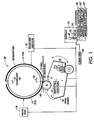
- FIG. 1 one embodiment of a system 100 incorporating features of the disclosed embodiments is illustrated.
- the embodiments disclosed will be described with reference to the embodiments shown in the drawings, it should be understood that the embodiments disclosed can be embodied in many alternate forms of embodiments.
- any suitable size, shape or type of elements or materials could be used.
- system 100 generally comprises an image marking/transfer portion of a printing/copying device, such as that shown in US Patent 4,032,225, issued June 28, 1977 , the disclosure of which is incorporated herein by reference.
- the printing/copying device comprises a xerographic printing/copying system, however, other printing and copying systems may also incorporate the features of the disclosed embodiments.
- image marking/transfer portion with reference to Figure 1 , of a printing/copying device will described herein.
- the marking/image transfer system 100 generally comprises an imaging drum system and a transfer roll system.
- the imaging drum system generally provides for applying images on an imaging drum and the transfer of the image to a suitable media.
- the transfer roll system is generally adapted to cause the engagement and disengagement of a transfer roll with the imaging drum 120 during the image transfer process.
- the imaging drum system comprises a solid ink drum system, although any suitable imaging system that applies images on a drum for transfer to a media can be used.
- the transfer roll system is generally adapted to cause the transfer roll to engage and disengage the imaging drum while maintaining a rotational velocity of the imaging drum at a nominal speed. It is a feature of the disclosed embodiments to provide a motor torque assist for the imaging drum to enable parallel imaging/transferring and reduce motion quality impacts of engagement and disengagement of the transfer roll.
- one embodiment of the imaging drum system includes an imaging drum 120, an imaging drum drive system 150 and a marking device 110.
- Imaging drum 120 is adapted to include at least one pitch 115.
- imaging drum 120 includes a first pitch 115 and a second pitch 117. The boundaries between first and second pitches 115, 117 may be defined by one or more inter-document gaps 123.
- Imaging drum drive system 150 operates to maintain imaging drum 120 at a substantially constant rotational velocity.
- Marking device 110 generally operates to apply an image on at least one pitch 115 of imaging drum 120.
- marking device 110 is capable of applying an image to both pitches, 115, 117.
- One embodiment of the transfer roll system includes a transfer roll 135, a transfer roll drive system 145, and an engagement assembly 140.
- Engagement assembly 140 is adapted to move transfer roll 135 into engagement with imaging drum 120 in the area of a nip 130 to transfer one or more images thereon to media 125.
- Media 125 may include any substrate suitable for applying images thereon and may comprise individual sheets or a continuous roll.
- one example of the motor torque assist includes measuring a drive current of imaging drum drive system 150, recording the drive current of transfer roll drive system 145 during transfer roll 135 and imaging drum 120 engagement and disengagement required to maintain the measured imaging drum drive current, and using the recorded drive current to operate transfer roll drive system 145 to minimize imaging drum velocity variations during subsequent engagement and disengagement.
- Marking device 110, engagement assembly 140, transfer roll drive system 145, and imaging drum drive system 150 may be operated by a controller 155.
- Controller 155 may include logic circuitry for generally controlling the operation of system 100, and include a processor 165 that operates programs in a memory device 170.
- Memory device 170 may also be capable of storing data.
- engagement assembly 140 may include an engagement motor 160 which operates to move transfer roll 135 toward or away from imaging drum 120.
- Other engagement mechanisms and techniques may also be used so long as imaging drum 120 and transfer roll 135 are capable of being brought together and moved apart as described herein.
- System 100 may also include a media transport mechanism (not shown) for transporting media 125 through nip 130.
- Transfer roll drive system 145 is adapted to operate at least in a constant velocity mode and a current drive mode. In the constant velocity drive mode, transfer roll drive system 145 operates to maintain transfer roll 130 substantially at a particular rotational velocity. In the current drive mode, transfer roll drive system 145 operates to drive transfer roll 130 according to a current set point.
- Imaging drum drive system 150 is adapted to operate at least in a constant velocity mode, where imaging drum drive system 150 operates to maintain imaging drum 120 substantially at a particular rotational velocity.
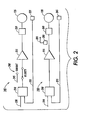
- Figure 2 shows schematic diagrams of exemplary embodiments of transfer roll drive system 145 and imaging drum drive system 150.
- Transfer roll drive system 145 is adapted to operate at least in a constant velocity mode and a current drive mode. In the constant velocity drive mode, transfer roll drive system 145 operates to maintain transfer roll 130 substantially at a particular rotational velocity. In the current drive mode, transfer roll drive system 145 operates to drive transfer roll 130 according to a current set point.
- Transfer roll drive system 145 may include a transfer roll velocity servo controller 210, a transfer roll amplifier 215, a transfer roll motor 220, and a transfer roll velocity sensor 225.
- Controller 155 ( Figure 1 ) may apply a transfer roll velocity set point on signal line 230, and transfer roll velocity sensor 225 may apply a feedback signal on line 235.
- Transfer roll velocity servo controller 210 may then apply a signal to transfer roll amplifier 215 which in turn applies power to transfer roll motor 220.
- transfer roll velocity servo controller 210 When switch 240 is in the velocity position, transfer roll velocity servo controller 210 operates to maintain the velocity of transfer roll 135 substantially at the transfer roll velocity set point.
- transfer roll amplifier 215 When switch 240 is in the current position, transfer roll amplifier 215 operates as a current source, responsive to a current set point applied to signal line 245 by controller 155 ( Figure 1 ).
- Imaging drum drive system 150 is adapted to generally operate at least in a constant velocity mode. In the constant velocity drive mode, imaging drum drive system 150 operates to maintain imaging drum 120 substantially at a particular rotational velocity.
- Imaging drum drive system 150 may include an imaging drum velocity servo controller 250, an imaging drum amplifier 255, an imaging drum motor 260, and an imaging drum velocity sensor 265. Controller 155 ( Figure 1 ) may apply an imaging drum velocity set point on signal line 270, and imaging drum velocity sensor 265 may apply a feedback signal on line 275. Imaging drum velocity servo controller 250 may then apply a signal to imaging drum amplifier 255 which in turn applies power to imaging drum motor 260.
- Imaging drum drive system 150 may also include a current sensor 280 for sensing the current draw of imaging drum motor 260.
- marking device 110 applies a first image to pitch 115.
- engagement assembly 140 causes transfer roll 135 to move toward and engage imaging drum 120, forming nip 130.
- Media 125 is passed through nip 130 and the first image is transferred from imaging drum 120 to media 125 by rotating imaging drum 120 with respect to the surface of media 125.
- marking device 110 may be applying a second image to pitch 117. After the first image is transferred to media 125, if the second image is complete, it may also be transferred to media 125 at nip 130. Otherwise, transfer roll 135 may be disengaged from imaging drum 120 when inter-document gap 123 reaches nip 130.
- transfer roll 135 and imaging drum 120 may then be re-engaged to transfer the second image to media 125.
- Engagement and disengagement of transfer roll 135 and imaging drum 120 is generally performed when inter-document gap is at or near nip 130.
- a load in the range of approximately 500-700 lbs. may be applied to imaging drum 120.
- Full engagement, and thus full loading generally occurs as inter-document gap 123 traverses nip 130, which typically takes place in approximately 50 ms. Without compensating for this load change, the velocity of imaging drum 120 will fluctuate, causing motion quality problems.
- Motion quality requirements may dictate that imaging drum 120 remain within at least +/- 2% of its nominal velocity. Certain techniques used to apply images to imaging drum 120 may allow for some variation in imaging drum velocity, but generally may not be able to compensate for variations significantly larger than this range.
- the disclosed embodiments include driving transfer roll 135 in a manner that compensates for imaging drum velocity disturbances due to engagement and disengagement.
- the disclosed embodiments include a learning, or set-up procedure to record an amount of current applied to transfer roll drive system 145 to maintain a particular current draw of imaging drum drive system 150 during engagement and disengagement as shown in Figure 3 .
- the learning procedure may begin by driving disengaged transfer roll 135 and imaging drum 120 at their respective operational velocities with transfer roll drive system 145 and imaging drum drive system 150 both in a closed loop velocity control mode (step 315).
- a first current draw of imaging drum motor 260 as detected by current sensor 280 (step 320) is recorded by controller 155 in memory 170 (step 325).
- Transfer roll 135 and imaging drum 120 are incrementally moved toward each other, for example, by operating engagement motor 160 (step 330).
- transfer roll drive system 145 is switched to a current drive mode (step 335) where the current set point is initially set such that transfer roll 135 maintains its disengaged velocity (step 340).
- the current set point of transfer roll drive system 145 is adjusted during the engagement process so that the amount of current being drawn by imaging drum drive system 150 is maintained at the first current draw amount (step 345).
- the distance between transfer roll 135 and imaging drum 120 for example, as represented by a position of engagement motor 160, along with the corresponding current set point of transfer roll drive system 145 is recorded in memory 170 for each increment until transfer roll 135 and imaging drum 120 are completely engaged (step 350).
- the distances or positions and current set points may be assembled into a first lookup table 180 that correlates an amount of load compensating drive current with a distance between transfer roll 135 and imaging drum 120 (step 355).
- a similar learning procedure may be implemented for the disengagement of transfer roll 135 and imaging drum 120, that is, the distance between transfer roll 135 and imaging drum 120, along with the corresponding current set point of transfer roll drive system 145 is recorded in memory 170 for each incremental movement until transfer roll 135 and imaging drum 120 are completely disengaged, and the recordations may be assembled into a second lookup table 185.
- Second table 185 should be similar to first table 180 generated for the engagement operation.
- First and second lookup tables 180, 185 may be combined to form a single lookup table 190 that may be used for both engagement and disengagement of transfer roll 135 and imaging drum 120.
- Lookup table 180 may be utilized during later engagement and disengagement operations to minimize disturbances of the imaging drum velocity. For example, a subsequent marking operation may begin with transfer roll 135 and imaging drum 120 disengaged. Controller 155 may cause transfer roll drive system 145 to switch to a closed loop velocity control mode, and may cause disengaged transfer roll 135 and imaging drum 120 to operate at their respective operational velocities. Engagement motor 160 may then be successively incremented, moving transfer roll 135 toward imaging drum 120. As transfer roll 135 and imaging drum 120 begin to engage, transfer roll drive system 145 may be switched to a current drive mode.
- the current set point for transfer roll drive system 145 is set according to look up table 180.
- the current set point for transfer roll drive system 145 for each distance between transfer roll 135 and imaging drum 120 may also be obtained from lookup table 180.
- lookup table 180 may be used for each engagement position and lookup table 185 may be used for each disengagement position.
- lookup table 190 may be used for each engagement position and disengagement position.
- memory device 170 may also include program storage devices 195 for storing software and computer programs incorporating the learning or setup procedure described above to executed by processor 165.
- the software and computer programs may be in the form of machine readable program source code.
- Controller 155 may be generally adapted to utilize program storage devices 195 embodying the machine readable program source code to perform the steps of the disclosed embodiments.
- Program storage devices 195 may include magnetic, optical, semiconductor, or any other type of suitable media.
- transfer roll 135 is driven to compensate for the load on imaging drum 120 to minimize any velocity variations that may occur as a result of the changes in load.
- the system 100 compensates for both transient rotational disturbances and steady state velocity changes due to the load changes associated with engagement and disengagement. Image mis-registration and other related motion quality problems are minimized.
- images may be formed on one or more pitches of imaging drum 120 while other images are being transferred from other pitches to media 125. Thus, image forming and image transferring operations may be performed in parallel, increasing system productivity.
Landscapes
- Physics & Mathematics (AREA)
- General Physics & Mathematics (AREA)
- Electrostatic Charge, Transfer And Separation In Electrography (AREA)
- Ink Jet (AREA)
- Control Or Security For Electrophotography (AREA)
- Tyre Moulding (AREA)
- Labeling Devices (AREA)
Applications Claiming Priority (2)
| Application Number | Priority Date | Filing Date | Title |
|---|---|---|---|
| US10/462,340 US6731891B1 (en) | 2003-06-13 | 2003-06-13 | Transfer roll engagement method for minimizing motion quality disturbances |
| US462340 | 2003-06-13 |
Publications (3)
| Publication Number | Publication Date |
|---|---|
| EP1486833A2 EP1486833A2 (en) | 2004-12-15 |
| EP1486833A3 EP1486833A3 (en) | 2010-03-17 |
| EP1486833B1 true EP1486833B1 (en) | 2013-08-14 |
Family
ID=32176818
Family Applications (1)
| Application Number | Title | Priority Date | Filing Date |
|---|---|---|---|
| EP04013741.6A Expired - Lifetime EP1486833B1 (en) | 2003-06-13 | 2004-06-11 | Transfer roll engagement method for minimizing motion quality disturbances |
Country Status (6)
| Country | Link |
|---|---|
| US (1) | US6731891B1 (pt) |
| EP (1) | EP1486833B1 (pt) |
| JP (1) | JP4688439B2 (pt) |
| CN (1) | CN100444041C (pt) |
| BR (1) | BRPI0401932A (pt) |
| CA (1) | CA2470219C (pt) |
Families Citing this family (12)
| Publication number | Priority date | Publication date | Assignee | Title |
|---|---|---|---|---|
| DE10322502A1 (de) * | 2003-05-19 | 2004-12-23 | OCé PRINTING SYSTEMS GMBH | Umdruckstation für ein elektrografisches Druck- oder Kopiergerät |
| US7065308B2 (en) * | 2003-11-24 | 2006-06-20 | Xerox Corporation | Transfer roll engagement method for minimizing media induced motion quality disturbances |
| US7798631B2 (en) * | 2007-07-23 | 2010-09-21 | Xerox Corporation | System and method for lubricating a transfer roller with an image member |
| US7860417B2 (en) * | 2008-09-12 | 2010-12-28 | Xerox Corporation | System and method for varying transfer pressure applied by a transfer roller in a printer |
| US8126362B2 (en) * | 2008-09-17 | 2012-02-28 | Xerox Corporation | System and method for measuring media thickness with a transfer subsystem in a printer |
| US8317314B2 (en) * | 2010-03-09 | 2012-11-27 | Xerox Corporation | System and method for improving throughput for printing operations in an indirect printing system |
| US8317286B2 (en) * | 2010-03-09 | 2012-11-27 | Xerox Corporation | System and method for improving throughput for duplex printing operations in an indirect printing system |
| US8662657B2 (en) | 2011-04-08 | 2014-03-04 | Xerox Corporation | Print process for duplex printing with alternate imaging order |
| US8882223B2 (en) | 2012-07-31 | 2014-11-11 | Xerox Corporation | Method of printing with a split image revolution |
| US8696104B1 (en) | 2012-10-16 | 2014-04-15 | Xerox Corporation | Motion quality improvement by feed-forward torque control of imaging drum |
| US8827406B1 (en) | 2013-03-15 | 2014-09-09 | Xerox Corporation | Motion quality of a transfix nip by media thickness and/or skew feedforward to nip motor torque |
| US11858260B2 (en) | 2018-04-26 | 2024-01-02 | Hewlett-Packard Development Company, L.P. | Media management using a media management device |
Family Cites Families (9)
| Publication number | Priority date | Publication date | Assignee | Title |
|---|---|---|---|---|
| JPH04242276A (ja) * | 1991-01-17 | 1992-08-28 | Fuji Xerox Co Ltd | 画像形成装置 |
| JPH0844219A (ja) * | 1994-07-29 | 1996-02-16 | Ricoh Co Ltd | 画像形成装置 |
| JP3460425B2 (ja) * | 1995-03-16 | 2003-10-27 | 富士ゼロックス株式会社 | 画像形成装置 |
| JPH0915927A (ja) * | 1995-06-30 | 1997-01-17 | Fuji Xerox Co Ltd | 画像形成装置 |
| JPH117205A (ja) * | 1997-06-17 | 1999-01-12 | Fuji Xerox Co Ltd | 画像形成装置 |
| DE69914399T2 (de) * | 1998-04-20 | 2004-11-11 | Murata Kikai K.K. | Bilderzeugungsgerät |
| JP2000295882A (ja) * | 1999-04-05 | 2000-10-20 | Minolta Co Ltd | 像担持体の駆動制御装置 |
| US6400913B1 (en) | 2000-12-14 | 2002-06-04 | Xerox Corporation | Control registration and motion quality of a tandem xerographic machine using transfuse |
| JP2003316177A (ja) * | 2002-04-22 | 2003-11-06 | Sharp Corp | 転写装置 |
-
2003
- 2003-06-13 US US10/462,340 patent/US6731891B1/en not_active Expired - Lifetime
-
2004
- 2004-06-07 CA CA002470219A patent/CA2470219C/en not_active Expired - Fee Related
- 2004-06-09 BR BR0401932-6A patent/BRPI0401932A/pt not_active IP Right Cessation
- 2004-06-11 EP EP04013741.6A patent/EP1486833B1/en not_active Expired - Lifetime
- 2004-06-11 JP JP2004173582A patent/JP4688439B2/ja not_active Expired - Fee Related
- 2004-06-14 CN CNB2004100485865A patent/CN100444041C/zh not_active Expired - Fee Related
Also Published As
| Publication number | Publication date |
|---|---|
| CN1573603A (zh) | 2005-02-02 |
| JP2005004218A (ja) | 2005-01-06 |
| BRPI0401932A (pt) | 2005-02-22 |
| EP1486833A2 (en) | 2004-12-15 |
| JP4688439B2 (ja) | 2011-05-25 |
| CN100444041C (zh) | 2008-12-17 |
| EP1486833A3 (en) | 2010-03-17 |
| CA2470219C (en) | 2008-09-16 |
| CA2470219A1 (en) | 2004-12-13 |
| US6731891B1 (en) | 2004-05-04 |
Similar Documents
| Publication | Publication Date | Title |
|---|---|---|
| EP1498785B1 (en) | Image forming apparatus with a speed control of a belt | |
| EP1486833B1 (en) | Transfer roll engagement method for minimizing motion quality disturbances | |
| US8000622B2 (en) | Moving body controlling device, intermediate transferring device, and image forming apparatus having the same | |
| JP3497237B2 (ja) | ゼログラフィックプリンタ | |
| US6321044B1 (en) | Image forming apparatus and method | |
| JP3408071B2 (ja) | 画像形成装置 | |
| EP1884835B1 (en) | Image forming apparatus including belt traveling unit which detects drifting of belt position | |
| EP1400870B1 (en) | Image forming apparatus with scale on rotating belt | |
| JPH0844267A (ja) | 複写機 | |
| US4864358A (en) | Color image forming apparatus | |
| JP4774343B2 (ja) | 画像転写装置及び画像形成装置 | |
| US20080285988A1 (en) | Image forming apparatus and recording-medium feeding method | |
| JP2003098792A (ja) | カラー画像形成装置の色ずれ補正装置 | |
| JP2009223229A (ja) | 画像形成装置 | |
| JP2004054144A (ja) | カラー画像形成装置 | |
| JP2007310365A (ja) | 画像形成装置の制御方法 | |
| JPH0895422A (ja) | 画像形成装置 | |
| JP2004198630A (ja) | 複数トナー画像転写方法及び装置・画像形成装置 | |
| JP7823007B2 (ja) | 画像形成装置 | |
| JP4864736B2 (ja) | 画像形成装置 | |
| JP2000338740A (ja) | カラープリンタ | |
| JP2005181507A (ja) | 画像形成装置およびその速度制御方法 | |
| JP2008176149A (ja) | 画像形成装置 | |
| JP2006011317A (ja) | 画像形成装置 | |
| JPH1055096A (ja) | 電子写真現像方式を用いた画像形成装置の現像電圧調整方法 |
Legal Events
| Date | Code | Title | Description |
|---|---|---|---|
| PUAI | Public reference made under article 153(3) epc to a published international application that has entered the european phase |
Free format text: ORIGINAL CODE: 0009012 |
|
| AK | Designated contracting states |
Kind code of ref document: A2 Designated state(s): AT BE BG CH CY CZ DE DK EE ES FI FR GB GR HU IE IT LI LU MC NL PL PT RO SE SI SK TR |
|
| AX | Request for extension of the european patent |
Extension state: AL HR LT LV MK |
|
| PUAL | Search report despatched |
Free format text: ORIGINAL CODE: 0009013 |
|
| AK | Designated contracting states |
Kind code of ref document: A3 Designated state(s): AT BE BG CH CY CZ DE DK EE ES FI FR GB GR HU IE IT LI LU MC NL PL PT RO SE SI SK TR |
|
| AX | Request for extension of the european patent |
Extension state: AL HR LT LV MK |
|
| 17P | Request for examination filed |
Effective date: 20100917 |
|
| AKX | Designation fees paid |
Designated state(s): DE FR GB |
|
| 17Q | First examination report despatched |
Effective date: 20111020 |
|
| GRAP | Despatch of communication of intention to grant a patent |
Free format text: ORIGINAL CODE: EPIDOSNIGR1 |
|
| INTG | Intention to grant announced |
Effective date: 20130325 |
|
| GRAS | Grant fee paid |
Free format text: ORIGINAL CODE: EPIDOSNIGR3 |
|
| GRAA | (expected) grant |
Free format text: ORIGINAL CODE: 0009210 |
|
| AK | Designated contracting states |
Kind code of ref document: B1 Designated state(s): DE FR GB |
|
| REG | Reference to a national code |
Ref country code: GB Ref legal event code: FG4D |
|
| REG | Reference to a national code |
Ref country code: DE Ref legal event code: R096 Ref document number: 602004043011 Country of ref document: DE Effective date: 20131010 |
|
| PLBE | No opposition filed within time limit |
Free format text: ORIGINAL CODE: 0009261 |
|
| STAA | Information on the status of an ep patent application or granted ep patent |
Free format text: STATUS: NO OPPOSITION FILED WITHIN TIME LIMIT |
|
| 26N | No opposition filed |
Effective date: 20140515 |
|
| REG | Reference to a national code |
Ref country code: DE Ref legal event code: R097 Ref document number: 602004043011 Country of ref document: DE Effective date: 20140515 |
|
| REG | Reference to a national code |
Ref country code: FR Ref legal event code: PLFP Year of fee payment: 13 |
|
| PGFP | Annual fee paid to national office [announced via postgrant information from national office to epo] |
Ref country code: DE Payment date: 20160524 Year of fee payment: 13 Ref country code: GB Payment date: 20160527 Year of fee payment: 13 |
|
| PGFP | Annual fee paid to national office [announced via postgrant information from national office to epo] |
Ref country code: FR Payment date: 20160526 Year of fee payment: 13 |
|
| REG | Reference to a national code |
Ref country code: DE Ref legal event code: R119 Ref document number: 602004043011 Country of ref document: DE |
|
| GBPC | Gb: european patent ceased through non-payment of renewal fee |
Effective date: 20170611 |
|
| REG | Reference to a national code |
Ref country code: FR Ref legal event code: ST Effective date: 20180228 |
|
| PG25 | Lapsed in a contracting state [announced via postgrant information from national office to epo] |
Ref country code: GB Free format text: LAPSE BECAUSE OF NON-PAYMENT OF DUE FEES Effective date: 20170611 Ref country code: DE Free format text: LAPSE BECAUSE OF NON-PAYMENT OF DUE FEES Effective date: 20180103 |
|
| PG25 | Lapsed in a contracting state [announced via postgrant information from national office to epo] |
Ref country code: FR Free format text: LAPSE BECAUSE OF NON-PAYMENT OF DUE FEES Effective date: 20170630 |