EP1488068B1 - Verschlussvorrichtung mit flexiblen seitlichen rändern - Google Patents
Verschlussvorrichtung mit flexiblen seitlichen rändern Download PDFInfo
- Publication number
- EP1488068B1 EP1488068B1 EP03707933A EP03707933A EP1488068B1 EP 1488068 B1 EP1488068 B1 EP 1488068B1 EP 03707933 A EP03707933 A EP 03707933A EP 03707933 A EP03707933 A EP 03707933A EP 1488068 B1 EP1488068 B1 EP 1488068B1
- Authority
- EP
- European Patent Office
- Prior art keywords
- edges
- shutter
- reintroduction
- guideways
- reintroduction element
- Prior art date
- Legal status (The legal status is an assumption and is not a legal conclusion. Google has not performed a legal analysis and makes no representation as to the accuracy of the status listed.)
- Expired - Lifetime
Links
- 239000013536 elastomeric material Substances 0.000 claims abstract description 5
- 238000006073 displacement reaction Methods 0.000 claims description 4
- 229920002635 polyurethane Polymers 0.000 claims description 4
- 239000004814 polyurethane Substances 0.000 claims description 4
- 239000012781 shape memory material Substances 0.000 claims description 4
- 230000000694 effects Effects 0.000 claims description 3
- 239000000835 fiber Substances 0.000 claims description 3
- 239000004760 aramid Substances 0.000 claims description 2
- 239000003365 glass fiber Substances 0.000 claims description 2
- 230000002787 reinforcement Effects 0.000 claims description 2
- 229920003235 aromatic polyamide Polymers 0.000 claims 1
- 101001017827 Mus musculus Leucine-rich repeat flightless-interacting protein 1 Proteins 0.000 description 21
- 235000019589 hardness Nutrition 0.000 description 13
- 239000011324 bead Substances 0.000 description 3
- 239000000463 material Substances 0.000 description 3
- 230000006378 damage Effects 0.000 description 2
- 239000002184 metal Substances 0.000 description 2
- 230000008439 repair process Effects 0.000 description 2
- 238000013459 approach Methods 0.000 description 1
- 229920006231 aramid fiber Polymers 0.000 description 1
- 230000000903 blocking effect Effects 0.000 description 1
- 230000006835 compression Effects 0.000 description 1
- 238000007906 compression Methods 0.000 description 1
- 239000013013 elastic material Substances 0.000 description 1
- 229920001971 elastomer Polymers 0.000 description 1
- 239000000806 elastomer Substances 0.000 description 1
- 239000004033 plastic Substances 0.000 description 1
- 229920003023 plastic Polymers 0.000 description 1
Images

Classifications
-
- E—FIXED CONSTRUCTIONS
- E06—DOORS, WINDOWS, SHUTTERS, OR ROLLER BLINDS IN GENERAL; LADDERS
- E06B—FIXED OR MOVABLE CLOSURES FOR OPENINGS IN BUILDINGS, VEHICLES, FENCES OR LIKE ENCLOSURES IN GENERAL, e.g. DOORS, WINDOWS, BLINDS, GATES
- E06B9/00—Screening or protective devices for wall or similar openings, with or without operating or securing mechanisms; Closures of similar construction
- E06B9/56—Operating, guiding or securing devices or arrangements for roll-type closures; Spring drums; Tape drums; Counterweighting arrangements therefor
- E06B9/58—Guiding devices
- E06B9/581—Means to prevent or induce disengagement of shutter from side rails
-
- E—FIXED CONSTRUCTIONS
- E06—DOORS, WINDOWS, SHUTTERS, OR ROLLER BLINDS IN GENERAL; LADDERS
- E06B—FIXED OR MOVABLE CLOSURES FOR OPENINGS IN BUILDINGS, VEHICLES, FENCES OR LIKE ENCLOSURES IN GENERAL, e.g. DOORS, WINDOWS, BLINDS, GATES
- E06B9/00—Screening or protective devices for wall or similar openings, with or without operating or securing mechanisms; Closures of similar construction
- E06B9/56—Operating, guiding or securing devices or arrangements for roll-type closures; Spring drums; Tape drums; Counterweighting arrangements therefor
- E06B9/58—Guiding devices
-
- E—FIXED CONSTRUCTIONS
- E06—DOORS, WINDOWS, SHUTTERS, OR ROLLER BLINDS IN GENERAL; LADDERS
- E06B—FIXED OR MOVABLE CLOSURES FOR OPENINGS IN BUILDINGS, VEHICLES, FENCES OR LIKE ENCLOSURES IN GENERAL, e.g. DOORS, WINDOWS, BLINDS, GATES
- E06B9/00—Screening or protective devices for wall or similar openings, with or without operating or securing mechanisms; Closures of similar construction
- E06B9/56—Operating, guiding or securing devices or arrangements for roll-type closures; Spring drums; Tape drums; Counterweighting arrangements therefor
- E06B9/58—Guiding devices
- E06B2009/585—Emergency release to prevent damage of shutter or guiding device
Definitions
- the invention relates to a shutter device for closing a bay or other opening, the flap having flexible edges projecting from the plane of the flap and cooperating with guideways, at least one reintroduction element being provided to reintroduce said edges into the guide paths when these edges are disengaged from the latter under the action of a force exerted on these edges in a direction transverse to the guideways, a contact surface being formed during this reintroduction between the reintroduction element and the corresponding edge.
- the invention relates, in particular, to a flap device whose side edges of the flap can be disengaged from the guideways, for example, when an obstacle is between the guideways when the flap is closed or when vehicle collides with the flap.
- the reintroduction element provided at the location of the upper part of the guideways makes it possible to reintroduce the lateral edges of the flap in the guideways during its upward movement.
- One of the essential aims of the present invention is to provide a shutter device whose side edges and the reintroduction element can not be damaged when a force greater than a predetermined force is exerted on these flap edges during the upward movement. of the last.
- the reintroduction element and the projecting edge cooperate with each other in such a way that, as soon as the force exerted on the edge in a direction transverse to the paths of guidance, exceeds a certain value, the contact area between the reintroduction element and the edge corresponding is displaced relative to a longitudinal axis of the projecting edge, located at a distance from the contact surface, allowing the clearance of the edge relative to the reintroduction element.
- said flap edges are made of a flexible and deformable shape memory material so that these edges return to their original shape after a deformation under the effect of the aforesaid displacement of the contact surface.
- edges are made of an elastomeric material. These edges have, in particular, a Shore A hardness between 65 ° and 100 ° and are preferably made at least partially of polyurethane.
- the hardness of the edges is chosen in such a way that, when a traction force transverse to the longitudinal direction of the guideways is exerted on said edges, these edges emerge from their corresponding guiding path without being significantly deformed, whereas, when this force exceeds a certain value, these edges are deformed more temporarily in order to be able to disengage from the reintroduction element.
- the reintroduction member is resiliently mounted on a support so that, when said pulling force exceeds the aforesaid determined value, the reintroduction member is temporarily moved. under the action of the corresponding edge to allow the latter to emerge relative to the reintroduction element.
- the reintroduction element consists of a deformable shape memory material so that, when said traction force exceeds the aforementioned determined value, the reintroduction element is deformed. under the action of the corresponding edge when the latter is released relative to the reintroduction element.
- the present invention relates to a flap device cooperating with drive means, such as a drum whose axis is connected to the shaft of an electric motor.
- the flap moves in downward and upward movement between, respectively, a closed position and an open position, and is intended for closing a bay in a wall or passage, such as a corridor.
- any planar element at least partially flexible or flexible such as a tarpaulin, a plastic strip, a wire mesh, a trellis , a metal sheet, a sectional door, etc.
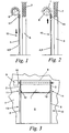
- the shutter device is shown schematically in the closed position, while in the Figures 2 and 3 the shutter device is shown in the open position.
- This device comprises a flap 1 with side edges 2 and 3 protruding from the plane of the flap which are advantageously formed by a continuous bead or by a succession of small blocks articulated with respect to each other moving in paths 4 and 5.
- Guideways 4 and 5 are provided on either side of a bay 6 which is present in a wall 7.
- a drum 8 on which the flap 1 can be wound.
- Drive means 9 such as for example an electric motor, drive a shaft 10 which extends along the axis of the drum 8 in order to be able to wind the shutter 1 on the drum 8 to bring it into the open position or to be able to unroll it towards its closed position.
- the guideways 4 and 5 comprise at their upper part 11 a reintroduction element 12.
- This reintroduction element 12 makes it possible to reintroduce the lateral edges 2 and 3 into the guide tracks 4 and 5 during the opening of the shutter 1 when they have disengaged from the lower part 13 of the guide tracks 4 and 5. Below the reintroduction element 12.
- the lateral edges 2 and 3 can be released, for example, when an obstacle is between the guideways 4 and 5 when closing the shutter 1 or when, for example, a vehicle collides with shutter 1.
- the guideways 4 and 5 have a U-shaped section with two wings 19 and 20.
- the edges of these wings 19 and 20 are folded towards one another by delimiting a slot 21.
- a channel 22 formed in by which the side edges 2 and 3 of the shutter 1 are guided while the area of the shutter 1 near these edges 2 and 3 extends to 21.
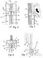
- the Figures 4 to 7 represent the reintroduction element 12 on a larger scale.
- This reintroduction element 12 comprises a base block 16 housed between the upper part 11 of the guide tracks 4 and 5 and the lower part 13 thereof.
- Two parallel cylinders 17 and 18 extend on this base block 16 at a distance from each other, so that said channel 22 extends between these cylinders 17 and 18 and that, therefore, the Side edges 2 and 3 of the shutter 1 can move through the space formed between these cylinders 17 and 18.
- a guide member 14 and 15 is provided on each cylinder 17 and 18 protruding from the guideways 4 and 5.
- These guide members 14 and 15 have a rounded surface at their side facing the portion lower 13 guideways 4 and 5.
- the distance between the guide members 14 and 15 substantially corresponds to the thickness of the side edges 2 and 3 of the flap 1.
- the guide members 14 and 15 extend over a distance on the upper portion 11 of the guideways 4 and 5 and are, at their facing surface, each provided with a round 23 and 24 located opposite this upper portion 11 of the guideways 4 and 5.
- the distance between these rounds 23 and 24 is slightly greater than the thickness of the flap 1, but less than the thickness of the side edges 2 and 3, of so that during the upward or downward movement of the flap 1, while the side edges 2 and 3 are guided in the guideways 4 and 5, the flap can move between these rounds 23 and 24.
- edges 2 and 3 of the shutter 1 When the side edges 2 and 3 of the shutter 1 have disengaged from the lower part 13 of the guideways 4 and 5, these edges 2 and 3 are reintroduced into the guideways 4 and 5 during the upward movement of the shutter 1.
- the lateral edges 2 and 3 are, at the location of the guide members 14 and 15, guided by said rounded surface of the latter towards a position opposite the slot 21 and the channel 22.
- the rounds 23 and 24 rest against the lateral edges 2 and 3 of the shutter 1 on either side of the latter's plane. causing these edges 2 and 3 to enter the upper portion 11 of the guide tracks 4 and 5.
- the side edges 2 and 3 of the flap 1, cooperating with the reintroduction element described above consist of a succession of rigid teeth articulated with respect to each other. .
- a relatively large force is exerted on the edges of the shutter, for example, because of the wind or because a vehicle has not yet passed completely through the bay 6.
- each tooth successively bears against the guide member 14 and 15 before being reintroduced into the guide path. Therefore, the entire reintroduction force is permanently applied to a single tooth that is in contact with a single point on the guide member 14 or 15. When this force is greater than the resistance of this tooth, it breaks and renders the shutter device non-functional.
- the lateral edges 2 and 3 of the shutter 1 are made of a material that can be temporarily deformed, thus presenting a shape memory.
- the hardness of the side edges 2 and 3 of the shutter 1, the thickness of the projecting edge 2 and 3 and the distance between the guide members 14 and 15 are chosen so that, when said force exerted on the lateral edges 2 and 3 by the reintroduction element exceeds a predetermined value, these edges 2 and 3 are deformed in an elastic manner by allowing the edges 2 and 3 to disengage from the reintroduction element 12.
- Said determined value of the force exerted on the lateral edges 2 and 3 is less than the breaking force of these lateral edges 2 and 3, so that these edges can not be broken, but deform when a higher force is exerted on these edges.
- the side edges 2 and 3 of the shutter 1 consist of an elastomeric material, such as polyurethane. It has been found that such an elastomer with a Shore A hardness between 75 and 100 and, in particular, a Shore A hardness between 75 and 95 gives excellent results. Preferably, the side edges 2 and 3 of the shutter 1 have a Shore A hardness between 90 and 95.
- the lateral edges deform, as shown in Figures 8 to 9 by causing the lateral edges 2 and 3 of the reintroduction element 13 to disengage.
- the lateral edges 2 and 3 of the shutter 1, represented in the FIGS. Figures 4 to 7 are constituted by a bead, so that, during this deformation, it is compressed gradually so as to be able to pass through the space between said rounds 23 and 24.
- the contact surface 37, between the element reintroduction 13 and the lateral edges 2 and 3, then undergoes a displacement relative to the axis of these lateral edges 2 and 3. This contact surface 37 approaches the central axis of the side edges 2 and 3 during the compression of these.
- FIG. 8 to 11 represent successive stages of this deformation of a lateral edge 2 or 3 of the shutter 1 when a traction force in the direction of the arrow 25 is exerted on this edge by the shutter 1. After the lateral edges 2 and 3 are are released from the reintroduction element 12, they return to their original shape and dimensions, as shown in FIG. figure 11 .
- the side edges 2 and 3 of the shutter 1 have a hardness of a value lower than the values mentioned above, they may deform too strongly, and, therefore, to emerge from the lower part 13 of the guideways 4 and 5 because of the action of the wind on the flap 1 when it is in its closed position.
- edges 2 and 3 are, in particular, chosen in such a way that, when a traction force transverse to the longitudinal direction of the guideways 4 and 5 is exerted on said edges 2 and 3, these edges are they free from their corresponding guide paths 4 and 5 without being considerably deformed, whereas when this force exceeds said determined value, these edges 2 and 3 are deformed more temporarily in order to be able to disengage from the reintroduction element 12 .
- the aforementioned values for the hardness of the edges 2 and 3 is, more specifically, applicable when the ratio between the distance separating the guide members 14 and 15, in particular the distance between the rounds 23 and 24, and the thickness of the lateral edges. 2 and 3 is between 3/10 and 7/10, in particular between 3.5 / 10 and 6.5 / 10. This ratio is preferably between 4.5 / 10 and 5.5 / 10.
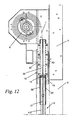
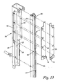
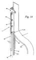
- the Figures 12 to 14 represent a second embodiment of the reintroduction element according to the invention.
- the upper portion 11 of the guideways 4 and 5 comprises a frame 26 having a U-shaped section with a base 27 and two wings 28 and 29.
- the wings 28 and 29 are folded outwardly so that to form two flanges 30 and 31 which extend substantially parallel to the base 27.
- a plate 32 and 33 is fixed on each of these flanges 30 and 31 by means of bolts 34.
- the plates 32 and 33 are each provided with a substantially continuous edge directed towards each other so that a slot 35 is formed between these plates 32 and 33.
- the protruding side edge 2 or 3 of the flap 1 is housed in the space formed between the flanges 28 and 29 of the frame 26, the flap 1 then extending through the slot 35.
- the width of this slot 35 is slightly greater than the thickness of the flap 1 and less than the thickness of the projecting edge 2 and 3, so that this edge can not leave the space between the flanges 28 and 29 without being considerably deformed, while allowing the flap itself to slide between the edges next to dishes 32 and 33.
- the guideways 4 and 5 are fixed on the frame 26 between the wings 28 and 29 in such a way that the slot 35 between the plates 32 and 33 is aligned with the slot 21 between the wings 19 and 20 of the paths 4 and 5.
- the lower part 13 of the guideways 4 and 5 is separated from the upper part 11 by a recess 36 provided in the guideways 4 and 5.
- Each of the plates 32 and 33 has at its lower end a guide member 14 and 15 which is arranged opposite the recess 36.
- These guide members 14 and 15 are in the form of a circle whose axis extends transversely to the longitudinal direction of the guideways 4 and 5 and to the plane of the flap 1.
- the reintroduction element 12 thus comprises said plates 32 and 33 with the guide members 14 and 15.
- the side edges 2 and 3 consist of a continuous bead with a circular section with a diameter of 6 mm and when the distance between the guide members 14 and 15 is of the order of 3 mm.
- the thickness of the flap 1 in the area near the side edges 2 and 3 is, for example, 2 mm.
- the guide members 14 and 15 rest on the side edges 2 and 3 of the shutter 1 on a surface of contact 37 on either side of the plane of the flap 1 to reintroduce these edges 2 and 3 in the upper part 11 of the guideways 4 and 5.
- the lower end of the side edges 2 and 3 of the flap 1 are inserted manually, for example, into the upper part 11 of the guide tracks 4. and 5. Then, the shutter device can operate again without additional repairs being necessary.
- the guide members 14 and 15 are made of a rigid material, such as for example metal, and that the lateral edges are made of an elastically deformable material, it is perfectly possible that the lateral edges 2 and 3 of the flap 1 comprise a succession of rigid teeth, while the guide members 14 and 15 are made of an elastic material. In this way, during the reintroduction of the side edges 2 and 3 of the shutter 1 in the guideways 4 and 5, a contact surface 37 is formed successively between each tooth and the guide members 14 and 15. When a force traction force greater than a determined value is exerted on the side edges 2 and 3 of the flap 1, the guide members 14 and 15 are further deformed in order to disengage these lateral edges 2 and 3 from the reintroduction element 12.
- the reintroduction element 12 is resiliently mounted on a support so that, when said pulling force exceeds the aforesaid determined value, the reintroducing element 12 is temporarily moved under the action of the side edges 2 and 3 to allow them to emerge relative to this reintroduction element 12.
- the contact surface between them gradually moves on the lateral edges 2 and 3 away from the shutter 1.
- the side edges 2 and 3 of the shutter 1 consist of elastic discrete elements extending one after the other in the longitudinal direction of the lateral edges. of the shutter.
- Such elements may, for example, form a succession of teeth.
- These teeth are, in particular, made of an elastomeric material, such as polyurethane, and have the same hardness as the side edges 2 and 3 of the shutter 1 of the first and second embodiments of the invention described above. .
- the width of the slot 21 of the lower portion 13 of the guideways 4 and 5 can be adjusted to allow the side edges 2 and 3 of the shutter 1 to be disengaged relative to each other. at this lower part 13 by deforming somewhat under the action of a transverse traction force to the guideways 4 and 5. In such a case, it is not necessary that the wings 19 and 20 of the guideways 4 and 5 move away from each other as described above.
- edges 2 and 3 When the lateral edges 2 and 3 are then released from the guideways 4 and 5, and a high traction force is exerted on these edges 2 and 3 during the upward movement of the shutter 1, these edges 2 and 3 deform more in order to be able to disengage from the reintroduction element 12.
- the side edges 2 and 3 of the shutter 1 are provided with a rack which cooperates with a toothed wheel actuated by said drive means, it is advantageous to provide an armature in these side edges 2 and 3. It is provided, in particular, a reinforcement of fibers, in particular of glass fibers or of aramid fibers. These fibers extend along the length of the lateral edges 2 and 3, in these edges 2 and 3 themselves or in the region of the shutter 1 near the edges 2 and 3.
Landscapes
- Engineering & Computer Science (AREA)
- Structural Engineering (AREA)
- Architecture (AREA)
- Civil Engineering (AREA)
- Operating, Guiding And Securing Of Roll- Type Closing Members (AREA)
- Blinds (AREA)
- Window Of Vehicle (AREA)
- Curtains And Furnishings For Windows Or Doors (AREA)
- Road Signs Or Road Markings (AREA)
- Specific Sealing Or Ventilating Devices For Doors And Windows (AREA)
- Support Devices For Sliding Doors (AREA)
Claims (14)
- Vorrichtung mit Laden zum Verschließen eines Wandausschnitts (6) oder einer anderen Öffnung, umfassend biegsame Ränder (2, 3), die in Bezug auf die Ebene des Ladens (1) vorspringen und mit Führungsbahnen (4, 5) zusammenarbeiten, wobei mindestens ein Wiedereinführungselement (12) vorgesehen ist, das es ermöglicht, die Ränder (2, 3) wieder in die Führungsbahnen (4, 5) einzuführen, wenn sich diese Ränder (2, 3) unter der Einwirkung einer Kraft von ihnen gelöst haben, die auf diese Ränder (2, 3) in einer Richtung quer zu den Führungswegen (4, 5) ausgeübt wurde, wobei während dieser Wiedereinführung eine Kontaktfläche (37) zwischen dem Wiedereinführungselement (12) und dem entsprechenden Rand (2, 3) gebildet wird, dadurch gekennzeichnet, dass die Seitenränder (2, 3) mindestens teilweise aus einem Elastomermaterial gebildet sind, so dass die Kontaktfläche (37) größer wird, wenn die Kraft zunimmt, indem diese Kraft auf der Kontaktfläche (37) verteilt wird.
- Vorrichtung mit Laden nach Anspruch 1, dadurch gekennzeichnet, dass das Wiedereinführungselement (12) und der vorspringende Rand (2, 3) derart miteinander zusammenarbeiten, dass, sobald die auf den Rand (2, 3) ausgeübte Kraft einen bestimmten Wert übersteigt, die Kontaktfläche (37) eine Verschiebung in Bezug auf eine Längsachse des vorspringenden Rands (2, 3) erfährt, die in einer bestimmten Entfernung von der Kontaktfläche (2, 3) angeordnet ist, was die Lösung des Rands (2, 3) in Bezug auf das Wiedereinführungselement (12) ermöglicht.
- Vorrichtung nach Anspruch 1 oder 2, dadurch gekennzeichnet, dass die Ränder (2, 3) aus einem biegsamen und verformbaren Material mit Formgedächtnis gebildet sind, so dass diese Ränder (2, 3) nach einer Verformung unter der Einwirkung der Verschiebung der Kontaktfläche (37) wieder ihre ursprüngliche Form annehmen.
- Vorrichtung mit Laden nach einem der Ansprüche 1 bis 3, dadurch gekennzeichnet, dass die Ränder (2, 3) eine Shorehärte A zwischen 75° und 100° aufweisen.
- Vorrichtung nach einem der Ansprüche 1 bis 4, dadurch gekennzeichnet, dass die Ränder (2, 3) mindestens teilweise aus Polyurethan gebildet sind.
- Vorrichtung nach einem der Ansprüche 1 bis 5, dadurch gekennzeichnet, dass die Seitenränder (2, 3) des Ladens (1) mit einer Armierung aus Fasern, insbesondere Glasfasern oder Aramidfasern, versehen sind.
- Vorrichtung nach Anspruch 6, dadurch gekennzeichnet, dass sich die oben genannten Fasern entlang der Länge der Ränder (2, 3) erstrecken.
- Vorrichtung nach einem der Ansprüche 1 bis 7, dadurch gekennzeichnet, dass die Härte der Ränder (2, 3) derart gewählt wird, dass sich, wenn eine Zugkraft quer zur Längsrichtung der Führungsbahnen (4, 5) auf die Ränder (2, 3) ausgeübt wird, diese Ränder (2, 3) von ihrer entsprechenden Führungsbahn (4, 5) lösen, ohne wesentlich verformt zu werden, während sich, wenn diese Kraft einen bestimmten Wert übersteigt, diese Ränder (2, 3) vorübergehend stärker verformen, um sich vom Wiedereinführungselement lösen zu können.
- Vorrichtung nach einem der Ansprüche 1 bis 8, dadurch gekennzeichnet, dass das Wiedereinführungselement (12) auf elastische Weise an einem Träger montiert ist, so dass, wenn die Zugkraft den oben genannten bestimmten Wert übersteigt, das Wiedereinführungselement (12) vorübergehend unter der Einwirkung des entsprechenden Rands (2, 3) verschoben wird, um zu ermöglichen, dass sich der Letztgenannte in Bezug auf das Wiedereinführungselement (12) löst.
- Vorrichtung nach einem der Ansprüche 1 bis 9, dadurch gekennzeichnet, dass das Wiedereinführungselement (12) aus einem verformbaren Material mit Formgedächtnis gebildet ist, so dass, wenn die Zugkraft den oben genannten bestimmten Wert übersteigt, das Wiedereinführungselement (12) unter der Einwirkung des entsprechenden Rands (2, 3) verformt wird, wenn sich der Letztgenannte in Bezug auf das Wiedereinführungselement (12) löst.
- Vorrichtung nach einem der Ansprüche 1 bis 10, dadurch gekennzeichnet, dass sie mit mindestens zwei Wiedereinführungselementen (12) versehen ist, die zu beiden Seiten des Ladens angeordnet sind.
- Vorrichtung nach einem der Ansprüche 1 bis 11, dadurch gekennzeichnet, dass die Ränder (2, 3) im Wesentlichen durchgehend sind.
- Vorrichtung nach einem der Ansprüche 1 bis 11, dadurch gekennzeichnet, dass die Ränder (2, 3) aus separaten Elementen gebildet sind, die sich nacheinander in Längsrichtung der Seitenränder (2, 3) des Ladens (1) erstrecken.
- Vorrichtung nach einem der Ansprüche 1 bis 13, dadurch gekennzeichnet, dass die Ränder (2, 3) Teil des Ladens (1) sind.
Applications Claiming Priority (3)
| Application Number | Priority Date | Filing Date | Title |
|---|---|---|---|
| BE200200197 | 2002-03-20 | ||
| BE2002/0197A BE1014712A3 (fr) | 2002-03-20 | 2002-03-20 | Dispositif a volet presentant des bords lateraux flexibles |
| PCT/BE2003/000043 WO2003078783A1 (fr) | 2002-03-20 | 2003-03-17 | Dispositif a volet presentant des bords lateraux flexibles |
Publications (2)
| Publication Number | Publication Date |
|---|---|
| EP1488068A1 EP1488068A1 (de) | 2004-12-22 |
| EP1488068B1 true EP1488068B1 (de) | 2011-03-02 |
Family
ID=27810209
Family Applications (1)
| Application Number | Title | Priority Date | Filing Date |
|---|---|---|---|
| EP03707933A Expired - Lifetime EP1488068B1 (de) | 2002-03-20 | 2003-03-17 | Verschlussvorrichtung mit flexiblen seitlichen rändern |
Country Status (27)
| Country | Link |
|---|---|
| US (1) | US7416014B2 (de) |
| EP (1) | EP1488068B1 (de) |
| JP (1) | JP4521191B2 (de) |
| KR (1) | KR100997865B1 (de) |
| CN (1) | CN100482916C (de) |
| AR (1) | AR039612A1 (de) |
| AT (1) | ATE500397T1 (de) |
| AU (1) | AU2003212122B2 (de) |
| BE (1) | BE1014712A3 (de) |
| BR (1) | BR0308581B1 (de) |
| CA (1) | CA2479548C (de) |
| DE (1) | DE60336211D1 (de) |
| DK (1) | DK1488068T3 (de) |
| ES (1) | ES2360285T3 (de) |
| GE (1) | GEP20074229B (de) |
| IL (2) | IL164134A0 (de) |
| MX (1) | MXPA04009129A (de) |
| MY (1) | MY151843A (de) |
| NO (1) | NO336649B1 (de) |
| NZ (1) | NZ535560A (de) |
| PL (1) | PL210111B1 (de) |
| PT (1) | PT1488068E (de) |
| RU (1) | RU2310054C2 (de) |
| TW (1) | TWI269829B (de) |
| UA (1) | UA79275C2 (de) |
| WO (1) | WO2003078783A1 (de) |
| ZA (1) | ZA200408444B (de) |
Families Citing this family (30)
| Publication number | Priority date | Publication date | Assignee | Title |
|---|---|---|---|---|
| US20080093037A1 (en) * | 2004-12-10 | 2008-04-24 | Bernard Kraeutler | Door Provided With a Curtain Which is Raisable by Winding and Has an Improved Lateral Tightness |
| EP1840321A1 (de) * | 2006-03-29 | 2007-10-03 | Dynaco International S.A. | Vorrichtung zum Führen eines Rollvorhangs |
| US7748431B2 (en) * | 2006-06-05 | 2010-07-06 | Rite-Hite Holding Corporation | Track and guide system for a door |
| US20070277943A1 (en) * | 2006-06-05 | 2007-12-06 | Rite-Hite Holding Corporation | Track and guide system for a door |
| US8037921B2 (en) * | 2006-06-05 | 2011-10-18 | Rite-Hite Holding Corporation | Track and guide system for a door |
| EP1956176A1 (de) * | 2007-02-07 | 2008-08-13 | Dynaco International S.A. | Vorrichtung mit aufwickelbarem Vorhang |
| EP2003284A1 (de) * | 2007-06-13 | 2008-12-17 | Dynaco International S.A. | Verschlussvorrichtung und Element zur Wiedereinführung einer Verschlussvorrichtung in eine Führungsschiene |
| FR2918698B1 (fr) * | 2007-07-12 | 2009-10-02 | Maviflex Sa | Montant modulaire pour porte de manutention a rideau souple |
| US8408274B2 (en) | 2009-10-26 | 2013-04-02 | Rajiva Dwarka | Architectural apparatus and method |
| TWI499713B (zh) * | 2009-11-06 | 2015-09-11 | Komatsu Denki Sangyo Kabushiki Kaisha | 薄片活動遮門的薄片導引 |
| CN102561921B (zh) * | 2010-12-29 | 2015-06-24 | 皇田工业股份有限公司 | 防脱纱式遮阳帘的制造方法 |
| TW201241297A (en) * | 2011-04-06 | 2012-10-16 | Komatsu Denki Sangyo Kabushiki Kaisha | Sheet shutter |
| US20170009524A1 (en) * | 2011-05-11 | 2017-01-12 | Rajiva A. Dwarka | Retractable curtain panel and enhanced stiffeners |
| US20130068400A1 (en) * | 2011-05-11 | 2013-03-21 | Rajiva A. Dwarka | Retractable curtain panel with track guide |
| US20160319593A1 (en) * | 2011-05-11 | 2016-11-03 | Rajiva A. Dwarka | Retractable curtain panel with track guide |
| US9347258B2 (en) | 2011-05-11 | 2016-05-24 | Rajiva A. Dwarka | Retractable curtain panel with track guide |
| US9127501B1 (en) * | 2012-01-10 | 2015-09-08 | Stoebich Brandschutz Gmbh | Lead system for a fire and smoke protection device |
| US9249621B2 (en) | 2012-01-18 | 2016-02-02 | Rajiva A. Dwarka | Coil brush curtain assembly |
| US9493984B2 (en) | 2013-04-12 | 2016-11-15 | Rite-Hite Holding Corporation | Systems and methods to retain and refeed door curtains |
| US9222304B2 (en) | 2013-04-12 | 2015-12-29 | Rite-Hite Holding Corporation | Systems and methods to retain and refeed door curtains |
| US9323130B2 (en) * | 2013-06-11 | 2016-04-26 | Raytheon Company | Thermal control in variable aperture mechanism for cryogenic environment |
| TW201515613A (zh) * | 2013-10-30 | 2015-05-01 | Macauto Ind Co Ltd | 模造導軌裝置 |
| JP6453442B2 (ja) * | 2014-08-13 | 2019-01-16 | ライト−ハイト ホールディング コーポレイション | ドアカーテンを保持および再供給するシステムおよび方法 |
| US10174545B2 (en) * | 2016-02-12 | 2019-01-08 | Cornellcookson, Llc | Fabric fire rated door |
| US10309153B2 (en) * | 2016-09-26 | 2019-06-04 | Draper, Inc. | Support system for rolled material |
| US11142946B2 (en) * | 2017-12-07 | 2021-10-12 | Innomotive Solutions Group Inc. | Roller-shutter door system |
| US11643864B2 (en) * | 2018-01-23 | 2023-05-09 | Pella Corporation | Screen edge retention and screen rethreading features for a hidden screen assembly and a fenestration assembly |
| EP4582664A3 (de) | 2018-11-30 | 2025-12-17 | Rytec Corporation | Türanordnung mit türplatte mit weichem boden |
| RU195067U1 (ru) * | 2019-07-01 | 2020-01-14 | Грухин Сергей Васильевич | Съёмная шторка формующей машины для формования железобетонных изделий, армированных одинарной арматурной сеткой |
| US20240384593A1 (en) * | 2023-05-18 | 2024-11-21 | Asi Doors, Inc. | Refeed structure and roll-up door assembly |
Family Cites Families (12)
| Publication number | Priority date | Publication date | Assignee | Title |
|---|---|---|---|---|
| US1786054A (en) * | 1927-02-19 | 1930-12-23 | Rolscreen Co | Roller-screen structure |
| US1694314A (en) * | 1927-02-19 | 1928-12-04 | Rolscreen Co | Guide-track for screen construction |
| US1779646A (en) * | 1928-07-02 | 1930-10-28 | Higgin Mfg Co | Reseating device for roll closures |
| US4478268B1 (en) * | 1980-12-29 | 1991-04-23 | Door structure | |
| BE906022A (fr) * | 1986-12-23 | 1987-04-16 | Coenraets B J | Dispositif a volet. |
| FR2656648A2 (fr) * | 1989-05-19 | 1991-07-05 | Nergeco Sa | Porte a rideau relevable renforcee par des bares d'armature horizontales. |
| BE1004897A3 (fr) * | 1991-05-24 | 1993-02-16 | Coenraets Benoit | Dispositif de fermeture, de separation ou de couverture. |
| FR2762642B1 (fr) * | 1997-04-23 | 1999-07-30 | Bernard Simon | Dispositif de guidage d'une porte a rideau souple |
| JPH1130084A (ja) * | 1997-07-09 | 1999-02-02 | Bunka Shutter Co Ltd | シートシャッター装置 |
| JPH11235392A (ja) * | 1998-02-20 | 1999-08-31 | Toyo Shutter Co Ltd | 耐熱シートシャッターの火災時弱点部保護構造 |
| JP2000160961A (ja) * | 1998-11-24 | 2000-06-13 | Toyo Shutter Co Ltd | シートシャッター装置 |
| BE1014506A3 (fr) * | 2001-12-03 | 2003-11-04 | Dynaco Internat | Dispositif a volet avec element de reintroduction. |
-
2002
- 2002-03-20 BE BE2002/0197A patent/BE1014712A3/fr not_active IP Right Cessation
-
2003
- 2003-03-17 WO PCT/BE2003/000043 patent/WO2003078783A1/fr not_active Ceased
- 2003-03-17 BR BRPI0308581-3A patent/BR0308581B1/pt active IP Right Grant
- 2003-03-17 AU AU2003212122A patent/AU2003212122B2/en not_active Expired
- 2003-03-17 AT AT03707933T patent/ATE500397T1/de active
- 2003-03-17 PL PL371616A patent/PL210111B1/pl unknown
- 2003-03-17 NZ NZ535560A patent/NZ535560A/en not_active IP Right Cessation
- 2003-03-17 MX MXPA04009129A patent/MXPA04009129A/es active IP Right Grant
- 2003-03-17 CA CA2479548A patent/CA2479548C/fr not_active Expired - Lifetime
- 2003-03-17 RU RU2004130869/03A patent/RU2310054C2/ru active
- 2003-03-17 GE GEAP8449A patent/GEP20074229B/en unknown
- 2003-03-17 DK DK03707933.2T patent/DK1488068T3/da active
- 2003-03-17 KR KR1020047014834A patent/KR100997865B1/ko not_active Expired - Lifetime
- 2003-03-17 IL IL16413403A patent/IL164134A0/xx active IP Right Grant
- 2003-03-17 CN CNB038096927A patent/CN100482916C/zh not_active Expired - Lifetime
- 2003-03-17 EP EP03707933A patent/EP1488068B1/de not_active Expired - Lifetime
- 2003-03-17 JP JP2003576762A patent/JP4521191B2/ja not_active Expired - Lifetime
- 2003-03-17 US US10/508,217 patent/US7416014B2/en not_active Expired - Lifetime
- 2003-03-17 ES ES03707933T patent/ES2360285T3/es not_active Expired - Lifetime
- 2003-03-17 UA UA20041008510A patent/UA79275C2/uk unknown
- 2003-03-17 DE DE60336211T patent/DE60336211D1/de not_active Expired - Lifetime
- 2003-03-17 PT PT03707933T patent/PT1488068E/pt unknown
- 2003-03-18 TW TW092105924A patent/TWI269829B/zh not_active IP Right Cessation
- 2003-03-18 AR ARP030100941A patent/AR039612A1/es active IP Right Grant
- 2003-03-18 MY MYPI20030936 patent/MY151843A/en unknown
-
2004
- 2004-09-19 IL IL164134A patent/IL164134A/en unknown
- 2004-10-13 NO NO20044348A patent/NO336649B1/no not_active IP Right Cessation
- 2004-10-19 ZA ZA200408444A patent/ZA200408444B/en unknown
Also Published As
Similar Documents
| Publication | Publication Date | Title |
|---|---|---|
| EP1488068B1 (de) | Verschlussvorrichtung mit flexiblen seitlichen rändern | |
| EP0476788B1 (de) | Flexible aufrollbare Tür | |
| EP1454027B1 (de) | Verschlussvorrichtung mit einer wiedereinführvorrichtung | |
| EP0894046B1 (de) | Verfahren zum herstellen eines fertigen bauteiles mit einem bereich der fähig ist ein durchgang zu bilden, fertiges bauteil und entsprechende einheit | |
| EP1518036B1 (de) | Verschlusseinrichtung zum wickeln auf eine welle | |
| EP2165037B1 (de) | Verschlussvorrichtung und element zur wiedereinführung einer verschlussvorrichtung in eine führungsschiene | |
| EP2122101B1 (de) | Vorrichtung mit aufwickelbarem vorhang | |
| EP1703022A1 (de) | Verbesserte Schranke | |
| FR2576961A1 (fr) | Mecanisme d'assistance a la fermeture d'une porte d'un vehicule automobile | |
| EP3408478B1 (de) | Bündiger griff mit push-pull-funktion für ein öffnungselement eines kraftfahrzeugs | |
| BE1010024A5 (fr) | Dispositif d'ouverture de conteneur muni d'une bache. | |
| EP0000455A1 (de) | Schliesseinrichtung eines Schiebeelementes, insbesondere für ein Schiebedach eines Fahrzeuges | |
| EP1122403B1 (de) | Vorrichtung zur Begrenzung des Weges eines Rolladenpanzers | |
| EP0592311B1 (de) | Abnehmbarer und durch Handbetätigung schwenkbarer Befestigungsclip und diesen enthaltende Verbindungsvorrichtung | |
| EP1782985B1 (de) | Abdeckungsmodul für das Glasdach eines Fahrzeuges, und entsprechendes Fahrzeug | |
| FR3133880A1 (fr) | Volet roulant comportant un tablier à lames articulées muni d'une butée de fin de course | |
| EP0922832B1 (de) | Fangvorrichtung für rollbare Verschlussvorrichtungen | |
| EP2690245B1 (de) | Einlauftrichter und Führungsschiene für Rollladen | |
| EP2345785B1 (de) | Fenster- oder Türstopper | |
| EP1927718B1 (de) | Vorrichtung zur Öffnungsbegrenzung einer Abdeckung und Verschluss- oder Sonnenschutzeinrichtung mit einer solchen Vorrichtung | |
| EP1816294A1 (de) | Federgehäuse einer Fallschutzvorrichtung für Rollläden mit vertikaler Bewegungsrichtung | |
| FR3024692A1 (fr) | Dispositif d'essuie-glace verrouillable de balai d'essuie-glace fin-ray | |
| WO2000074904A1 (fr) | Machine pour arracher les tringles integrees dans les pneumatiques | |
| FR2867222A1 (fr) | Volet roulant, destine a proteger un ouvrant, tel que notamment une fenetre, une porte ou analogue | |
| EP0717807A1 (de) | Industrietür |
Legal Events
| Date | Code | Title | Description |
|---|---|---|---|
| PUAI | Public reference made under article 153(3) epc to a published international application that has entered the european phase |
Free format text: ORIGINAL CODE: 0009012 |
|
| 17P | Request for examination filed |
Effective date: 20041005 |
|
| AK | Designated contracting states |
Kind code of ref document: A1 Designated state(s): AT BE BG CH CY CZ DE DK EE ES FI FR GB GR HU IE IT LI LU MC NL PT RO SE SI SK TR |
|
| AX | Request for extension of the european patent |
Extension state: AL LT LV MK |
|
| RAP1 | Party data changed (applicant data changed or rights of an application transferred) |
Owner name: DYNACO INTERNATIONAL S.A. |
|
| GRAP | Despatch of communication of intention to grant a patent |
Free format text: ORIGINAL CODE: EPIDOSNIGR1 |
|
| GRAC | Information related to communication of intention to grant a patent modified |
Free format text: ORIGINAL CODE: EPIDOSCIGR1 |
|
| GRAA | (expected) grant |
Free format text: ORIGINAL CODE: 0009210 |
|
| GRAS | Grant fee paid |
Free format text: ORIGINAL CODE: EPIDOSNIGR3 |
|
| RAP1 | Party data changed (applicant data changed or rights of an application transferred) |
Owner name: DYNACO EUROPE NV |
|
| AK | Designated contracting states |
Kind code of ref document: B1 Designated state(s): AT BE BG CH CY CZ DE DK EE ES FI FR GB GR HU IE IT LI LU MC NL PT RO SE SI SK TR |
|
| REG | Reference to a national code |
Ref country code: GB Ref legal event code: FG4D Free format text: NOT ENGLISH |
|
| REG | Reference to a national code |
Ref country code: CH Ref legal event code: EP |
|
| REG | Reference to a national code |
Ref country code: IE Ref legal event code: FG4D Free format text: LANGUAGE OF EP DOCUMENT: FRENCH |
|
| REF | Corresponds to: |
Ref document number: 60336211 Country of ref document: DE Date of ref document: 20110414 Kind code of ref document: P |
|
| REG | Reference to a national code |
Ref country code: DE Ref legal event code: R096 Ref document number: 60336211 Country of ref document: DE Effective date: 20110414 |
|
| REG | Reference to a national code |
Ref country code: PT Ref legal event code: SC4A Free format text: AVAILABILITY OF NATIONAL TRANSLATION Effective date: 20110414 |
|
| REG | Reference to a national code |
Ref country code: CH Ref legal event code: NV Representative=s name: ISLER & PEDRAZZINI AG |
|
| REG | Reference to a national code |
Ref country code: RO Ref legal event code: EPE |
|
| REG | Reference to a national code |
Ref country code: SE Ref legal event code: TRGR |
|
| REG | Reference to a national code |
Ref country code: NL Ref legal event code: T3 |
|
| REG | Reference to a national code |
Ref country code: ES Ref legal event code: FG2A Ref document number: 2360285 Country of ref document: ES Kind code of ref document: T3 Effective date: 20110602 |
|
| REG | Reference to a national code |
Ref country code: DK Ref legal event code: T3 |
|
| REG | Reference to a national code |
Ref country code: GR Ref legal event code: EP Ref document number: 20110400894 Country of ref document: GR Effective date: 20110513 |
|
| REG | Reference to a national code |
Ref country code: SK Ref legal event code: T3 Ref document number: E 9439 Country of ref document: SK |
|
| PG25 | Lapsed in a contracting state [announced via postgrant information from national office to epo] |
Ref country code: BG Free format text: LAPSE BECAUSE OF FAILURE TO SUBMIT A TRANSLATION OF THE DESCRIPTION OR TO PAY THE FEE WITHIN THE PRESCRIBED TIME-LIMIT Effective date: 20110602 Ref country code: CY Free format text: LAPSE BECAUSE OF FAILURE TO SUBMIT A TRANSLATION OF THE DESCRIPTION OR TO PAY THE FEE WITHIN THE PRESCRIBED TIME-LIMIT Effective date: 20110302 Ref country code: SI Free format text: LAPSE BECAUSE OF FAILURE TO SUBMIT A TRANSLATION OF THE DESCRIPTION OR TO PAY THE FEE WITHIN THE PRESCRIBED TIME-LIMIT Effective date: 20110302 |
|
| REG | Reference to a national code |
Ref country code: HU Ref legal event code: AG4A Ref document number: E011375 Country of ref document: HU |
|
| PG25 | Lapsed in a contracting state [announced via postgrant information from national office to epo] |
Ref country code: EE Free format text: LAPSE BECAUSE OF FAILURE TO SUBMIT A TRANSLATION OF THE DESCRIPTION OR TO PAY THE FEE WITHIN THE PRESCRIBED TIME-LIMIT Effective date: 20110302 |
|
| PLBE | No opposition filed within time limit |
Free format text: ORIGINAL CODE: 0009261 |
|
| STAA | Information on the status of an ep patent application or granted ep patent |
Free format text: STATUS: NO OPPOSITION FILED WITHIN TIME LIMIT |
|
| 26N | No opposition filed |
Effective date: 20111205 |
|
| REG | Reference to a national code |
Ref country code: DE Ref legal event code: R097 Ref document number: 60336211 Country of ref document: DE Effective date: 20111205 |
|
| REG | Reference to a national code |
Ref country code: FR Ref legal event code: PLFP Year of fee payment: 14 |
|
| REG | Reference to a national code |
Ref country code: FR Ref legal event code: PLFP Year of fee payment: 15 |
|
| REG | Reference to a national code |
Ref country code: FR Ref legal event code: PLFP Year of fee payment: 16 |
|
| PGFP | Annual fee paid to national office [announced via postgrant information from national office to epo] |
Ref country code: IE Payment date: 20220209 Year of fee payment: 20 Ref country code: HU Payment date: 20220212 Year of fee payment: 20 Ref country code: GB Payment date: 20220210 Year of fee payment: 20 Ref country code: FI Payment date: 20220309 Year of fee payment: 20 Ref country code: DK Payment date: 20220309 Year of fee payment: 20 Ref country code: DE Payment date: 20220209 Year of fee payment: 20 Ref country code: CH Payment date: 20220215 Year of fee payment: 20 Ref country code: AT Payment date: 20220225 Year of fee payment: 20 |
|
| PGFP | Annual fee paid to national office [announced via postgrant information from national office to epo] |
Ref country code: TR Payment date: 20220315 Year of fee payment: 20 Ref country code: SK Payment date: 20220215 Year of fee payment: 20 Ref country code: SE Payment date: 20220210 Year of fee payment: 20 Ref country code: RO Payment date: 20220301 Year of fee payment: 20 Ref country code: PT Payment date: 20220316 Year of fee payment: 20 Ref country code: NL Payment date: 20220215 Year of fee payment: 20 Ref country code: MC Payment date: 20220228 Year of fee payment: 20 Ref country code: LU Payment date: 20220302 Year of fee payment: 20 Ref country code: IT Payment date: 20220210 Year of fee payment: 20 Ref country code: GR Payment date: 20220218 Year of fee payment: 20 Ref country code: FR Payment date: 20220221 Year of fee payment: 20 Ref country code: CZ Payment date: 20220223 Year of fee payment: 20 Ref country code: BE Payment date: 20220221 Year of fee payment: 20 |
|
| PGFP | Annual fee paid to national office [announced via postgrant information from national office to epo] |
Ref country code: ES Payment date: 20220404 Year of fee payment: 20 |
|
| REG | Reference to a national code |
Ref country code: DE Ref legal event code: R071 Ref document number: 60336211 Country of ref document: DE |
|
| REG | Reference to a national code |
Ref country code: DK Ref legal event code: EUP Expiry date: 20230317 |
|
| REG | Reference to a national code |
Ref country code: NL Ref legal event code: MK Effective date: 20230316 |
|
| REG | Reference to a national code |
Ref country code: CH Ref legal event code: PL |
|
| REG | Reference to a national code |
Ref country code: GB Ref legal event code: PE20 Expiry date: 20230316 |
|
| REG | Reference to a national code |
Ref country code: BE Ref legal event code: MK Effective date: 20230317 |
|
| REG | Reference to a national code |
Ref country code: SK Ref legal event code: MK4A Ref document number: E 9439 Country of ref document: SK Expiry date: 20230317 |
|
| REG | Reference to a national code |
Ref country code: IE Ref legal event code: MK9A |
|
| PG25 | Lapsed in a contracting state [announced via postgrant information from national office to epo] |
Ref country code: PT Free format text: LAPSE BECAUSE OF EXPIRATION OF PROTECTION Effective date: 20230328 Ref country code: CZ Free format text: LAPSE BECAUSE OF EXPIRATION OF PROTECTION Effective date: 20230317 |
|
| REG | Reference to a national code |
Ref country code: SE Ref legal event code: EUG |
|
| REG | Reference to a national code |
Ref country code: ES Ref legal event code: FD2A Effective date: 20230505 |
|
| REG | Reference to a national code |
Ref country code: AT Ref legal event code: MK07 Ref document number: 500397 Country of ref document: AT Kind code of ref document: T Effective date: 20230317 |
|
| PG25 | Lapsed in a contracting state [announced via postgrant information from national office to epo] |
Ref country code: SK Free format text: LAPSE BECAUSE OF EXPIRATION OF PROTECTION Effective date: 20230317 Ref country code: GB Free format text: LAPSE BECAUSE OF EXPIRATION OF PROTECTION Effective date: 20230316 |
|
| PG25 | Lapsed in a contracting state [announced via postgrant information from national office to epo] |
Ref country code: IE Free format text: LAPSE BECAUSE OF EXPIRATION OF PROTECTION Effective date: 20230317 Ref country code: ES Free format text: LAPSE BECAUSE OF EXPIRATION OF PROTECTION Effective date: 20230318 |