EP1491737B1 - VERFAHREN ZUR ERMITTLUNG EINER BEEINTRÄCHTIGUNG DES KATALYSATORS UND MITTEL ZUR ERMITTLUNG DER BEEINTRÄCHTIGUNG EINES KATALYSATORS IN EINEM NOx-SPÜLSYSTEM - Google Patents
VERFAHREN ZUR ERMITTLUNG EINER BEEINTRÄCHTIGUNG DES KATALYSATORS UND MITTEL ZUR ERMITTLUNG DER BEEINTRÄCHTIGUNG EINES KATALYSATORS IN EINEM NOx-SPÜLSYSTEM Download PDFInfo
- Publication number
- EP1491737B1 EP1491737B1 EP03745440A EP03745440A EP1491737B1 EP 1491737 B1 EP1491737 B1 EP 1491737B1 EP 03745440 A EP03745440 A EP 03745440A EP 03745440 A EP03745440 A EP 03745440A EP 1491737 B1 EP1491737 B1 EP 1491737B1
- Authority
- EP
- European Patent Office
- Prior art keywords
- exhaust gas
- catalyst
- nox
- decision
- deterioration
- Prior art date
- Legal status (The legal status is an assumption and is not a legal conclusion. Google has not performed a legal analysis and makes no representation as to the accuracy of the status listed.)
- Expired - Lifetime
Links
Images


Classifications
-
- F—MECHANICAL ENGINEERING; LIGHTING; HEATING; WEAPONS; BLASTING
- F01—MACHINES OR ENGINES IN GENERAL; ENGINE PLANTS IN GENERAL; STEAM ENGINES
- F01N—GAS-FLOW SILENCERS OR EXHAUST APPARATUS FOR MACHINES OR ENGINES IN GENERAL; GAS-FLOW SILENCERS OR EXHAUST APPARATUS FOR INTERNAL-COMBUSTION ENGINES
- F01N11/00—Monitoring or diagnostic devices for exhaust-gas treatment apparatus
-
- B—PERFORMING OPERATIONS; TRANSPORTING
- B01—PHYSICAL OR CHEMICAL PROCESSES OR APPARATUS IN GENERAL
- B01D—SEPARATION
- B01D53/00—Separation of gases or vapours; Recovering vapours of volatile solvents from gases; Chemical or biological purification of waste gases, e.g. engine exhaust gases, smoke, fumes, flue gases, aerosols
- B01D53/34—Chemical or biological purification of waste gases
- B01D53/92—Chemical or biological purification of waste gases of engine exhaust gases
- B01D53/94—Chemical or biological purification of waste gases of engine exhaust gases by catalytic processes
- B01D53/9495—Controlling the catalytic process
-
- F—MECHANICAL ENGINEERING; LIGHTING; HEATING; WEAPONS; BLASTING
- F01—MACHINES OR ENGINES IN GENERAL; ENGINE PLANTS IN GENERAL; STEAM ENGINES
- F01N—GAS-FLOW SILENCERS OR EXHAUST APPARATUS FOR MACHINES OR ENGINES IN GENERAL; GAS-FLOW SILENCERS OR EXHAUST APPARATUS FOR INTERNAL-COMBUSTION ENGINES
- F01N11/00—Monitoring or diagnostic devices for exhaust-gas treatment apparatus
- F01N11/002—Monitoring or diagnostic devices for exhaust-gas treatment apparatus the diagnostic devices measuring or estimating temperature or pressure in, or downstream of the exhaust apparatus
-
- F—MECHANICAL ENGINEERING; LIGHTING; HEATING; WEAPONS; BLASTING
- F01—MACHINES OR ENGINES IN GENERAL; ENGINE PLANTS IN GENERAL; STEAM ENGINES
- F01N—GAS-FLOW SILENCERS OR EXHAUST APPARATUS FOR MACHINES OR ENGINES IN GENERAL; GAS-FLOW SILENCERS OR EXHAUST APPARATUS FOR INTERNAL-COMBUSTION ENGINES
- F01N13/00—Exhaust or silencing apparatus characterised by constructional features
- F01N13/009—Exhaust or silencing apparatus characterised by constructional features having two or more separate purifying devices arranged in series
- F01N13/0097—Exhaust or silencing apparatus characterised by constructional features having two or more separate purifying devices arranged in series the purifying devices are arranged in a single housing
-
- F—MECHANICAL ENGINEERING; LIGHTING; HEATING; WEAPONS; BLASTING
- F01—MACHINES OR ENGINES IN GENERAL; ENGINE PLANTS IN GENERAL; STEAM ENGINES
- F01N—GAS-FLOW SILENCERS OR EXHAUST APPARATUS FOR MACHINES OR ENGINES IN GENERAL; GAS-FLOW SILENCERS OR EXHAUST APPARATUS FOR INTERNAL-COMBUSTION ENGINES
- F01N3/00—Exhaust or silencing apparatus having means for purifying, rendering innocuous, or otherwise treating exhaust
- F01N3/08—Exhaust or silencing apparatus having means for purifying, rendering innocuous, or otherwise treating exhaust for rendering innocuous
- F01N3/0807—Exhaust or silencing apparatus having means for purifying, rendering innocuous, or otherwise treating exhaust for rendering innocuous by using absorbents or adsorbents
- F01N3/0814—Exhaust or silencing apparatus having means for purifying, rendering innocuous, or otherwise treating exhaust for rendering innocuous by using absorbents or adsorbents combined with catalytic converters, e.g. NOx absorption/storage reduction catalysts
-
- F—MECHANICAL ENGINEERING; LIGHTING; HEATING; WEAPONS; BLASTING
- F01—MACHINES OR ENGINES IN GENERAL; ENGINE PLANTS IN GENERAL; STEAM ENGINES
- F01N—GAS-FLOW SILENCERS OR EXHAUST APPARATUS FOR MACHINES OR ENGINES IN GENERAL; GAS-FLOW SILENCERS OR EXHAUST APPARATUS FOR INTERNAL-COMBUSTION ENGINES
- F01N3/00—Exhaust or silencing apparatus having means for purifying, rendering innocuous, or otherwise treating exhaust
- F01N3/08—Exhaust or silencing apparatus having means for purifying, rendering innocuous, or otherwise treating exhaust for rendering innocuous
- F01N3/0807—Exhaust or silencing apparatus having means for purifying, rendering innocuous, or otherwise treating exhaust for rendering innocuous by using absorbents or adsorbents
- F01N3/0828—Exhaust or silencing apparatus having means for purifying, rendering innocuous, or otherwise treating exhaust for rendering innocuous by using absorbents or adsorbents characterised by the absorbed or adsorbed substances
- F01N3/0842—Nitrogen oxides
-
- F—MECHANICAL ENGINEERING; LIGHTING; HEATING; WEAPONS; BLASTING
- F01—MACHINES OR ENGINES IN GENERAL; ENGINE PLANTS IN GENERAL; STEAM ENGINES
- F01N—GAS-FLOW SILENCERS OR EXHAUST APPARATUS FOR MACHINES OR ENGINES IN GENERAL; GAS-FLOW SILENCERS OR EXHAUST APPARATUS FOR INTERNAL-COMBUSTION ENGINES
- F01N3/00—Exhaust or silencing apparatus having means for purifying, rendering innocuous, or otherwise treating exhaust
- F01N3/08—Exhaust or silencing apparatus having means for purifying, rendering innocuous, or otherwise treating exhaust for rendering innocuous
- F01N3/0807—Exhaust or silencing apparatus having means for purifying, rendering innocuous, or otherwise treating exhaust for rendering innocuous by using absorbents or adsorbents
- F01N3/0871—Exhaust or silencing apparatus having means for purifying, rendering innocuous, or otherwise treating exhaust for rendering innocuous by using absorbents or adsorbents using means for controlling, e.g. purging, the absorbents or adsorbents
- F01N3/0885—Regeneration of deteriorated absorbents or adsorbents, e.g. desulfurization of NOx traps
-
- F—MECHANICAL ENGINEERING; LIGHTING; HEATING; WEAPONS; BLASTING
- F01—MACHINES OR ENGINES IN GENERAL; ENGINE PLANTS IN GENERAL; STEAM ENGINES
- F01N—GAS-FLOW SILENCERS OR EXHAUST APPARATUS FOR MACHINES OR ENGINES IN GENERAL; GAS-FLOW SILENCERS OR EXHAUST APPARATUS FOR INTERNAL-COMBUSTION ENGINES
- F01N3/00—Exhaust or silencing apparatus having means for purifying, rendering innocuous, or otherwise treating exhaust
- F01N3/08—Exhaust or silencing apparatus having means for purifying, rendering innocuous, or otherwise treating exhaust for rendering innocuous
- F01N3/10—Exhaust or silencing apparatus having means for purifying, rendering innocuous, or otherwise treating exhaust for rendering innocuous by thermal or catalytic conversion of noxious components of exhaust
- F01N3/18—Exhaust or silencing apparatus having means for purifying, rendering innocuous, or otherwise treating exhaust for rendering innocuous by thermal or catalytic conversion of noxious components of exhaust characterised by methods of operation; Control
- F01N3/20—Exhaust or silencing apparatus having means for purifying, rendering innocuous, or otherwise treating exhaust for rendering innocuous by thermal or catalytic conversion of noxious components of exhaust characterised by methods of operation; Control specially adapted for catalytic conversion
- F01N3/2006—Periodically heating or cooling catalytic reactors, e.g. at cold starting or overheating
-
- F—MECHANICAL ENGINEERING; LIGHTING; HEATING; WEAPONS; BLASTING
- F02—COMBUSTION ENGINES; HOT-GAS OR COMBUSTION-PRODUCT ENGINE PLANTS
- F02D—CONTROLLING COMBUSTION ENGINES
- F02D41/00—Electrical control of supply of combustible mixture or its constituents
- F02D41/02—Circuit arrangements for generating control signals
- F02D41/021—Introducing corrections for particular conditions exterior to the engine
- F02D41/0235—Introducing corrections for particular conditions exterior to the engine in relation with the state of the exhaust gas treating apparatus
-
- F—MECHANICAL ENGINEERING; LIGHTING; HEATING; WEAPONS; BLASTING
- F02—COMBUSTION ENGINES; HOT-GAS OR COMBUSTION-PRODUCT ENGINE PLANTS
- F02D—CONTROLLING COMBUSTION ENGINES
- F02D41/00—Electrical control of supply of combustible mixture or its constituents
- F02D41/02—Circuit arrangements for generating control signals
- F02D41/14—Introducing closed-loop corrections
- F02D41/1438—Introducing closed-loop corrections using means for determining characteristics of the combustion gases; Sensors therefor
- F02D41/1444—Introducing closed-loop corrections using means for determining characteristics of the combustion gases; Sensors therefor characterised by the characteristics of the combustion gases
- F02D41/146—Introducing closed-loop corrections using means for determining characteristics of the combustion gases; Sensors therefor characterised by the characteristics of the combustion gases the characteristics being an NOx content or concentration
- F02D41/1463—Introducing closed-loop corrections using means for determining characteristics of the combustion gases; Sensors therefor characterised by the characteristics of the combustion gases the characteristics being an NOx content or concentration of the exhaust gases downstream of exhaust gas treatment apparatus
-
- F—MECHANICAL ENGINEERING; LIGHTING; HEATING; WEAPONS; BLASTING
- F01—MACHINES OR ENGINES IN GENERAL; ENGINE PLANTS IN GENERAL; STEAM ENGINES
- F01N—GAS-FLOW SILENCERS OR EXHAUST APPARATUS FOR MACHINES OR ENGINES IN GENERAL; GAS-FLOW SILENCERS OR EXHAUST APPARATUS FOR INTERNAL-COMBUSTION ENGINES
- F01N2430/00—Influencing exhaust purification, e.g. starting of catalytic reaction, filter regeneration, or the like, by controlling engine operating characteristics
- F01N2430/06—Influencing exhaust purification, e.g. starting of catalytic reaction, filter regeneration, or the like, by controlling engine operating characteristics by varying fuel-air ratio, e.g. by enriching fuel-air mixture
-
- F—MECHANICAL ENGINEERING; LIGHTING; HEATING; WEAPONS; BLASTING
- F01—MACHINES OR ENGINES IN GENERAL; ENGINE PLANTS IN GENERAL; STEAM ENGINES
- F01N—GAS-FLOW SILENCERS OR EXHAUST APPARATUS FOR MACHINES OR ENGINES IN GENERAL; GAS-FLOW SILENCERS OR EXHAUST APPARATUS FOR INTERNAL-COMBUSTION ENGINES
- F01N2510/00—Surface coverings
- F01N2510/06—Surface coverings for exhaust purification, e.g. catalytic reaction
-
- F—MECHANICAL ENGINEERING; LIGHTING; HEATING; WEAPONS; BLASTING
- F01—MACHINES OR ENGINES IN GENERAL; ENGINE PLANTS IN GENERAL; STEAM ENGINES
- F01N—GAS-FLOW SILENCERS OR EXHAUST APPARATUS FOR MACHINES OR ENGINES IN GENERAL; GAS-FLOW SILENCERS OR EXHAUST APPARATUS FOR INTERNAL-COMBUSTION ENGINES
- F01N2550/00—Monitoring or diagnosing the deterioration of exhaust systems
- F01N2550/02—Catalytic activity of catalytic converters
-
- F—MECHANICAL ENGINEERING; LIGHTING; HEATING; WEAPONS; BLASTING
- F01—MACHINES OR ENGINES IN GENERAL; ENGINE PLANTS IN GENERAL; STEAM ENGINES
- F01N—GAS-FLOW SILENCERS OR EXHAUST APPARATUS FOR MACHINES OR ENGINES IN GENERAL; GAS-FLOW SILENCERS OR EXHAUST APPARATUS FOR INTERNAL-COMBUSTION ENGINES
- F01N2550/00—Monitoring or diagnosing the deterioration of exhaust systems
- F01N2550/03—Monitoring or diagnosing the deterioration of exhaust systems of sorbing activity of adsorbents or absorbents
-
- F—MECHANICAL ENGINEERING; LIGHTING; HEATING; WEAPONS; BLASTING
- F01—MACHINES OR ENGINES IN GENERAL; ENGINE PLANTS IN GENERAL; STEAM ENGINES
- F01N—GAS-FLOW SILENCERS OR EXHAUST APPARATUS FOR MACHINES OR ENGINES IN GENERAL; GAS-FLOW SILENCERS OR EXHAUST APPARATUS FOR INTERNAL-COMBUSTION ENGINES
- F01N2560/00—Exhaust systems with means for detecting or measuring exhaust gas components or characteristics
- F01N2560/02—Exhaust systems with means for detecting or measuring exhaust gas components or characteristics the means being an exhaust gas sensor
- F01N2560/025—Exhaust systems with means for detecting or measuring exhaust gas components or characteristics the means being an exhaust gas sensor for measuring or detecting O2, e.g. lambda sensors
-
- F—MECHANICAL ENGINEERING; LIGHTING; HEATING; WEAPONS; BLASTING
- F01—MACHINES OR ENGINES IN GENERAL; ENGINE PLANTS IN GENERAL; STEAM ENGINES
- F01N—GAS-FLOW SILENCERS OR EXHAUST APPARATUS FOR MACHINES OR ENGINES IN GENERAL; GAS-FLOW SILENCERS OR EXHAUST APPARATUS FOR INTERNAL-COMBUSTION ENGINES
- F01N2560/00—Exhaust systems with means for detecting or measuring exhaust gas components or characteristics
- F01N2560/02—Exhaust systems with means for detecting or measuring exhaust gas components or characteristics the means being an exhaust gas sensor
- F01N2560/026—Exhaust systems with means for detecting or measuring exhaust gas components or characteristics the means being an exhaust gas sensor for measuring or detecting NOx
-
- F—MECHANICAL ENGINEERING; LIGHTING; HEATING; WEAPONS; BLASTING
- F01—MACHINES OR ENGINES IN GENERAL; ENGINE PLANTS IN GENERAL; STEAM ENGINES
- F01N—GAS-FLOW SILENCERS OR EXHAUST APPARATUS FOR MACHINES OR ENGINES IN GENERAL; GAS-FLOW SILENCERS OR EXHAUST APPARATUS FOR INTERNAL-COMBUSTION ENGINES
- F01N2560/00—Exhaust systems with means for detecting or measuring exhaust gas components or characteristics
- F01N2560/06—Exhaust systems with means for detecting or measuring exhaust gas components or characteristics the means being a temperature sensor
-
- F—MECHANICAL ENGINEERING; LIGHTING; HEATING; WEAPONS; BLASTING
- F01—MACHINES OR ENGINES IN GENERAL; ENGINE PLANTS IN GENERAL; STEAM ENGINES
- F01N—GAS-FLOW SILENCERS OR EXHAUST APPARATUS FOR MACHINES OR ENGINES IN GENERAL; GAS-FLOW SILENCERS OR EXHAUST APPARATUS FOR INTERNAL-COMBUSTION ENGINES
- F01N2570/00—Exhaust treating apparatus eliminating, absorbing or adsorbing specific elements or compounds
- F01N2570/14—Nitrogen oxides
-
- F—MECHANICAL ENGINEERING; LIGHTING; HEATING; WEAPONS; BLASTING
- F02—COMBUSTION ENGINES; HOT-GAS OR COMBUSTION-PRODUCT ENGINE PLANTS
- F02D—CONTROLLING COMBUSTION ENGINES
- F02D2200/00—Input parameters for engine control
- F02D2200/02—Input parameters for engine control the parameters being related to the engine
- F02D2200/08—Exhaust gas treatment apparatus parameters
- F02D2200/0818—SOx storage amount, e.g. for SOx trap or NOx trap
-
- F—MECHANICAL ENGINEERING; LIGHTING; HEATING; WEAPONS; BLASTING
- F02—COMBUSTION ENGINES; HOT-GAS OR COMBUSTION-PRODUCT ENGINE PLANTS
- F02D—CONTROLLING COMBUSTION ENGINES
- F02D41/00—Electrical control of supply of combustible mixture or its constituents
- F02D41/02—Circuit arrangements for generating control signals
- F02D41/021—Introducing corrections for particular conditions exterior to the engine
- F02D41/0235—Introducing corrections for particular conditions exterior to the engine in relation with the state of the exhaust gas treating apparatus
- F02D41/027—Introducing corrections for particular conditions exterior to the engine in relation with the state of the exhaust gas treating apparatus to purge or regenerate the exhaust gas treating apparatus
- F02D41/0275—Introducing corrections for particular conditions exterior to the engine in relation with the state of the exhaust gas treating apparatus to purge or regenerate the exhaust gas treating apparatus the exhaust gas treating apparatus being a NOx trap or adsorbent
- F02D41/028—Desulfurisation of NOx traps or adsorbent
-
- Y—GENERAL TAGGING OF NEW TECHNOLOGICAL DEVELOPMENTS; GENERAL TAGGING OF CROSS-SECTIONAL TECHNOLOGIES SPANNING OVER SEVERAL SECTIONS OF THE IPC; TECHNICAL SUBJECTS COVERED BY FORMER USPC CROSS-REFERENCE ART COLLECTIONS [XRACs] AND DIGESTS
- Y02—TECHNOLOGIES OR APPLICATIONS FOR MITIGATION OR ADAPTATION AGAINST CLIMATE CHANGE
- Y02A—TECHNOLOGIES FOR ADAPTATION TO CLIMATE CHANGE
- Y02A50/00—TECHNOLOGIES FOR ADAPTATION TO CLIMATE CHANGE in human health protection, e.g. against extreme weather
- Y02A50/20—Air quality improvement or preservation, e.g. vehicle emission control or emission reduction by using catalytic converters
-
- Y—GENERAL TAGGING OF NEW TECHNOLOGICAL DEVELOPMENTS; GENERAL TAGGING OF CROSS-SECTIONAL TECHNOLOGIES SPANNING OVER SEVERAL SECTIONS OF THE IPC; TECHNICAL SUBJECTS COVERED BY FORMER USPC CROSS-REFERENCE ART COLLECTIONS [XRACs] AND DIGESTS
- Y02—TECHNOLOGIES OR APPLICATIONS FOR MITIGATION OR ADAPTATION AGAINST CLIMATE CHANGE
- Y02C—CAPTURE, STORAGE, SEQUESTRATION OR DISPOSAL OF GREENHOUSE GASES [GHG]
- Y02C20/00—Capture or disposal of greenhouse gases
- Y02C20/10—Capture or disposal of greenhouse gases of nitrous oxide (N2O)
-
- Y—GENERAL TAGGING OF NEW TECHNOLOGICAL DEVELOPMENTS; GENERAL TAGGING OF CROSS-SECTIONAL TECHNOLOGIES SPANNING OVER SEVERAL SECTIONS OF THE IPC; TECHNICAL SUBJECTS COVERED BY FORMER USPC CROSS-REFERENCE ART COLLECTIONS [XRACs] AND DIGESTS
- Y02—TECHNOLOGIES OR APPLICATIONS FOR MITIGATION OR ADAPTATION AGAINST CLIMATE CHANGE
- Y02T—CLIMATE CHANGE MITIGATION TECHNOLOGIES RELATED TO TRANSPORTATION
- Y02T10/00—Road transport of goods or passengers
- Y02T10/10—Internal combustion engine [ICE] based vehicles
- Y02T10/12—Improving ICE efficiencies
-
- Y—GENERAL TAGGING OF NEW TECHNOLOGICAL DEVELOPMENTS; GENERAL TAGGING OF CROSS-SECTIONAL TECHNOLOGIES SPANNING OVER SEVERAL SECTIONS OF THE IPC; TECHNICAL SUBJECTS COVERED BY FORMER USPC CROSS-REFERENCE ART COLLECTIONS [XRACs] AND DIGESTS
- Y02—TECHNOLOGIES OR APPLICATIONS FOR MITIGATION OR ADAPTATION AGAINST CLIMATE CHANGE
- Y02T—CLIMATE CHANGE MITIGATION TECHNOLOGIES RELATED TO TRANSPORTATION
- Y02T10/00—Road transport of goods or passengers
- Y02T10/10—Internal combustion engine [ICE] based vehicles
- Y02T10/40—Engine management systems
Definitions
- the present invention relates to a method of deciding on catalyst deterioration and means for deciding on catalyst deterioration in NOx purging system which is the system for reducing and purging NOx in the exhaust gas of an internal combustion engine or combustion equipment.
- the present invention relates to the method and means to be able to make an accurate decision on the state of deterioration of catalyst caused by sulfur poisoning in a NOx purging system using a direct reduction type NOx catalyst for purging NOx from exhaust gas.
- NOx nitrogen oxides
- a NOx reduction catalyst or a three-way-catalyst is in use to purify the exhaust gas of vehicles.
- One of the studies and proposals shows an exhaust gas purifying system for internal combustion engine disclosed in the official gazette of the Japanese Patent Laid-Open No. 2000-274279 and the like.
- a NOx occlusion reduction catalyst is arranged in an exhaust gas passage of an engine. This system performs the absorbing operation of making the NOx occlusion reduction catalyst absorb NOx during the air/fuel ratio of an incoming exhaust gas is lean.
- the regenerating operation is performed to make the air/fuel ratio of the exhaust gas close to a theoretical air/fuel ratio or rich and to lower an oxygen concentration of the incoming exhaust gas, and thereby releasing the absorbed NOx, and reducing the released NOx by a laid-in precious metal catalyst.
- the NOx occlusion reduction catalyst supports a precious metal catalyst such as platinum (Pt) and alkaline earth such as barium (Ba) on a catalyst support.
- NO in the exhaust gas is oxidized by a catalyst activity of platinum and changed to NO 2 under a high-oxygen-concentration atmosphere.
- NO 2 is diffused in the catalyst in the form of NO 3 - , and absorbed in the form of nitrate.
- NO 3 - is released in the form of NO 2 .
- NO 2 is reduced to N 2 in accordance with the catalyst activity of platinum by reducer such as unburned HC, CO, and H 2 contained in the exhaust gas. It is possible to prevent NOx from being released to the atmospheric air in accordance with the above reducing effect.
- the exhaust gas purifying system in the official gazette of the Japanese Paten Laid-Open No. 2000-274279 performs the deterioration judgment that a NOx occlusion reduction catalyst is deteriorated when the NOx concentration at the end of release of NOx is equal to or higher than a predetermined reference value for the deterioration, in accordance with the characteristic of an occlusion catalyst to store a large quantity of NOx by absorbing substance and to release the NOx from the substance.
- direct reduction type NOx catalyst a catalyst for directly reducing NOx (hereafter referred to as direct reduction type NOx catalyst) is disclosed in the patent applications to Republic of Finland No. 19992481 and 20000617.
- the direct reduction type NOx catalyst is obtained by making a catalyst support T such as ⁇ -type zeolite support a metal M such as rhodium (Rh) or palladium (Pd) which is a catalyst component as shown in FIGs. 7 and 8.
- a metal M such as rhodium (Rh) or palladium (Pd) which is a catalyst component as shown in FIGs. 7 and 8.
- the catalyst component contacts with NOx and reduces the NOx to N 2 .
- it is oxidized to become metal oxide MOx such as rhodium oxide.
- MOx metal oxide
- the above regeneration is performed by setting the oxygen concentration of the exhaust gas to almost equal to 0% as the air/fuel ratio is in a theoretical air/fuel ratio or a rich state, by bringing the metal oxide MOx such as rhodium oxide into contact with reducer such as unburned HC, CO, and H 2 in a reduction atmosphere to reduce the metal oxide MOx, and by returning the metal oxide M to its original metal M.
- the metal oxide MOx such as rhodium oxide
- reducer such as unburned HC, CO, and H 2
- the reaction for reducing the metal oxide MOx is quickly performed even at a low temperature (e.g. 200°C or higher) compared to the case of other catalyst. And moreover, there is an advantage that the problem of sulfur poisoning is small.
- cerium (Ce) is blended. This cerium contributes for decreasing the oxidation of the metal M and for holding the capability of reduction of NOx. And a three-way-catalyst is set to a lower layer to accelerate the reaction of reduction and oxidation, particularly the reaction of reducing NOx in a rich state. Moreover, iron (Fe) is added to the catalyst support in order to improve the rate of NOx purge.
- sulfur poisoning is small compared to the case of the NOx occlusion reduction catalyst, sulfur poisoning is slowly progressed by the sulfur in a fuel. Then the deterioration of the catalyst is progressed. That is, because the sulfur contained in the exhaust gas is absorbed as SO 2 in the iron added to the catalyst support, primary sulfur poisoning occurs in which the improvement of the purge performance of NOx due to the iron is inhibited. Moreover, in an oxidizing atmosphere containing no reducer at a constant temperature, SO 2 discharged from iron is changed to SO 3 and the SO 3 is combined with cerium. Therefore, the contribution of the cerium to holding the capability of the NOx reduction is lowered and the rate of NOx is decreased.
- the rate of NOx purge is decreased because the capability of reducing NOx to N 2 is decreased even in the case of an atmosphere in which the air/fuel ratio of the exhaust gas is in the lean state and the oxygen concentration is high. And moreover, the NOx reduction capability is immediately decreased to a value close to a limit. Then, because it is necessary to frequently perform regeneration by rich burning, fuel efficiency decreases.
- WO 02/22255 discloses a method for the catalytic decomposition of nitrogen oxides using periodic rich/lean excursions with a high durability even in the presence of oxygen, sulfur oxides and water and at high reaction temperatures.
- EP 0 916 941 discloses an apparatus for detecting the functional condition of NOx occlusion catalyst. Such document is not related to an exhaust gas purifying system actually mounted on a vehicle.
- the present invention is made to solve the above problems by obtaining the above knowledge and its object is to provide a method means of deciding on catalyst deterioration and method for deciding on catalyst deterioration in an exhaust gas decontamination system, which enables making an accurate decision on the state of deterioration of catalyst caused by sulfur poisoning in a NOx purging system using a direct reduction type NOx catalyst to purge NOx from exhaust gas.
- the method for achieving the above object is the method of deciding on catalyst deterioration in the NOx purging system comprised of a direct reduction type NOx catalyst arranged in an exhaust gas passage in which a catalyst component reduces NOx to nitrogen and is also oxidized when an oxygen concentration in the exhaust gas of an engine is high and the catalyst component is reduced when the oxygen concentration in the exhaust gas is low, which comprises generating the exhaust gas for decision when an operating state of an engine is within a deterioration decision zone and is in a steady operation state, and deciding that the direct reduction type NOx catalyst is deteriorated when the NOx concentration in the exhaust gas resulting from pass of the exhaust gas for decision through the direct reduction type NOx catalyst is not less than a give reference value.
- the direct reduction type NOx catalyst by making a catalyst support such as ⁇ -type zeolite support a special metal such as rhodium (Rh) or palladium (Pd) which is a catalyst component. Moreover, it is possible to form the direct reduction type NOx catalyst by blending cerium (Ce) in order to decrease the oxidation action of a metal of the catalyst component and to contribute to holding the capability of reduction of NOx.
- a catalyst support such as ⁇ -type zeolite support a special metal such as rhodium (Rh) or palladium (Pd) which is a catalyst component.
- Rh rhodium
- Pd palladium
- Ce cerium
- a catalyst in which a catalyst component reduces NOx to N 2 and the catalyst component is oxidized when the oxygen concentration in the exhaust gas is high, and the catalyst component is reduced when the oxygen concentration of the exhaust gas is decreased, is referred to as "direct reduction type NOx catalyst" in this case in order to distinguish this catalyst from catalysts used in other prior arts.
- a prescribed reference value for a NOx concentration is a numerical value or map data obtained through an experiment, which is a preset value.
- the operating state of the engine is within a deterioration decision zone, when the quantity of the exhaust gas is not more than a prescribed reference quantity of exhaust gas and a catalyst temperature ranges between a prescribed lower limit temperature for decision and a prescribed upper limit temperature for decision.
- the prescribed reference quantity of exhaust gas is an upper limit quantity of the exhaust gas when a space velocity (SV) for a direct reduction type NOx catalyst is not more than 50,000/h and values of 250°C and 350°C are experimentally obtained as a prescribed lower limit temperature for decision and a prescribed upper limit temperature for decision.
- SV space velocity
- the decision that an operation state is in a steady operation sate can be performed by judging that the present state is the steady operating state when the absolute value of a change value ⁇ Q of a torque Q is not more than a prescribed reference value ⁇ Qlim and the absolute value of a change value ⁇ Ne of an engine speed Ne is not more than a prescribed reference value ⁇ Nelim.
- the exhaust gas for decision is generated so that the air/fuel ratio of exhaust gas becomes a value between the air/fuel ratio of the exhaust gas during the normal engine operation and the air/fuel ratio of the exhaust gas for regenerating the direct reduction type NOx catalyst.
- the air/fuel ratio of the exhaust gas for decision is approx. 23, preferably 22 to 25, when the base of the air/fuel ratio is approx. 27 and the air/fuel ratio of regeneration exhaust gas is 14.7 or less.
- the exhaust gas for decision can be produced by any one of a fuel injection control, an intake air quantity control, and an EGR control or a combination of them.
- the above normal engine operation is not a control operation for regenerating a catalyst or reactivating a deteriorated catalyst but an operation for operating an engine at a torque and a engine speed requested to the engine.
- the air/fuel ratio of the exhaust gas is approx. 27 in a deterioration decision zone and NOx contained in the exhaust gas is directly reduced to N 2 and purged by a direct reduction type NOx catalyst.
- the means for deciding on catalyst deterioration in a NOx purging system for executing the above method of deciding on catalyst deterioration is the means of deciding on catalyst deterioration in a NOx purging system composed of a direct reduction type NOx catalyst arranged in an exhaust gas passage in which a catalyst component reduces NOx to nitrogen and is also oxidized when an oxygen concentration in the exhaust gas of an engine is high and the catalyst component is reduced when the oxygen concentration in the exhaust gas is low, which comprises a zone judgment means for judging whether an exhaust gas state is in a zone capable of performing a decision for the catalyst deterioration, a steady operation judgment means for judging whether an engine operating state is in a steady operation state, a decision exhaust gas generation means for generating an exhaust gas for decision, and a NOx concentration judgment means for deciding that the direct reduction type NOx catalyst is deteriorated when the NOx concentration in the exhaust gas resulting from pass of the exhaust gas for decision through the direct reduction type NOx catalyst is higher than a prescribed reference value.
- the zone judgment means decides that the operating state of the engine is within a deterioration decision zone, when the quantity of the exhaust gas is not more than a prescribed reference quantity of the exhaust gas and a catalyst temperature ranges between a prescribed lower limit temperature for decision and a prescribed upper limit temperature for decision.
- the decision exhaust gas generation means generates the exhaust gas for decision in which an air/fuel ratio of the exhaust gas becomes a value between the air/fuel ration of the exhaust gas during the normal engine operation and the air/fuel ratio of the exhaust gas for regenerating the direct reduction type NOx catalyst.
- the NOx purging system 10 is comprised of a direct reduction type NOx catalyst 3 arranged in an exhaust gas passage (exhaust passage) 2 of an engine body 1.
- the direct reduction type NOx catalyst 3 is composed by making a catalyst support T such as ⁇ -type zeolite support a special metal M such as rhodium (Rh) or palladium (Pd). Moreover, cerium (Ce) is bended for reducing an oxidization of the metal M and contributing to holding of a NOx reduction capability, a three-way-catalyst having platinum (Pt) or the like is arranged to a lower layer so as to accelerate a redox reaction, and iron (Fe) is added to the support in order to improve a rate of NOx purge.
- a catalyst support T such as ⁇ -type zeolite support a special metal M such as rhodium (Rh) or palladium (Pd).
- Ce cerium
- Pt platinum
- Fe iron
- the direct reduction type NOx catalyst 3 reduces NOx to N 2 contacting with NOx and the metal M itself is oxidized to become metal oxide MOx such as rhodium oxide (RhOx), in an atmosphere of a high oxygen concentration like an exhaust gas of an internal combustion engine such as a diesel engine in which the air/fuel ratio is lean.
- metal oxide MOx such as rhodium oxide (RhOx)
- the metal oxide MOx has a characteristics to be reduced to become its original metal M such as rhodium (Rh) by contacting with reducers such as unburned HC, CO, and H 2 , in the case of a reduction atmosphere in which an oxygen concentration of the exhaust gas is almost equal to 0% like a case as the air/fuel ratio is equal to a theoretical air/fuel ratio or in a rich state.
- Rh rhodium
- an operating state detector 5 is set which is comprised of a torque sensor and an engine speed sensor for detecting the operating state of an engine, mainly a torque Q and an engine speed Ne. Furthermore, an air/fuel ratio sensor 6 for detecting an air/fuel ratio Af is set upstream of the direct reduction type NOx catalyst 3 arranged in the exhaust gas passage 2. And a catalyst temperature sensor 7 for detecting a catalyst temperature Tcat is set in the direct reduction type NOx catalyst 3, and moreover a NOx sensor 8 for detecting a NOx concentration Cnox is set downstream of the NOx catalyst 3.
- a controller 4 referred to as an engine control unit (ECU) for performing the general control of an engine such as fuel injection control by using the torque (load) Q and engine speed Ne of the engine 1 obtained from the operating state detector 5 or the like as inputs is provided.
- a NOx purging system control means for performing the catalyst regeneration control and the deteriorated catalyst reactivation control for the direct reduction type NOx catalyst 3 is set in the controller 4.
- a NOx purging system control means 200 is composed of a catalyst regeneration means 210 and a deteriorated catalyst reactivation means 220.
- the catalyst regeneration means 210 is composed of a regeneration time judgment means 211 and a regeneration control means 212
- the deteriorated catalyst reactivation means 220 is composed of a deterioration judgment means 221 and a reactivation control means 222.
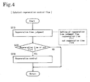
- the catalyst regeneration means 210 is a means for regenerating the direct reduction type NOx catalyst 3 in which the metal M has changed the metal oxide MOx by contacting with NOx to redue NOx to N 2 in the normal operating state of high oxygen concentration where the air/fuel ratio of the exhaust gas is in a lean state.
- the regeneration time judgment means 211 judges the time for performing the regeneration. When it judges that it is the time, the regeneration control means 212 generates the exhaust gas of theoretical air/fuel ratio or a rich state in which the oxygen concentration is almost equal to 0%, and makes the metal oxide MOx contact with reducers such as unburned HC, CO, and H 2 to reduce the metal oxide MOx and to return it to the metal M.
- reducers such as unburned HC, CO, and H 2
- the regeneration time judgment means 211 judges whether it is the regeneration time or not by the NOx concentration Cnox of the exhaust gas downstream of the direct reduction type NOx catalyst 3 when reducing NOx, by the elapsed time during which the oxygen concentration is high, and by the estimated value of the quantity of NOx reduced by the direct reduction type NOx catalyst 3 when reducing NOx.
- the regeneration control means 212 is a means for decreasing the oxygen concentration of the exhaust gas, that is, a means for performing the rich spike operation with the air/fuel ratio Af of 14.7 or less.
- This means 212 performs any one or a combination of the controls such as a fuel injection control for controlling the injection of the fuel to be supplied to the combustion chamber of an internal combustion engine, an intake air control for controlling the quantity of intake air, and an EGR control for controlling the quantity of EGR gas in an EGR system, and performs a feedback control so that the detection value Af is kept within a prescribed set range in accordance with the detection value Af of the air/fuel ratio sensor 6.
- the fuel injection control includes a main injection time control for changing time of the main fuel injection into the combustion chamber of an engine and a post-injection control for performing a post-injection after a main injection.
- the intake air control includes an intake throttle valve control for controlling a valve opening of a not-illustrated intake throttle valve and a turbocharger intake air control for controlling the quantity of an intake air from a compressor of a not-illustrated turbocharger.
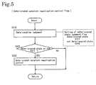
- the deterioration judgment means 221 of the deteriorated catalyst reactivation means 220 relates to the present invention, which is a means for judging the deteriorated state of the direct reduction type NOx catalyst 3 as the decision whether on a reactivation time or not.
- this means 221 is composed of a deterioration zone judgment means 221a, a steady operation judgment means 221b, a decision exhaust gas generation means 221c, and a NOx concentration judgment means 221d.
- the deterioration zone judgment means 221a is a means for judging whether the exhaust gas state is in the zone in which it is capable of performing the decision on catalyst deterioration. This means 221a judges that the exhaust gas state is in the deterioration decision zone when the quantity Qe of the exhaust gas is not more than a prescribed reference quantity Qelim of exhaust gas and a catalyst temperature Tcat ranges between a prescribed lower limit temperature TL for decision and a prescribed upper limit temperature TH for decision.
- the prescribed reference quantity Qelim of exhaust gas is previously set as a value at which the value of a space velocity (SV) to the direct reduction type NOx catalyst 3 becomes a low SV state of 50,000/h or less. Moreover, from experimental results, 250°C is obtained as the prescribed lower limit temperature TL for decision and 350°C is obtained as the prescribed upper limit temperature TH for decision.
- SV space velocity
- the value of the SV is a value obtained by dividing an exhaust gas flow rate by the volume of a catalyst system and serving as a passing velocity.
- the steady operation judgment means 221b is a means for judging whether an engine operating state is of stationary state of an engine. This means 221b judges that the present operation is the steady operation when the absolute value of a change value ⁇ Q of the torque Q is not more than the prescribed reference value ⁇ Qlim and the absolute value of a change value ⁇ Ne of the engine speed Ne is not more than the prescribed reference value ⁇ Nelim.
- the decision exhaust gas generation means 221c is a means for generating an exhaust gas for decision in which the air/fuel ratio Af is approx. 23.
- This means 211c performs feedback control in accordance with the value of the air/fuel ratio Af detected by the air/fuel ratio detector 6 to generate the exhaust gas having a prescribed air/fuel ratio.
- the exhaust gas is generated in accordance with any one of a fuel injection control, an intake air control, and an EGR control or a combination of them.
- the NOx concentration judgment means 221d judges that the direct reduction type NOx catalyst 3 is deteriorated when the NOx concentration Cnox where a state of exhaust gas is in state of the exhaust gas for decision is larger than a prescribed reference value Cnoxlim and returns by setting a deterioration judgment flag F2 to 1. However, when the NOx concentration Cnox is smaller than the prescribed reference value Cnoxlim, the means 221d judges that the catalyst 3 is not deteriorated and returns by setting the deterioration judgment flag F2 to 0.
- the reactivation control means 222 of the deteriorated catalyst reactivation means 220 is a means for reactivating the direct reduction type NOx catalyst 3 deteriorated due to sulfur poisoning. This reactivation is carried by sulfur-purge. This means 222 performs the control for raising the catalyst temperature Tcat to 400°C or higher while bringing an oxygen concentration of the exhaust gas to a value close to 0%.
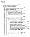
- NOx purging system control flow is described below in which NOx is purged from the exhaust gas by controlling the NOx purging system 10 of above configuration by the NOx purging system control means 200.
- the control flow is performed in accordance with the flowcharts and the like illustrated in FIGs. 3 to 6.
- the NOx purging system control flows illustrated in FIGs. 3 to 6 are designed as a part of the general flow for generally controlling an engine, which is called from a main engine control flow and executed in parallel with an engine control flow. After this control flow is executed, the general flow repeatedly returns to the main engine control flow and is completed in accordance with the completion of the engine control flow.
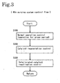
- step S100 the normal operation control for purging NOx by the direct reduction type NOx catalyst 3 is performed for a prescribed period (for example, the time period for judging whether to perform the catalyst regeneration control or the deteriorated catalyst reactivation control) in step S100.
- step S200 as shown by the catalyst regeneration control flow in FIG. 4, it is judged whether the direct reduction type NOx catalyst 3 is in a regeneration time in step S210.
- step S310 it is judged whether the direct reduction type NOx catalyst 3 is deteriorated in step S310.
- the deterioration judgment for the direct reduction type NOx catalyst 3 is performed by the method of deciding on catalyst deterioration based on the deterioration judgment flow illustrated in FIG. 6.
- step S311 the detection and control values showing operation state such as the torque Q and engine speed Ne are first read from the operating state detector 5 in step S311. Then, in step S312, it is judged whether the quantity Qe of the exhaust gas is not more than the prescribed reference quantity Qelim of exhaust gas at which the present state becomes a low SV state in which the value of the space velocity (SV) to the direct reduction type NOx catalyst 3 is 50,000/h or less and the catalyst temperature Tcat ranges between the prescribed lower limit temperature TL (250°C) for decision and the prescribed lower limit temperature TH (350°C) for decision.
- SV space velocity
- step S312 When it is judged in step S312 that an operating state is not in the deterioration decision zone, the flow returns. However, when it is judged that the operating state is in the deterioration decision zone, it is judged in step S313 whether the operating state is in a steady operation state in accordance with whether the absolute value of the change value ⁇ Q of the torque Q is not more than the prescribed reference value ⁇ Qlim and the absolute value of the change value ⁇ Ne of the engine speed Ne is not more than the prescribed reference value ⁇ Nelim.
- step S313 When it is judged that a stationary operation is not currently performed, in step S313, the flow returns. However, when it is judged that the stationary operation is currently performed, the exhaust gas for decision in which the air/fuel ratio is approx. 23 is generated in step S314. And it reads the information of the exhaust gas on values detected by the air/fuel ratio sensor 6 and the NOx sensor 8 in next step S315.
- step S316 it is checked whether the air/fuel ratio Af detected by the air/fuel ratio sensor 6 is in a prescribed air/fuel range, that is, the ratio Af is a value approx. 23 of the exhaust gas for decision.
- the flow returns to step S314 to wait until the Af falls into a prescribed range.
- the flow goes to step S317.
- step S317 it is checked whether the NOx concentration Cnox detected by the NOx sensor 8 is higher than the prescribed reference value Cnoxlim.
- the prescribed reference value Cnoxlim is the data (numerical value or map data) obtained from an experiment, which is previously input to the controller 4.
- step S317 it is judged that the direct reduction type NOx catalyst 3 is deteriorated when the detected NOx concentration Cnox is higher than the reference value Cnoxlim to set the deterioration judgment flag F2 to 1 and the flow returns. However, when lower than the reference value Cnoxlim, it is judged that the catalyst 3 is not deteriorated so set the deterioration judgment flag F2 to 0 and the flow returns.
- the deterioration judgment flag F2 is determined.
- the present invention provides the method of deciding on catalyst deterioration and means for deciding on catalyst deterioration in an exhaust gas purging system capable of properly deciding a deteriorated state of a catalyst due to sulfur poisoning in a NOx purging system using a direct reduction type NOx catalyst to purge the NOx contained in the exhaust gas.
Landscapes
- Engineering & Computer Science (AREA)
- Chemical & Material Sciences (AREA)
- Combustion & Propulsion (AREA)
- General Engineering & Computer Science (AREA)
- Mechanical Engineering (AREA)
- Chemical Kinetics & Catalysis (AREA)
- Health & Medical Sciences (AREA)
- Oil, Petroleum & Natural Gas (AREA)
- General Chemical & Material Sciences (AREA)
- Analytical Chemistry (AREA)
- Environmental & Geological Engineering (AREA)
- Biomedical Technology (AREA)
- Toxicology (AREA)
- Exhaust Gas After Treatment (AREA)
- Electrical Control Of Air Or Fuel Supplied To Internal-Combustion Engine (AREA)
- Combined Controls Of Internal Combustion Engines (AREA)
Claims (4)
- Verfahren zum Entscheiden über die Verschlechterung eines Katalysators in einem NOx-Reinigungssystem, welches einen direkt reduzierenden, in einer Abgasleitung angeordneten NOx-Katalysator aufweist, wobei eine Katalysatorkomponente NOx zu Stickstoff reduziert und auch oxidiert wird, wenn die Sauerstoffkonzentration in dem Abgas eines Motors hoch ist, und die Katalysatorkomponente reduziert wird, wenn die Sauerstoffkonzentration in dem Abgas gering ist, wobei das Verfahren folgendes umfaßt:Erzeugen eines Abgases, um zu entscheiden, wann sich ein Betriebszustand eines Motors innerhalb eines Bereichs zur Entscheidung über die Verschlechterung befindet und in einem stationären Betriebszustand ist, undEntscheiden, daß sich der direkt reduzierende NOx-Katalysator aufgrund einer Schwefelvergiftung verschlechtert, wenn die NOx-Konzentration in dem Abgas, die daraus resultiert, daß das Abgas für die Entscheidung durch den direkt reduzierenden NOx-Katalysator hindurchströmt, nicht kleiner ist als ein vorgeschriebener Referenzwert, wobeidie Entscheidung, daß bzw. ob der Betriebszustand des Motors sich innerhalb eines Bereichs zur Entscheidung über eine Verschlechterung befindet, getroffen wird, wenn die Menge des Abgases nicht größer ist als eine vorgeschriebene Referenzmenge an Abgas und die Katalysatortemperatur im Bereich zwischen einer vorgeschriebenen unteren Grenztemperatur für die Entscheidung und einer vorgeschriebenen oberen Grenztemperatur für die Entscheidung liegt, unddas Abgas für die Entscheidung in einer solchen Weise erzeugt wird, daß das Luft-/Kraftstoff-Verhältnis des Abgases ein Wert ist, der zwischen dem Luft-/Kraftstoff-Verhältnis des Abgases während des normalen Motorbetriebs und dem Luft-/Kraftstoff-Verhältnis des Abgases zum Regenerieren des direkt reduzierenden NOx-Katalysators liegt.
- Verfahren zur Beurteilung der Katalysatorverschlechterung in einem NOx-Reinigungssystem nach Anspruch 1, wobei die vorgeschriebene untere Referenz-Grenztemperatur 250°C beträgt und die vorgeschriebene obere Referenz-Grenztemperatur 350°C beträgt und das Abgas für die Entscheidung ein Luft-/Kraftstoff-Verhältnis von 22 bis 25 hat.
- Vorrichtung zur Entscheidung über die Katalysatorverschlechterung in einem NOx-Reinigungssystem, welches einen direkt reduzierenden, in einer Abgasleitung angeordneten NOx-Katalysator beinhaltet, wobei eine Katalysatorkomponente NOx zu Stickstoff reduziert und auch oxidiert wird, wenn die Sauerstoffkonzentration in dem Abgas eines Motors hoch ist, und die Katalysatorkomponente reduziert wird, wenn die Sauerstoffkonzentration in dem Abgas gering ist, wobei die Vorrichtung folgendes aufweist:eine Vorrichtung zur Beurteilung des Bereichs, um zu beurteilen, ob sich der Zustand eines Abgases in einer Zone bzw. einem Bereich befindet, in der bzw. dem eine Entscheidung über die Katalysatorverschlechterung getroffen werden kann,eine Vorrichtung zur Beurteilung des stationären Betriebs, um zu beurteilen, ob sich der Betriebszustand eines Motors in einem stationären Betriebszustand befindet,eine Vorrichtung zur Erzeugung von Abgas für die Entscheidung, um ein Abgas für die Entscheidung zu erzeugen, undeine Vorrichtung zur Beurteilung der NOx-Konzentration, um zu entscheiden, daß bzw. ob sich der direkt reduzierende NOx-Katalysator verschlechtert hat, wenn die NOx-Konzentration in dem Abgas, die daraus resultiert, daß das Abgas für die Entscheidung durch den direkt reduzierenden NOx-Katalysator hindurchströmt, größer ist als ein vorgeschriebener Referenzwert, wobeidie Vorrichtung zur Beurteilung des Bereichs entscheidet, daß sich der Betriebszustand des Motors innerhalb eines Bereichs zur Entscheidung über die Verschlechterung befindet, wenn die Menge des Abgases nicht größer ist als eine vorgeschriebene Referenzmenge an Abgas und die Katalysatortemperatur im Bereich zwischen einer vorgeschriebenen unteren Grenztemperatur für die Entscheidung und einer vorgeschriebenen oberen Grenztemperatur für die Entscheidung liegt, unddie Vorrichtung zur Erzeugung von Abgas für die Entscheidung das Abgas für die Entscheidung in einer solchen Weise erzeugt, daß das Luft-/Kraftstoff-Verhältnis des Abgases ein Wert ist, der zwischen dem Luft-/Kraftstoff-Verhältnis des Abgases während des normalen Motorbetriebs und dem Luft-/Kraftstoff-Verhältnis des Abgases zum Regenerieren des direkt reduzierenden NOx-Katalysators liegt.
- Vorrichtung zur Beurteilung der Katalysatorverschlechterung in einem oder für ein NOx-Reinigungssystem nach Anspruch 3, wobei die vorgeschriebene untere Referenz-Grenztemperatur 250°C beträgt und die vorgeschriebene obere Referenz-Grenztemperatur 350°C beträgt und das Abgas für die Entscheidung ein Luft-/Kraftstoff-Verhältnis von 22 bis 25 hat.
Applications Claiming Priority (3)
| Application Number | Priority Date | Filing Date | Title |
|---|---|---|---|
| JP2002093884 | 2002-03-29 | ||
| JP2002093884A JP4093302B2 (ja) | 2002-03-29 | 2002-03-29 | NOx浄化システムの触媒劣化判定方法及びNOx浄化システム |
| PCT/JP2003/003938 WO2003083274A1 (en) | 2002-03-29 | 2003-03-28 | METHOD OF DECIDING ON CATALYST DETERIORATION AND MEANS FOR DECIDING ON CATALYST DETERIORATION IN NOx PURGING SYSTEM |
Publications (3)
| Publication Number | Publication Date |
|---|---|
| EP1491737A1 EP1491737A1 (de) | 2004-12-29 |
| EP1491737A4 EP1491737A4 (de) | 2005-08-31 |
| EP1491737B1 true EP1491737B1 (de) | 2006-10-18 |
Family
ID=28671771
Family Applications (1)
| Application Number | Title | Priority Date | Filing Date |
|---|---|---|---|
| EP03745440A Expired - Lifetime EP1491737B1 (de) | 2002-03-29 | 2003-03-28 | VERFAHREN ZUR ERMITTLUNG EINER BEEINTRÄCHTIGUNG DES KATALYSATORS UND MITTEL ZUR ERMITTLUNG DER BEEINTRÄCHTIGUNG EINES KATALYSATORS IN EINEM NOx-SPÜLSYSTEM |
Country Status (5)
| Country | Link |
|---|---|
| US (1) | US20050144933A1 (de) |
| EP (1) | EP1491737B1 (de) |
| JP (1) | JP4093302B2 (de) |
| DE (1) | DE60309149T2 (de) |
| WO (1) | WO2003083274A1 (de) |
Families Citing this family (7)
| Publication number | Priority date | Publication date | Assignee | Title |
|---|---|---|---|---|
| JP3912294B2 (ja) * | 2003-02-19 | 2007-05-09 | トヨタ自動車株式会社 | 内燃機関の排気浄化方法および排気浄化装置 |
| JP4665923B2 (ja) * | 2007-03-13 | 2011-04-06 | トヨタ自動車株式会社 | 触媒劣化判定装置 |
| JP4445002B2 (ja) * | 2007-11-21 | 2010-04-07 | 株式会社日本自動車部品総合研究所 | 排気浄化装置 |
| JP4506874B2 (ja) * | 2008-05-09 | 2010-07-21 | トヨタ自動車株式会社 | 内燃機関の排気浄化装置 |
| SE542464C2 (en) * | 2017-01-16 | 2020-05-12 | Scania Cv Ab | A system and a method for determining a cause for impaired performance of a catalytic configuration |
| US10920645B2 (en) * | 2018-08-02 | 2021-02-16 | Ford Global Technologies, Llc | Systems and methods for on-board monitoring of a passive NOx adsorption catalyst |
| JP7595844B2 (ja) * | 2021-03-31 | 2024-12-09 | マツダ株式会社 | 車両用音生成装置及び車両用音生成方法 |
Family Cites Families (15)
| Publication number | Priority date | Publication date | Assignee | Title |
|---|---|---|---|---|
| JPS62153546A (ja) * | 1985-12-27 | 1987-07-08 | Nippon Denso Co Ltd | エンジンの異常検出装置 |
| JP2861623B2 (ja) * | 1992-05-13 | 1999-02-24 | 日産自動車株式会社 | 内燃機関の触媒劣化診断装置 |
| US5426934A (en) * | 1993-02-10 | 1995-06-27 | Hitachi America, Ltd. | Engine and emission monitoring and control system utilizing gas sensors |
| JP3380366B2 (ja) * | 1995-05-22 | 2003-02-24 | 株式会社日立製作所 | エンジン排気ガス浄化装置の診断装置 |
| JP3852788B2 (ja) * | 1995-10-02 | 2006-12-06 | 株式会社小松製作所 | ディーゼルエンジンのNOx 触媒の劣化検出装置およびその劣化検出方法 |
| JP4092743B2 (ja) * | 1996-07-05 | 2008-05-28 | マツダ株式会社 | エンジンの触媒劣化検出方法およびその装置 |
| US6309536B1 (en) * | 1997-10-14 | 2001-10-30 | Ngk Spark Plug Co., Ltd. | Method and apparatus for detecting a functional condition on an NOx occlusion catalyst |
| US5950421A (en) * | 1997-12-18 | 1999-09-14 | Ford Global Technologies, Inc. | Tungsten-modified platinum NOx traps for automotive emission reduction |
| JP3456401B2 (ja) * | 1998-02-12 | 2003-10-14 | 日産自動車株式会社 | 内燃機関の排気浄化装置 |
| DE19852240A1 (de) * | 1998-11-12 | 2000-05-18 | Volkswagen Ag | Überwachungsverfahren für NOx-Speicherkatalysatoren und Abgasreinigungsvorrichtung zur Durchführung dieses Verfahrens |
| JP2001003735A (ja) * | 1999-06-18 | 2001-01-09 | Hitachi Ltd | エンジン排気浄化装置 |
| US6615580B1 (en) * | 1999-06-23 | 2003-09-09 | Southwest Research Institute | Integrated system for controlling diesel engine emissions |
| EP1337330A2 (de) * | 2000-09-18 | 2003-08-27 | Valtion Teknillinen Tutkimuskeskus | Katalysator und verfahren zur katalytischen reduzierung von stickstoffoxiden |
| JP5134185B2 (ja) * | 2004-08-02 | 2013-01-30 | 本田技研工業株式会社 | 窒素酸化物を接触還元する方法 |
| EP1875954A4 (de) * | 2005-04-11 | 2011-06-22 | Honda Motor Co Ltd | Katalysator zur katalytischen reduktion von stickstoffoxid, katalysatorkonstruktion und verfahren zur katalytischen reduktion von stickstoffoxid |
-
2002
- 2002-03-29 JP JP2002093884A patent/JP4093302B2/ja not_active Expired - Fee Related
-
2003
- 2003-03-28 US US10/504,566 patent/US20050144933A1/en not_active Abandoned
- 2003-03-28 EP EP03745440A patent/EP1491737B1/de not_active Expired - Lifetime
- 2003-03-28 WO PCT/JP2003/003938 patent/WO2003083274A1/ja not_active Ceased
- 2003-03-28 DE DE60309149T patent/DE60309149T2/de not_active Expired - Lifetime
Also Published As
| Publication number | Publication date |
|---|---|
| EP1491737A4 (de) | 2005-08-31 |
| DE60309149D1 (de) | 2006-11-30 |
| WO2003083274A1 (en) | 2003-10-09 |
| DE60309149T2 (de) | 2007-08-30 |
| JP4093302B2 (ja) | 2008-06-04 |
| EP1491737A1 (de) | 2004-12-29 |
| JP2003286830A (ja) | 2003-10-10 |
| US20050144933A1 (en) | 2005-07-07 |
Similar Documents
| Publication | Publication Date | Title |
|---|---|---|
| EP1491735B1 (de) | Abgasentgiftungssystem und verfahren zu dessen steuerung | |
| JP4415648B2 (ja) | サルファパージ制御方法及び排気ガス浄化システム | |
| EP2034149A1 (de) | Abgasreinigungsvorrichtung und diese verwendendes abgasreinigungsverfahren | |
| EP2460999B1 (de) | Verfahren zur Vorhersage der SOx-Beladung eines DeNOx-Katalysators und dieses verwendende Abgassystem | |
| US7168242B2 (en) | NOx catalyst regeneration method for NOx purifying system and NOx purifying system | |
| US20050144934A1 (en) | Nox purging system and method of reactivating deteriorated catalyst therein | |
| JP5771634B2 (ja) | 火花点火式内燃機関用の排気機構 | |
| EP1491737B1 (de) | VERFAHREN ZUR ERMITTLUNG EINER BEEINTRÄCHTIGUNG DES KATALYSATORS UND MITTEL ZUR ERMITTLUNG DER BEEINTRÄCHTIGUNG EINES KATALYSATORS IN EINEM NOx-SPÜLSYSTEM | |
| JP4686547B2 (ja) | 排気ガス浄化を伴う機関駆動車両 | |
| EP1655462B1 (de) | Mechanische Vorrichtung mit NOx Speicher- und Umsetzungkalalysator | |
| EP3098423B1 (de) | Steuerungsvorrichtung für einen verbrennungsmotor | |
| JP2005194927A (ja) | 排気ガス浄化方法及び排気ガス浄化システム | |
| JP2007046494A (ja) | 内燃機関の空燃比制御装置 | |
| JP2006152947A (ja) | 排気ガス浄化システムの脱硫制御方法及び排気ガス浄化システム | |
| JP2003500595A (ja) | Nox吸収触媒の再生を制御する方法 | |
| JP2010196496A (ja) | 排気浄化装置 | |
| US10519840B2 (en) | Abnormality diagnosis system for exhaust gas purification apparatus | |
| JP2010024957A (ja) | 内燃機関の排気浄化装置 | |
| JP2003293744A (ja) | 内燃機関の排気浄化装置 | |
| KR20220006310A (ko) | 배출 가스 정화 장치 및 그 제어 방법 | |
| KR20200044414A (ko) | 자동차의 배기가스 정화장치 및 그 제어방법 | |
| JP2011027010A (ja) | 内燃機関の排気浄化装置 | |
| JP2006002641A (ja) | 排気ガス浄化方法及び排気ガス浄化システム | |
| JP2005248891A (ja) | 排気ガス浄化方法及び排気ガス浄化システム | |
| JP2016125463A (ja) | 排気浄化装置 |
Legal Events
| Date | Code | Title | Description |
|---|---|---|---|
| PUAI | Public reference made under article 153(3) epc to a published international application that has entered the european phase |
Free format text: ORIGINAL CODE: 0009012 |
|
| 17P | Request for examination filed |
Effective date: 20040819 |
|
| AK | Designated contracting states |
Kind code of ref document: A1 Designated state(s): AT BE BG CH CY CZ DE DK EE ES FI FR GB GR HU IE IT LI LU MC NL PT RO SE SI SK TR |
|
| A4 | Supplementary search report drawn up and despatched |
Effective date: 20050714 |
|
| RIC1 | Information provided on ipc code assigned before grant |
Ipc: 7B 01D 53/94 B Ipc: 7F 01N 3/08 B Ipc: 7F 01N 3/20 A Ipc: 7F 01N 11/00 B |
|
| GRAP | Despatch of communication of intention to grant a patent |
Free format text: ORIGINAL CODE: EPIDOSNIGR1 |
|
| GRAS | Grant fee paid |
Free format text: ORIGINAL CODE: EPIDOSNIGR3 |
|
| GRAA | (expected) grant |
Free format text: ORIGINAL CODE: 0009210 |
|
| AK | Designated contracting states |
Kind code of ref document: B1 Designated state(s): DE FR GB IT |
|
| REG | Reference to a national code |
Ref country code: GB Ref legal event code: FG4D |
|
| REF | Corresponds to: |
Ref document number: 60309149 Country of ref document: DE Date of ref document: 20061130 Kind code of ref document: P |
|
| ET | Fr: translation filed | ||
| PLBE | No opposition filed within time limit |
Free format text: ORIGINAL CODE: 0009261 |
|
| STAA | Information on the status of an ep patent application or granted ep patent |
Free format text: STATUS: NO OPPOSITION FILED WITHIN TIME LIMIT |
|
| 26N | No opposition filed |
Effective date: 20070719 |
|
| PGFP | Annual fee paid to national office [announced via postgrant information from national office to epo] |
Ref country code: IT Payment date: 20090321 Year of fee payment: 7 |
|
| PGFP | Annual fee paid to national office [announced via postgrant information from national office to epo] |
Ref country code: FR Payment date: 20100324 Year of fee payment: 8 |
|
| PGFP | Annual fee paid to national office [announced via postgrant information from national office to epo] |
Ref country code: GB Payment date: 20100322 Year of fee payment: 8 |
|
| PGFP | Annual fee paid to national office [announced via postgrant information from national office to epo] |
Ref country code: DE Payment date: 20100429 Year of fee payment: 8 |
|
| PG25 | Lapsed in a contracting state [announced via postgrant information from national office to epo] |
Ref country code: IT Free format text: LAPSE BECAUSE OF NON-PAYMENT OF DUE FEES Effective date: 20100328 |
|
| GBPC | Gb: european patent ceased through non-payment of renewal fee |
Effective date: 20110328 |
|
| REG | Reference to a national code |
Ref country code: FR Ref legal event code: ST Effective date: 20111130 |
|
| PG25 | Lapsed in a contracting state [announced via postgrant information from national office to epo] |
Ref country code: DE Free format text: LAPSE BECAUSE OF NON-PAYMENT OF DUE FEES Effective date: 20111001 Ref country code: FR Free format text: LAPSE BECAUSE OF NON-PAYMENT OF DUE FEES Effective date: 20110331 |
|
| REG | Reference to a national code |
Ref country code: DE Ref legal event code: R119 Ref document number: 60309149 Country of ref document: DE Effective date: 20111001 |
|
| PG25 | Lapsed in a contracting state [announced via postgrant information from national office to epo] |
Ref country code: GB Free format text: LAPSE BECAUSE OF NON-PAYMENT OF DUE FEES Effective date: 20110328 |