EP1495876A1 - Emballage pour support d'impression et méthode de son utilisation - Google Patents
Emballage pour support d'impression et méthode de son utilisation Download PDFInfo
- Publication number
- EP1495876A1 EP1495876A1 EP04002953A EP04002953A EP1495876A1 EP 1495876 A1 EP1495876 A1 EP 1495876A1 EP 04002953 A EP04002953 A EP 04002953A EP 04002953 A EP04002953 A EP 04002953A EP 1495876 A1 EP1495876 A1 EP 1495876A1
- Authority
- EP
- European Patent Office
- Prior art keywords
- wrapper
- print media
- media
- tab
- Prior art date
- Legal status (The legal status is an assumption and is not a legal conclusion. Google has not performed a legal analysis and makes no representation as to the accuracy of the status listed.)
- Withdrawn
Links
- 238000000034 method Methods 0.000 title claims description 29
- 238000004806 packaging method and process Methods 0.000 claims description 14
- 239000004033 plastic Substances 0.000 claims description 5
- 230000008878 coupling Effects 0.000 claims 1
- 238000010168 coupling process Methods 0.000 claims 1
- 238000005859 coupling reaction Methods 0.000 claims 1
- 238000004519 manufacturing process Methods 0.000 description 7
- 238000003780 insertion Methods 0.000 description 3
- 230000037431 insertion Effects 0.000 description 3
- 238000012986 modification Methods 0.000 description 3
- 230000004048 modification Effects 0.000 description 3
- 238000010586 diagram Methods 0.000 description 2
- 230000004069 differentiation Effects 0.000 description 2
- 239000000853 adhesive Substances 0.000 description 1
- 230000001070 adhesive effect Effects 0.000 description 1
- 230000015572 biosynthetic process Effects 0.000 description 1
- 239000000284 extract Substances 0.000 description 1
- 239000003000 extruded plastic Substances 0.000 description 1
- 238000009434 installation Methods 0.000 description 1
- 230000002452 interceptive effect Effects 0.000 description 1
- 239000000463 material Substances 0.000 description 1
- 230000003287 optical effect Effects 0.000 description 1
- 238000004064 recycling Methods 0.000 description 1
Images





Classifications
-
- B—PERFORMING OPERATIONS; TRANSPORTING
- B41—PRINTING; LINING MACHINES; TYPEWRITERS; STAMPS
- B41J—TYPEWRITERS; SELECTIVE PRINTING MECHANISMS, i.e. MECHANISMS PRINTING OTHERWISE THAN FROM A FORME; CORRECTION OF TYPOGRAPHICAL ERRORS
- B41J13/00—Devices or arrangements of selective printing mechanisms, e.g. ink-jet printers or thermal printers, specially adapted for supporting or handling copy material in short lengths, e.g. sheets
- B41J13/0081—Sheet-storing packages, e.g. for protecting the sheets against ambient influences, e.g. light, humidity, changes in temperature
Definitions
- An important step in the production of a printed image on a print media is the feeding of a print media into a printing device.
- a number of methods have been developed to facilitate the introduction of print media into printing devices including: incorporating perforated paper, continuous feed fan-fold paper, various containment structures, etc.
- a recent trend has developed eliciting the ability to form images on numerous different media types. These different media types include envelopes, transparencies, card stock paper, and regular letter paper. These different media types are packaged in large quantities called reams so as to provide a convenient amount of media to a printing device.
- a media wrapper for use in a printing device includes a first end, a second end, and a perforation disposed between the first and second ends, wherein the perforation is configured to split the media wrapper separating the first and second ends.
- Fig. 1 illustrates a ream of print media according to one exemplary embodiment.
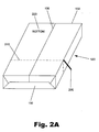
- Fig. 2A is a perspective view of a ream of print media including a tear away portion according to one exemplary embodiment.
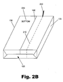
- Fig. 2B is a perspective view of a ream of print media including a landscape tear away portion according to one exemplary embodiment.
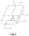
- Fig. 3 is a perspective view of a ream of media illustrating an exposed section of media according to one exemplary embodiment.
- Fig. 4 is a perspective view of a ream of print media indicating a location where a pick-up mechanism of a document printing device may contact the print media according to one exemplary embodiment.
- Fig. 5 is a schematic view of a print media incorporated in a printing device according to one exemplary embodiment.
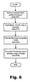
- Fig. 6 is a flow chart depicting a method for using a print media with a partial wrapper in a printing device according to one exemplary embodiment.
- Fig. 7 is a perspective view of a ream of print media illustrating an alternative embodiment.
- Fig. 8 is a perspective view of a ream of print media illustrating yet another alternative embodiment.
- Fig. 9 is a cross-sectional view of a printing device incorporating a plurality of print media reams according to one exemplary embodiment.
- print media wrapper A system and a method for packaging a print media to increase convenience to the user when loading the print media in a printing device are presented below. More specifically, a print media wrapper is described that allows for a partial removal of the wrapper, thereby exposing print media to a pickup mechanism of a printing device while maintaining organizational support to the print media.
- print media is meant to be understood, both here and in the appended claims, as any object that may be packaged in a ream format to facilitate its reception by a printing apparatus including, but in no way limited to, envelopes, card stock, transparencies, labels, paper, or optical disks (compact disks or digital video disks).
- the present print media packaging system will be described herein, for ease of explanation only, in the context of a ream of paper configured to be introduced to a printer.
- the present print media wrapper may be used with the above-mentioned print media and may similarly be incorporated in any number of printing devices including, but in no way limited to, printers, copiers, scanners, or facsimile machines.
- a typical print media wrapper (120) may include a seam (100) and a plurality of end portions (130).
- the seam (100) may, according to manufacturing specifications, indicate the bottom side (110) of the ream of print media contained therein.
- the seam (100) illustrated in Figure 1 may be used to distinguish which side of the ream should be up or down as dictated by the nap of the print media.
- the nap of a print media refers to differing surface textures of opposing print media surfaces.
- This side differentiation is often referred to as the nap of the paper.
- the wrapper (120) of a ream of media, by way of the seam (100) of the wrapper (120), may indicate the nap of the print media.
- a distinguishing label (220; Fig.
- FIG. 2A illustrates an exemplary embodiment of a system and a method for removing only a portion of a print media wrapper (120) prior to its insertion into a printing device.
- a pull-tab (200) such as an extruded plastic ribbon, may be employed along a slot-cut or perforated seam (210) that runs perpendicular to the wrapper seam (100).
- the pull-tab (200) When the pull-tab (200) is pulled, the tab may traverse the perforated seam (210) causing a somewhat precise split in the print media wrapper (120). With the print media wrapper (120) being split along the perforated seam (210), a portion of the print media wrapper (120) may then be easily removed.
- any type of pull tab that is structurally sufficient to tear the print media wrapper (120) along the perforated seam (210) may be incorporated including, but in no way limited to, a string, a plastic ribbon, or a ribbon of a heavier paper than that of the print media wrapper (120).
- the print media wrapper may be manufactured according to a number of methods.
- the perforated seam (210) may be formed in the print media wrapper (120) prior to wrapping the ream of print media.
- the pull-tab (200) may be disposed on the print media wrapper.
- the pull-tab (200) may either be coupled to the print media wrapper (120) with an adhesive or it may be positioned around the print media ream prior to assembly. Once assembled, the pull-tab (200) may be positioned along the perforated seam (210) such that the pull-tab (200) is externally accessible to the user as illustrated in Figure 2A.
- Figure 2B illustrates another exemplary embodiment of the present system for removing only a portion of a print media wrapper (120).
- the perforated seam (210) may be disposed parallel to the wrapper seam (100).
- a somewhat precise split may be formed lengthwise on the print media wrapper (120) allowing for the removal of a portion of the print media wrapper.
- a landscaped orientation of print media may be exposed.
- Figures 2A and 2B illustrate alternative orientations of the perforated seam (210), any orientation may be incorporated according to the present system to accommodate the media retrieval methods of various printing devices.
- the perforated seam (210; Fig. 2A) and the pull-tab (200; Fig. 2A) may be positioned such that when they are implemented, a portion of the print media wrapper (120) may be removed to expose a sufficient amount of the print media "X" (300) to be picked up by a pick-up mechanism of the document producing device (not shown).
- the amount of print media exposed (300), equal to the distance from the edge of the newly exposed media (310) to the remaining portion of the print media wrapper (120), may be sufficient for a pick up mechanism of a printing device to contact and remove a single unit of media without contacting the print media wrapper (120). Contact between the pick up mechanism and the print media wrapper (120) may prevent or disrupt the function of the pick-up mechanism.
- Removing only the least acceptable amount of print media wrapper (120) from the ream of print media necessary to avoid contact between the print media wrapper (120) and the pick up mechanism of a printing device will provide a maximum ease of loading the print media to the user.
- a maximum amount of print media wrapper may remain around the print media providing organizational support as well as indicating the nap of the print media. This print media wrapper will allow a user to load the print media into a tray or cassette of a printing device without a disheveling of the media.
- the remaining print media wrapper (120) may also display information to a user without necessitating a removal of the print media.
- the remaining print media may include a tag or a label (not shown) that indicates print media qualities including, but in no way limited to, the quality, the color, the type, the brightness, the manufacturer, the recycling content, and/or the texture of the media contained therein.
- the tag or label may remain on the print media wrapper (120) and be visible to a user after its installation in a printing device. The tag may then aid in providing the user with print media information without having to disrupt the image forming process.
- Figure 4 illustrates one of the many different sites (400) where a pick-up mechanism may contact a ream of exposed print media (310) to remove a single unit of print media.
- the site (400) must be exposed from the wrapper (120) in order for the pick-up mechanism to function properly.
- the site (400) illustrating where the pick-up mechanism may contact the ream of exposed print media (310) is only exemplary and may vary in location to any point on the exposed print media (310) as dictated by the specific printing device being used.
- Figure 5 is a diagram of a printing device (500) incorporating the present print media wrapper (120; Fig. 2).
- print media (520) may be inserted into a tray or cassette (530) of a printing device (500).
- the print media (520) may, as discussed above, be exposed to a pick-up mechanism (510) of the printing device (500) on one end and contained by a print media wrapper (120) on the other end.
- the diagram of Figure 5 shows that a sufficient amount (300; Fig. 3) of print media wrapper (120) has been removed from the ream of print media exposing a sufficient amount of print media for the pick-up mechanism (510) of the printing device (500) to retrieve a unit of print media from the tray (530).
- the pick-up mechanism (510) retrieves one unit of print media from the stack (520) and pulls it into the printing device (500) in order to attach an intended image onto the single unit of print media.
- the pick-up mechanism (510) does not hinder the print media retrieval process. Rather, by maintaining a portion of the print media wrapper (120) on the print media throughout the printing process, the media in a stack (520) is more secure. Additionally, the remaining portion of print media wrapper (120) aides the user by facilitating the removal from and insertion to the printing device (500) of either a full or partially depleted ream of print media. Removal and insertion are facilitated by the remaining portion of the print media wrapper because the remaining print media wrapper (120) keeps the print media in a single stack preventing it from becoming disheveled. This allows a partially depleted ream of print media to be removed from a document printing device (500) and to be temporarily replaced by a different print media type, if a print job so requires.
- Figure 6 is a flow chart illustrating how a user would go about producing a document in a printing device (500; Fig. 5) using media bound by the present print media wrapper.
- a user would begin by removing a portion of the print media wrapper (120; Fig. 2) from the ream of print media (step 600).
- the amount of print media wrapper (120; Fig. 2) removed from the ream of print media may be predetermined by the location of the perforated seam (210; Fig. 2).
- the splitting of the perforated seam may be performed by a pull tab (200; Fig. 2), as described above, or by any other sufficient removal device.
- a piece of the print media wrapper corresponding to the side of the print media that will be introduced to the pick-up roller may be removed and discarded.
- the print media may be inserted into a tray or cassette of the printing device (step 610).
- the remaining print media wrapper (120; Fig. 2) will provide organizational support to the ream of print media while it is being inserted into a tray or cassette of the printing device (500; Fig. 5).
- the print media may be inserted into the tray or cassette by placing the side of the print media wrapper having a seam (100; Fig. 2) down in the tray or cassette if doing so will comply with the nap conditions discussed previously.
- the tray or cassette of the printing device may then be secured to the printing device to enable the document production process.
- a pick-up mechanism (510; Fig. 5) may come into contact with and retrieve a required amount of print media from the tray or cassette (step 620). As shown in Figure 5, the pick-up mechanism (510) contacts the exposed print media (520) without contacting the remaining print media wrapper (120). This allows the print media wrapper to remain in the tray or cassette (530) and to provide support to the print media without interfering with the media picking process.
- the pick-up mechanism may then provide the print media to the printing device where a desired image may be secured to the print media producing a desired image (step 630; Fig. 6).
- the empty print media wrapper (120) may then be removed from the tray or cassette (530) and a new ream of print media and its wrapper placed in its stead.
- a tab (700) may be formed as an integral part of the print media wrapper (120) just below the perforated seam (210).
- the tab (700) may be of the same material as the print media wrapper (120) or it may be a reinforced tab formed during the production of the print media wrapper.
- the integral tab (700) when a user desires to remove a portion of the print media wrapper (120), the integral tab (700) may be pulled, causing a tear of the print media wrapper to occur along a perforated seam (210). This tear may effectively separate a portion of the print media wrapper so that a pick-up mechanism (510; Fig. 5) may access the print media contained therein.
- Figure 8 illustrates yet another alternative embodiment of the present print media wrapper (120).
- no tab 700; Fig. 7 or pull tab (200; Fig. 2) may be formed with the print media wrapper.
- a perforated seam (210) may be disposed on the print media wrapper (120) to facilitate the removal of a predetermined portion of the print media wrapper (120).
- a user may use their hand or any other object to tear or rip the print media wrapper (120) along the perforated seam (210) thereby exposing a portion of print media.
- the print media wrapper (120) is removed sufficiently to expose the print media to a pick up mechanism (510; Fig. 5), the ream of print media may be inserted in the printing device as explained above.
- Figure 9 illustrates an alternative embodiment showing a printing device (500) including a high-capacity input tray (900) having a media tray (920) disposed on a biasing apparatus (910).
- the biasing apparatus (910) illustrated in Figure 9 may be any biasing apparatus configured to implement a translational force on the media tray (920) including, but in no way limited to, a spring.
- multiple reams of print media having a portion of the print media wrapper (120) removed so as to expose a portion of the print media (520) may be stacked on the media tray (920).
- the biasing apparatus (910) may translate the media tray (920) and subsequently the exposed print media toward the pick up roller (510) to maintain a necessary contact pressure between the pick up roller and the exposed print media (520).
- the empty print media wrapper (120) may be forced upward and compressed by both the media tray (920) and the un-exhausted reams of print media.
- multiple reams of print media may be loaded in a single printing device while maintaining a portion of the print media wrapper on the print media for the reasons mentioned above.
- the present print media wrapper provides adequate access to a ream of print media by a pick-up mechanism while simultaneously providing organizational support to the print media. Moreover, by allowing a portion of the print media wrapper to remain on the print media, a user is able to speedily position the print media such that the desired image is printed on the best surface according to the nap of the print medium.
Landscapes
- Sheets, Magazines, And Separation Thereof (AREA)
- Packages (AREA)
- Packaging Of Annular Or Rod-Shaped Articles, Wearing Apparel, Cassettes, Or The Like (AREA)
Applications Claiming Priority (2)
| Application Number | Priority Date | Filing Date | Title |
|---|---|---|---|
| US615677 | 2003-07-08 | ||
| US10/615,677 US7165675B2 (en) | 2003-07-08 | 2003-07-08 | Media wrapper and method of using the same |
Publications (1)
| Publication Number | Publication Date |
|---|---|
| EP1495876A1 true EP1495876A1 (fr) | 2005-01-12 |
Family
ID=33452664
Family Applications (1)
| Application Number | Title | Priority Date | Filing Date |
|---|---|---|---|
| EP04002953A Withdrawn EP1495876A1 (fr) | 2003-07-08 | 2004-02-10 | Emballage pour support d'impression et méthode de son utilisation |
Country Status (4)
| Country | Link |
|---|---|
| US (2) | US7165675B2 (fr) |
| EP (1) | EP1495876A1 (fr) |
| JP (1) | JP2005029267A (fr) |
| CN (1) | CN1576178A (fr) |
Cited By (1)
| Publication number | Priority date | Publication date | Assignee | Title |
|---|---|---|---|---|
| EP1683748A1 (fr) * | 2005-01-24 | 2006-07-26 | Frama Ag | Dispositif pour séparer des étiquettes empilées dans un dispositif d'alimentation |
Families Citing this family (8)
| Publication number | Priority date | Publication date | Assignee | Title |
|---|---|---|---|---|
| US7849904B2 (en) | 2004-03-10 | 2010-12-14 | Coating Excellence International, Inc. | Tear tape applicator for ream wrap and other packaging materials |
| US20050202191A1 (en) * | 2004-03-10 | 2005-09-15 | Nowak Michael R. | Ream wrap packaging with tear tapes |
| GB0515335D0 (en) * | 2005-07-26 | 2005-08-31 | Innovia Films Ltd | Easy open ream wrap |
| FI20065711A7 (fi) * | 2006-11-10 | 2008-05-11 | Upm Kymmene Corp | Arkkimateriaalin, kuten paperin pakkaus |
| FI20065712A7 (fi) * | 2006-11-10 | 2008-05-11 | Upm Kymmene Corp | Paperiarkkien pakkaus |
| US7789291B2 (en) * | 2008-06-10 | 2010-09-07 | Printpack Illinois, Inc. | Packaging article and method with particular tearing slit arrangement |
| US7886904B1 (en) * | 2009-07-30 | 2011-02-15 | Owens Corning Intellectual Capital, Llc | Loosefill package for blowing wool machine |
| US10239677B2 (en) | 2015-07-29 | 2019-03-26 | Sonoco Development, Inc. | Easy-open media wrapper |
Citations (4)
| Publication number | Priority date | Publication date | Assignee | Title |
|---|---|---|---|---|
| US3367487A (en) * | 1967-05-03 | 1968-02-06 | Kimberly Clark Co | Bulk package for cut size paper |
| US3767188A (en) * | 1971-05-24 | 1973-10-23 | Burt & Co F N | Paper feeding device |
| EP1099639A1 (fr) * | 1999-11-11 | 2001-05-16 | Seiko Epson Corporation | Emballage de feuilles séparées at appareil de formation d'images |
| US20020136575A1 (en) * | 2001-03-23 | 2002-09-26 | Cornelius William L. | Imaging media handling package |
Family Cites Families (26)
| Publication number | Priority date | Publication date | Assignee | Title |
|---|---|---|---|---|
| US2706076A (en) * | 1953-10-12 | 1955-04-12 | Waldorf Paper Products Co | Container opener |
| US3302851A (en) * | 1965-03-15 | 1967-02-07 | Waldorf Paper Prod Co | Shipping folder for books and similar objects |
| US3441195A (en) * | 1967-10-10 | 1969-04-29 | Hoerner Waldorf Corp | Book folder |
| US3465946A (en) * | 1967-10-26 | 1969-09-09 | Hoerner Waldorf Corp | Recessed end containers |
| US3987902A (en) * | 1974-05-31 | 1976-10-26 | Billy Burgess | Package inspection apparatus |
| US4011155A (en) * | 1975-03-31 | 1977-03-08 | Pemco, Inc. | Wrapped package inspection and rejection apparatus |
| US4015770A (en) * | 1975-07-24 | 1977-04-05 | Tamarin Bernard J | Packaging |
| GB2123376B (en) * | 1982-07-12 | 1985-09-11 | Tdk Electronics Co Ltd | Tear-open package |
| US5053814A (en) * | 1986-12-24 | 1991-10-01 | Minolta Camera Kabushiki Kaisha | Image forming apparatus |
| GB2206555B (en) * | 1987-07-10 | 1991-11-20 | Xerox Corp | Wrapper with tear strip |
| US5137269A (en) * | 1989-06-29 | 1992-08-11 | Minolta Camera Kabushiki Kaisha | Sheet package and sheet feeding apparatus designed to employ same |
| US5158499A (en) * | 1990-07-09 | 1992-10-27 | American National Can Company | Laser scoring of packaging substrates |
| JP2732975B2 (ja) | 1992-02-06 | 1998-03-30 | シャープ株式会社 | 開封方法およびその開封装置 |
| JP3093431B2 (ja) * | 1992-04-30 | 2000-10-03 | 株式会社リコー | 画像形成装置の給紙装置 |
| US5510165A (en) * | 1992-06-30 | 1996-04-23 | Sony Corporation | Thin film wrapping for cassette case |
| EP0577509B1 (fr) * | 1992-06-30 | 1996-11-13 | Sony Corporation | Procédé d'empaquetage d'un boîtier de cassette dans un film mince |
| JP3235227B2 (ja) * | 1992-10-30 | 2001-12-04 | ソニー株式会社 | オーバラップフィルム及びオーバラップフィルムを用いたラッピング方法 |
| US6006907A (en) * | 1993-04-01 | 1999-12-28 | Fuji Photo Film Co., Ltd. | Wrapped article |
| US5989724A (en) * | 1993-05-10 | 1999-11-23 | International Paper Company | Recyclable and repulpable ream wrap and related methods of manufacture |
| JP3368010B2 (ja) | 1993-10-01 | 2003-01-20 | 株式会社リコー | 給紙装置 |
| EP0745540A1 (fr) * | 1995-06-02 | 1996-12-04 | Fabriques De Tabac Reunies S.A. | Feuille d'emballage, paquet de cigarettes fabriqué à partir de celle-ci |
| US6598795B1 (en) * | 2000-04-24 | 2003-07-29 | Hewlett-Packard Development Company, Lp | Use of bar code to specify media type in an imaging device |
| US20020004732A1 (en) * | 2000-05-09 | 2002-01-10 | Quigg William Donovan | System and method for coordinating production and distribution of paper products packaged with promotional materials |
| JP4707163B2 (ja) * | 2000-05-24 | 2011-06-22 | 有限会社エフ・アンド・エフ | パッケージ材およびパッケージされた用紙 |
| US6536968B2 (en) * | 2000-12-01 | 2003-03-25 | Hewlett-Packard Company | Paper tray for a printer |
| JP2003095456A (ja) | 2001-09-26 | 2003-04-03 | Kyocera Mita Corp | 給紙装置,画像形成装置及び給紙パッケージ |
-
2003
- 2003-07-08 US US10/615,677 patent/US7165675B2/en not_active Expired - Fee Related
-
2004
- 2004-02-10 EP EP04002953A patent/EP1495876A1/fr not_active Withdrawn
- 2004-07-06 JP JP2004199204A patent/JP2005029267A/ja not_active Withdrawn
- 2004-07-08 CN CNA2004100635152A patent/CN1576178A/zh active Pending
-
2006
- 2006-08-25 US US11/467,248 patent/US8627638B2/en not_active Expired - Fee Related
Patent Citations (4)
| Publication number | Priority date | Publication date | Assignee | Title |
|---|---|---|---|---|
| US3367487A (en) * | 1967-05-03 | 1968-02-06 | Kimberly Clark Co | Bulk package for cut size paper |
| US3767188A (en) * | 1971-05-24 | 1973-10-23 | Burt & Co F N | Paper feeding device |
| EP1099639A1 (fr) * | 1999-11-11 | 2001-05-16 | Seiko Epson Corporation | Emballage de feuilles séparées at appareil de formation d'images |
| US20020136575A1 (en) * | 2001-03-23 | 2002-09-26 | Cornelius William L. | Imaging media handling package |
Cited By (2)
| Publication number | Priority date | Publication date | Assignee | Title |
|---|---|---|---|---|
| EP1683748A1 (fr) * | 2005-01-24 | 2006-07-26 | Frama Ag | Dispositif pour séparer des étiquettes empilées dans un dispositif d'alimentation |
| US8167018B2 (en) | 2005-01-24 | 2012-05-01 | Frama Ag | Device for separating labels stacked in a feeder |
Also Published As
| Publication number | Publication date |
|---|---|
| CN1576178A (zh) | 2005-02-09 |
| US20070000661A1 (en) | 2007-01-04 |
| US8627638B2 (en) | 2014-01-14 |
| JP2005029267A (ja) | 2005-02-03 |
| US20050006265A1 (en) | 2005-01-13 |
| US7165675B2 (en) | 2007-01-23 |
Similar Documents
| Publication | Publication Date | Title |
|---|---|---|
| EP1196290B1 (fr) | Utilisation du code a barres pour indiquer le type de support dans un dispositif d'imagerie | |
| EP1091854B1 (fr) | Procedes relatifs a une feuille haute resistance, flexible, pliable et imprimable | |
| US8627638B2 (en) | Method of packaging media used in a document producing device | |
| EP0768566A2 (fr) | Dispositif pour la protection de papier pour l'impression | |
| WO2001089957A1 (fr) | Materiau d'emballage et feuilles de papier emballees | |
| US7597315B2 (en) | Sheet package including side parts for a printer | |
| US7726646B2 (en) | Sheet package with recloseable flap | |
| US6945527B2 (en) | High capacity media apparatus and method | |
| US6311970B1 (en) | Paper feed cassette and image formation apparatus | |
| JP2009062121A (ja) | 画像形成装置、記録媒体取分部材 | |
| JPS6061438A (ja) | 給紙装置 | |
| EP0355422A2 (fr) | Feuille à format réductible | |
| JP2001080772A (ja) | シート給送装置 | |
| JPH1179428A (ja) | 給紙用カセット | |
| JPWO2002100748A1 (ja) | 記録媒体パッケージ | |
| JPH04243742A (ja) | 記録装置 | |
| JP2003192209A (ja) | スタッカー付きプリンター | |
| JP2007245679A (ja) | 孔版印刷用原紙および孔版印刷装置 | |
| JP2004059225A (ja) | 用紙パッケージ | |
| JPS61238629A (ja) | 摩擦分離手段を備える給紙装置 | |
| JPH0522436U (ja) | フアクシミリ装置 | |
| JP2001310831A (ja) | シート梱包部材及びシートパック及びシート載置装置及び画像形成装置及びシートパックの載置方法 | |
| JPS6077057A (ja) | 伝票作成装置 | |
| JP2006137575A (ja) | プリンタ | |
| JPH04338037A (ja) | 自動給紙機構 |
Legal Events
| Date | Code | Title | Description |
|---|---|---|---|
| PUAI | Public reference made under article 153(3) epc to a published international application that has entered the european phase |
Free format text: ORIGINAL CODE: 0009012 |
|
| AK | Designated contracting states |
Kind code of ref document: A1 Designated state(s): AT BE BG CH CY CZ DE DK EE ES FI FR GB GR HU IE IT LI LU MC NL PT RO SE SI SK TR |
|
| AX | Request for extension of the european patent |
Extension state: AL LT LV MK |
|
| 17P | Request for examination filed |
Effective date: 20050523 |
|
| AKX | Designation fees paid |
Designated state(s): CH DE FR GB LI NL SE |
|
| STAA | Information on the status of an ep patent application or granted ep patent |
Free format text: STATUS: THE APPLICATION HAS BEEN WITHDRAWN |
|
| 18W | Application withdrawn |
Effective date: 20061016 |