EP1496576B1 - Dispositif de connexion électrique avec une ligne d'alimentation en énergie pour moyenne et haute tension ainsi que procédé de fabrication d'une partie isolante d'un tel dispositif - Google Patents
Dispositif de connexion électrique avec une ligne d'alimentation en énergie pour moyenne et haute tension ainsi que procédé de fabrication d'une partie isolante d'un tel dispositif Download PDFInfo
- Publication number
- EP1496576B1 EP1496576B1 EP04016065A EP04016065A EP1496576B1 EP 1496576 B1 EP1496576 B1 EP 1496576B1 EP 04016065 A EP04016065 A EP 04016065A EP 04016065 A EP04016065 A EP 04016065A EP 1496576 B1 EP1496576 B1 EP 1496576B1
- Authority
- EP
- European Patent Office
- Prior art keywords
- contact part
- insulating part
- contact
- insulating
- thermoplastic plastic
- Prior art date
- Legal status (The legal status is an assumption and is not a legal conclusion. Google has not performed a legal analysis and makes no representation as to the accuracy of the status listed.)
- Revoked
Links
Images


Classifications
-
- B—PERFORMING OPERATIONS; TRANSPORTING
- B29—WORKING OF PLASTICS; WORKING OF SUBSTANCES IN A PLASTIC STATE IN GENERAL
- B29C—SHAPING OR JOINING OF PLASTICS; SHAPING OF MATERIAL IN A PLASTIC STATE, NOT OTHERWISE PROVIDED FOR; AFTER-TREATMENT OF THE SHAPED PRODUCTS, e.g. REPAIRING
- B29C45/00—Injection moulding, i.e. forcing the required volume of moulding material through a nozzle into a closed mould; Apparatus therefor
- B29C45/14—Injection moulding, i.e. forcing the required volume of moulding material through a nozzle into a closed mould; Apparatus therefor incorporating preformed parts or layers, e.g. injection moulding around inserts or for coating articles
- B29C45/14639—Injection moulding, i.e. forcing the required volume of moulding material through a nozzle into a closed mould; Apparatus therefor incorporating preformed parts or layers, e.g. injection moulding around inserts or for coating articles for obtaining an insulating effect, e.g. for electrical components
-
- H—ELECTRICITY
- H01—ELECTRIC ELEMENTS
- H01R—ELECTRICALLY-CONDUCTIVE CONNECTIONS; STRUCTURAL ASSOCIATIONS OF A PLURALITY OF MUTUALLY-INSULATED ELECTRICAL CONNECTING ELEMENTS; COUPLING DEVICES; CURRENT COLLECTORS
- H01R13/00—Details of coupling devices of the kinds covered by groups H01R12/70 or H01R24/00 - H01R33/00
- H01R13/46—Bases; Cases
- H01R13/53—Bases or cases for heavy duty; Bases or cases for high voltage with means for preventing corona or arcing
-
- H—ELECTRICITY
- H01—ELECTRIC ELEMENTS
- H01R—ELECTRICALLY-CONDUCTIVE CONNECTIONS; STRUCTURAL ASSOCIATIONS OF A PLURALITY OF MUTUALLY-INSULATED ELECTRICAL CONNECTING ELEMENTS; COUPLING DEVICES; CURRENT COLLECTORS
- H01R43/00—Apparatus or processes specially adapted for manufacturing, assembling, maintaining, or repairing of line connectors or current collectors or for joining electric conductors
- H01R43/20—Apparatus or processes specially adapted for manufacturing, assembling, maintaining, or repairing of line connectors or current collectors or for joining electric conductors for assembling or disassembling contact members with insulating base, case or sleeve
- H01R43/24—Assembling by moulding on contact members
-
- H—ELECTRICITY
- H02—GENERATION; CONVERSION OR DISTRIBUTION OF ELECTRIC POWER
- H02G—INSTALLATION OF ELECTRIC CABLES OR LINES, OR OF COMBINED OPTICAL AND ELECTRIC CABLES OR LINES
- H02G15/00—Cable fittings
- H02G15/02—Cable terminations
- H02G15/06—Cable terminating boxes, frames or other structures
- H02G15/064—Cable terminating boxes, frames or other structures with devices for relieving electrical stress
- H02G15/068—Cable terminating boxes, frames or other structures with devices for relieving electrical stress connected to the cable shield only
-
- B—PERFORMING OPERATIONS; TRANSPORTING
- B29—WORKING OF PLASTICS; WORKING OF SUBSTANCES IN A PLASTIC STATE IN GENERAL
- B29C—SHAPING OR JOINING OF PLASTICS; SHAPING OF MATERIAL IN A PLASTIC STATE, NOT OTHERWISE PROVIDED FOR; AFTER-TREATMENT OF THE SHAPED PRODUCTS, e.g. REPAIRING
- B29C45/00—Injection moulding, i.e. forcing the required volume of moulding material through a nozzle into a closed mould; Apparatus therefor
- B29C45/14—Injection moulding, i.e. forcing the required volume of moulding material through a nozzle into a closed mould; Apparatus therefor incorporating preformed parts or layers, e.g. injection moulding around inserts or for coating articles
- B29C45/14311—Injection moulding, i.e. forcing the required volume of moulding material through a nozzle into a closed mould; Apparatus therefor incorporating preformed parts or layers, e.g. injection moulding around inserts or for coating articles using means for bonding the coating to the articles
-
- B—PERFORMING OPERATIONS; TRANSPORTING
- B29—WORKING OF PLASTICS; WORKING OF SUBSTANCES IN A PLASTIC STATE IN GENERAL
- B29C—SHAPING OR JOINING OF PLASTICS; SHAPING OF MATERIAL IN A PLASTIC STATE, NOT OTHERWISE PROVIDED FOR; AFTER-TREATMENT OF THE SHAPED PRODUCTS, e.g. REPAIRING
- B29C45/00—Injection moulding, i.e. forcing the required volume of moulding material through a nozzle into a closed mould; Apparatus therefor
- B29C45/17—Component parts, details or accessories; Auxiliary operations
- B29C45/1701—Component parts, details or accessories; Auxiliary operations using a particular environment during moulding, e.g. moisture-free or dust-free
-
- B—PERFORMING OPERATIONS; TRANSPORTING
- B29—WORKING OF PLASTICS; WORKING OF SUBSTANCES IN A PLASTIC STATE IN GENERAL
- B29C—SHAPING OR JOINING OF PLASTICS; SHAPING OF MATERIAL IN A PLASTIC STATE, NOT OTHERWISE PROVIDED FOR; AFTER-TREATMENT OF THE SHAPED PRODUCTS, e.g. REPAIRING
- B29C45/00—Injection moulding, i.e. forcing the required volume of moulding material through a nozzle into a closed mould; Apparatus therefor
- B29C45/17—Component parts, details or accessories; Auxiliary operations
- B29C45/76—Measuring, controlling or regulating
- B29C45/78—Measuring, controlling or regulating of temperature
-
- B—PERFORMING OPERATIONS; TRANSPORTING
- B29—WORKING OF PLASTICS; WORKING OF SUBSTANCES IN A PLASTIC STATE IN GENERAL
- B29K—INDEXING SCHEME ASSOCIATED WITH SUBCLASSES B29B, B29C OR B29D, RELATING TO MOULDING MATERIALS OR TO MATERIALS FOR MOULDS, REINFORCEMENTS, FILLERS OR PREFORMED PARTS, e.g. INSERTS
- B29K2077/00—Use of PA, i.e. polyamides, e.g. polyesteramides or derivatives thereof, as moulding material
Definitions
- the invention relates to a device for electrical connection to a power supply line for medium or high voltage according to the preamble of claim 1 and a method for producing an insulating part of such a device.
- the insulating parts in order to provide the required sectionentladungsmony and the required mechanical properties are made of a high quality casting resin.
- a field control is required.
- separate field control elements are inserted into the casting mold from the actual contact part and then cast around. In order to ensure the required high quality standard, a high time and thus cost is required.
- an epoxy resin unit with embedded electrodes is known in which two layers of semiconducting lacquers of different viscosity are applied to the electrodes in order to smooth the surface of the electrode.
- the invention is therefore based on the object to provide a connecting device and a method for producing the insulating part, which overcome the disadvantages of the prior art.
- the device should have excellent mechanical and electrical properties and the associated insulating parts should be inexpensive and can be produced in high quality.
- the object is in a device for electrical connection to a power supply line for medium or high voltage, wherein the device comprises an insulating part and an electrically conductive contact part, achieved in that the insulating part is made of a thermoplastic material, that the insulating part is made by injection molding, and that during injection molding, the contact part is inserted into the injection mold and is encapsulated while leaving at least one access opening of the thermoplastic material.
- injection molding is used for injection molding, but it may also be applications in which, for example, a transfer molding is applicable.
- a transfer molding is applicable.
- a sealing means may be arranged.
- this sealing means can also be formed in one piece from the insulating part, for example in the form of a correspondingly designed sealing lip which can be held in sealing engagement by an optionally existing pressure difference.
- a separate sealing means is used, which can be inserted in particular into a chamber formed by the insulating part and the contact part after the injection molding.
- the insulating part and / or the contact part form a latching means, for example a latching lug or latching lip, by which a correct fit of the sealing means is ensured.
- the contact part is preferably made of aluminum, wherein the surface may be provided at the appropriate locations to reduce the contact resistance with a contact layer, for example, may be silvered.
- the contact part can preferably form in one piece one or more linear or punctiform contacts for the purpose of providing defined contact points and contact surfaces.
- the contact part may have a surface structure at least in sections.
- the strength of the connection between the contact part and insulating part is further increases and in particular the security against rotation of the contact part relative to the example fixed to a housing wall mounted insulating.
- the contact part integrally forms controls for Abgresn of the electric field at the critical points in this regard.
- the one-piece design ensures that the connection between the contact part and control and the position and / or orientation of the control is maintained even when applied during injection molding high process pressures.
- further controls may be provided, which can be inserted in a conventional manner in the injection mold.
- the connecting device is a plug-in device.
- the insulating part forms a plug body or a socket body.
- the insulating part may have a cone, for example an inner or outer cone, which cooperates with the corresponding counter element of the connecting device, which in turn has an outer or inner cone.
- the invention also relates to a method for producing an insulating part of a device according to the invention. According to the method of the invention, first an electrically conductive contact part is inserted into an injection mold and then a thermoplastic material is formed to form the insulating part around the contact part while leaving at least one access opening to the contact part.
- thermoplastic material is based or preferably consists of a partially crystalline, partially aromatic polyamide. As a result, favorable mechanical and electrical properties of the insulating parts produced are ensured.
- thermoplastic material is also glass fiber reinforced or mineral-reinforced. This makes it possible to produce insulating parts that can be exposed to temperatures of up to 300 ° C for a short time.
- At least part of the injection molding operation takes place under reduced pressure, reduced pressure or in an at least partially inert gas atmosphere.
- sulfur hexafluoride SF6
- SF6 sulfur hexafluoride
- the mass of the thermoplastic material is brought to a temperature of more than 180 ° Celsius, in particular more than 250 ° Celsius, and preferably between 300 ° and 350 ° Celsius before injection molding.
- the thus heated plastic mass is introduced into the mold, which has a temperature of more than 60 ° Celsius, in particular more than 90 ° Celsius, and preferably between 100 ° and 160 ° Celsius.
- the dyes are not added to the plastic composition. Rather, for example, the yellowish-gray intrinsic color of the plastic composition is left unchanged to be able to read on the basis of discoloration occurring or the absence of such discoloration optimal process control. In addition, voids and cracks in the insulating part can be recognized by the non-colored plastic compound.
- the Fig. 1 shows a cross section through a connecting device according to the prior art, as offered under the designation CONNEX by the applicant. It is an electrical plug connection device, with a plug element 2 shown in the right half of the picture and a socket element 3 shown in the left half of the picture.
- the plug element 2 has at its end facing the socket element 3 one of a contact ring 4, clamping cone 5 and Pressure piece 6 formed contact system 7 on.
- the outside also has a, an outer cone exhibiting first insulating part 9.
- the housing 10 which in addition to a Flanschglocke 11, a pressure sleeve 12 and a compression spring 13 has.
- the connection line 14, the cable shield 15 and a measuring line 16 are led out of a Anschlußsülle 17, which is formed for example by a shrink tube.
- the female member 3 is formed essentially of the insulating bush 18 as a second insulating part and the female contact 19.
- the female member 3 can be applied to a housing wall 20 and fixed by means of the flange bell 11 of the male member 2 by cross-fastening screws together with the male member 2 on the housing wall.
- an embodiment of the device according to the invention as a socket element corresponding to the device 1 of Fig. 1 described.
- the insulating parts for the plug element can be designed according to the invention.
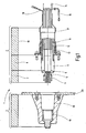
- the Fig. 2 shows a cross section through a device according to the invention 101 for electrical connection in the form of a socket member in a relation to the Fig. 1 enlarged view.
- the insulating member 118 produced by injection molding of a thermoplastic material is substantially bell-shaped with a substantially approximately equal wall thickness of typically 3 to 5 mm.
- the insulating part has an inner cone 121 with an opening width of, for example, 70 mm, and an opening angle ⁇ , which is adapted to the coefficients of friction of the materials in order to avoid self-clamping and, for example, about 3 °.
- the inner cone 121 of the insulating member 118 is flush with the cone 122 of the contact part 119 end formed first control element 123 to the cone 122 is followed at substantially right angles to the longitudinal axis 127 an annular shoulder surface 124 which by means of an insertion bevel 125 for the contact system of the associated Plug element merges into a substantially cylindrical and in particular circular cylindrical contact surface 126 with a clear width of typically about 40 mm.
- the device 101 is designed, for example, for nominal voltages up to 36 kV.
- the contact part 119 at its opposite end to a substantially cylindrical and in particular circular cylindrical connecting pin 128, which is preferably integrally formed and centrally has a threaded bore 129 for attachment, for example, a current continuing busbar.
- the end face of the connecting pin 128 is circularly offset, so that there is an annular contact surface 130 and consequently a geometrically defined contact surface.
- the dimensions are designed for a rated current of 800 amps.
- the diameter of the connecting pin 128 is about 30 mm
- the width of the annular contact surface about 4 mm
- the threaded hole 129 is designed as M12 threaded hole.
- the contact member 119 also integrally forms a circumferential latching ridge 131, to which a jointly formed by the contact member 119 and the insulating member 118 annular chamber or annular groove for a sealant 132 connects.
- the transition from the substantially perpendicular to the longitudinal axis 127 extending second shoulder surface 133 to the substantially cylindrical outer surface 134 of the main portion of the contact portion 119 is formed by an integrally formed axially projecting toward the contact surface 130 second control member 135 in the form of an annular bead.
- the insulating part 118 has, at its end associated with the connecting pin 128, subsequently to a substantially cylindrical or a small wedge angle of less than 1 ° having portion 136 on the inside conically widening annular lip 137.
- This sealing means 132 ensures a gas-tightness of the transition between the insulating part 118 of the overmolded thermoplastic material and the metallic contact part 119, which is made of aluminum, for example.
- the contact part 119 is preferably formed rotationally symmetrical with respect to the longitudinal axis 127.
- the insulating part 118 integrally forms an annular mounting flange 138.
- six cap sleeves 139 are integrally formed on the flange 138 of the insulating member 118.
- each of these cap sleeves 139 is preferably a metallic threaded bushing 142 (see Fig. 5 ), for the purpose of fixing the device 101 to a housing wall, optionally also with mechanical connection to the associated plug element.
- the Fig. 3 shows a cross section through the contact part 119 of Fig. 2 , In the area of the contact surface 130 and the cylindrical outer surface 140, which is substantially, in particular with the exception of the annular detent web 131, the connecting pin 128 is provided with a coating which reduces the contact resistance. This can for example be given by a silver layer with a minimum layer thickness of 3 ⁇ m, as in Fig. 3 indicated by dash-dotted lines.
- the contact part 119 has a surface structure, for example a knurling or a groove formed parallel to the longitudinal axis 127.
- the cylindrical bore 126 is preferably also full surface including the bottom surface 141 and also provided in the region of the cone 122 of the first control element 123 also with a silver layer, for example in a thickness of about 5 microns.
- the Fig. 4 shows an enlarged section from the region of the transition from the insulating member 118 to the contact member 119 in the region of the sealant 132.
- the contact member 119 forms on two sides and the insulating member 118 on one side an annular groove-shaped chamber for the sealant 132, through which a gas-tight connection is ensured.
- pending protective gas for example, sulfur hexafluoride (SF6), do not get into the generally open to the atmosphere region of the cylindrical bore 126.
- the annular bead-shaped second control element 135 effectively controls the optionally filled with air region of the chamber for the sealant 132.
- the conically widening annular lip 137 facilitates insertion of the sealing means 132. If the pending in the region of the connecting pin 128 gas from the environment is under an overpressure, the sealing means 132 is thereby further held in sealing engagement with the contact member 119 and the insulating member 118.
- the Fig. 5 shows a perspective view of the device 101 of the invention Fig. 2 ,
- a plug element can be inserted and the electrical connection can be continued by means of the connecting pin 121.
- a metallic threaded insert 142 is injected in each of the circumferentially arranged with an angular distance of 60 ° cap sleeves 139.
- the flange 138 forms at the end face a continuous and the cap sleeves interconnecting lowering 143. This essentially serves to ensure a planned installation of the cap sockets 139 or the associated threaded inserts 142, for example, on an associated housing wall.
- a substantially hexagonal web 145 of the recess 143 Radially on the outside and separated by a substantially hexagonal web 145 of the recess 143 extends a substantially also hexagonal groove 144 which is externally bounded by a likewise substantially hexagonal lip 146 and serves to receive a separate sealant.
- the lip 146 is axially set back relative to the web 145, in order to ensure a sealing contact with the web 145 and / or inserted into the groove 144 sealant.
Landscapes
- Engineering & Computer Science (AREA)
- Manufacturing & Machinery (AREA)
- Mechanical Engineering (AREA)
- Connector Housings Or Holding Contact Members (AREA)
- Manufacturing Of Electrical Connectors (AREA)
Claims (14)
- Dispositif (101) de connexion électrique à une ligne d'alimentation en énergie pour la moyenne et pour la haute tension, dans lequel le dispositif (101) comporte une partie (118) isolante et une partie (119) de contact conductrice de l'électricité, caractérisé en ce que la partie (118) isolante est en une matière plastique thermoplastique, en ce que la partie (118) isolante est fabriquée par moulage par injection et en ce que, lors du moulage par injection, la partie (119) de contact est introduite dans le moule d'injection et est recouverte de la matière plastique en laissant au moins une ouverture d'accès.
- Dispositif (101) suivant la revendication 1, caractérisé en ce qu'au moins au point de la transition de la pièce (119) de contact à la partie (118) isolante est disposé un moyen (132) d'étanchéité pour la production d'une liaison étanche au gaz entre la partie (118) isolante et la partie (119) de contact.
- Dispositif (101) suivant la revendication 2, caractérisé en ce que le moyen (132) d'étanchéité peut être enfiché après le moulage par injection dans une chambre formée par la partie (118) isolante et par la partie (119) de contact.
- Dispositif (101) suivant l'une des revendications 1 à 3, caractérisé en ce que la partie (119) de contact forme d'une seule pièce des éléments (123, 125) de commande du champ électrique.
- Dispositif (101) suivant l'une des revendications 1 à 4, caractérisé en ce que la partie (119) de contact forme d'une seule pièce un contact linéaire pour prolonger la liaison électrique.
- Dispositif (101) suivant l'une des revendications 1 à 5, caractérisé en ce que la partie (119) de contact a, sur sa surface d'application associée à la partie (118) isolante, au moins par endroit, une structure de surface.
- Dispositif (101) suivant l'une des revendications 1 à 6, caractérisé en ce que la matière plastique de la partie (118) isolante comporte un polyamide, notamment un polyamide partiellement aromatique.
- Dispositif (101) suivant la revendication 7, caractérisé en ce que la matière plastique thermoplastique est renforcée par de la fibre de verre ou par une substance minérale.
- Dispositif (101) suivant l'une des revendications 1 à 8, caractérisé en ce que c'est un dispositif à enfichage et la partie (118) isolante forme un corps de fiche ou un corps de douille.
- Dispositif (101) suivant l'une des revendications 1 à 9, caractérisé en ce que la partie (118) isolante a un cône intérieur ou un cône extérieur.
- Procédé de fabrication d'une partie (118) isolante d'un dispositif (101) de liaison électrique avec une ligne d'alimentation en énergie pour la moyenne tension ou la haute tension, dans lequel on met une partie (119) de contact conductrice de l'électricité dans un moule d'injection et on injecte ensuite de la matière plastique thermoplastique avec formation de la partie (118) isolante autour de la partie (119) de contact en laissant au moins une ouverture d'accès à la partie (119) de contact.
- Procédé suivant la revendication 11, caractérisé en ce que l'on effectue l'opération de moulage par injection au moins en partie sous vide ou dans une atmosphère de gaz inerte.
- Procédé suivant la revendication 11 ou 12, caractérisé en ce qu'on porte la masse de matière plastique avant le moulage par injection à une température de plus de 180°C, notamment de plus de 250°C, et de préférence comprise entre 300 et 350°C, avant d'avoir introduit la masse de matière plastique dans le moule, qui a une température de plus de 60°C, notamment de plus de 90°C, et de préférence comprise entre 100 et 160°C.
- Procédé suivant l'une des revendications 11 à 13, caractérisé en ce qu'on transforme la matière plastique thermoplastique ayant sa couleur propre, notamment sans colorant supplémentaire.
Applications Claiming Priority (2)
| Application Number | Priority Date | Filing Date | Title |
|---|---|---|---|
| DE10332118 | 2003-07-09 | ||
| DE10332118A DE10332118A1 (de) | 2003-07-09 | 2003-07-09 | Vorrichtung zum elektrischen Verbinden mit einer Energieversorgungsleitung für Mittel- oder Hochspannung sowie Verfahren zur Herstellung eines Isolierteils einer solchen Vorrichtung |
Publications (3)
| Publication Number | Publication Date |
|---|---|
| EP1496576A2 EP1496576A2 (fr) | 2005-01-12 |
| EP1496576A3 EP1496576A3 (fr) | 2008-03-26 |
| EP1496576B1 true EP1496576B1 (fr) | 2012-04-04 |
Family
ID=33441765
Family Applications (1)
| Application Number | Title | Priority Date | Filing Date |
|---|---|---|---|
| EP04016065A Revoked EP1496576B1 (fr) | 2003-07-09 | 2004-07-08 | Dispositif de connexion électrique avec une ligne d'alimentation en énergie pour moyenne et haute tension ainsi que procédé de fabrication d'une partie isolante d'un tel dispositif |
Country Status (4)
| Country | Link |
|---|---|
| EP (1) | EP1496576B1 (fr) |
| AT (1) | ATE552630T1 (fr) |
| DE (1) | DE10332118A1 (fr) |
| ES (1) | ES2381106T3 (fr) |
Families Citing this family (4)
| Publication number | Priority date | Publication date | Assignee | Title |
|---|---|---|---|---|
| EP1845596A1 (fr) * | 2006-04-13 | 2007-10-17 | ABB Research Ltd | Dispositif de connexion électrique et procédé de fabrication d'un tel dispositif |
| EP2276041B1 (fr) | 2009-07-15 | 2013-09-25 | ABB Research Ltd. | Dispositif de connexion électrique et installation électrique |
| EP2276040B1 (fr) | 2009-07-15 | 2017-03-01 | ABB Research LTD | Dispositif pour connexion électrique, procédé de production d'un tel dispositif, et installation électrique |
| CN105490076B (zh) * | 2016-01-04 | 2018-03-16 | 北京航天试验技术研究所 | 适用于真空或高压环境下的电容式传感器引线密封插头 |
Family Cites Families (11)
| Publication number | Priority date | Publication date | Assignee | Title |
|---|---|---|---|---|
| DE2944120C2 (de) | 1979-10-30 | 1983-02-10 | Siemens AG, 1000 Berlin und 8000 München | Elastisches Steuerelement für Garnituren elektrischer Kabel sowie Verfahren zur Herstellung eines solchen Steuerelementes |
| DE3247673C2 (de) * | 1982-12-23 | 1986-02-13 | Karl Pfisterer Elektrotechnische Spezialartikel Gmbh & Co Kg, 7000 Stuttgart | Steckerbuchse mit einem Feldsteuerkörper |
| DE3611462A1 (de) * | 1986-04-05 | 1987-10-15 | Pfisterer Elektrotech Karl | Verbindungsgarnitur fuer leiter eines mittelspannungs- oder hochspannungsnetzes |
| DE4001191A1 (de) * | 1990-01-17 | 1991-07-18 | Concordia Sprecher Energie | Steckverbinder |
| JPH0438113A (ja) | 1990-05-31 | 1992-02-07 | Furukawa Electric Co Ltd:The | 電極埋込みエポキシユニットの製造方法 |
| DE4135391C1 (en) * | 1991-10-26 | 1992-12-10 | Karl Pfisterer Elektrotechnische Spezialartikel Gmbh & Co Kg, 7000 Stuttgart, De | Cable connector for medium high voltage and high current - has socket with cup-shaped contact element, and cylindrical insulating housing covering inserted cable |
| DE4224672C1 (fr) * | 1992-07-25 | 1993-09-09 | Karl Pfisterer Elektrotechnische Spezialartikel Gmbh & Co Kg, 7000 Stuttgart, De | |
| DE19717302A1 (de) * | 1997-04-24 | 1998-10-29 | Battenfeld Gmbh | Verfahren und Vorrichtung zur Herstellung von Formteilen aus Kunststoff |
| FR2783082B1 (fr) * | 1998-09-09 | 2000-11-24 | Siemens Automotive Sa | Cable electrique surmoule et procede de realisation d'un tel cable |
| DE10006211C2 (de) * | 2000-02-11 | 2003-11-27 | Robert Virant | Formgebend umspritzte, elektrische und/oder elektronische Komponente und Verfahren zur Herstellung |
| US6830475B2 (en) * | 2002-05-16 | 2004-12-14 | Homac Mfg. Company | Electrical connector with visual seating indicator and associated methods |
-
2003
- 2003-07-09 DE DE10332118A patent/DE10332118A1/de not_active Withdrawn
-
2004
- 2004-07-08 EP EP04016065A patent/EP1496576B1/fr not_active Revoked
- 2004-07-08 AT AT04016065T patent/ATE552630T1/de active
- 2004-07-08 ES ES04016065T patent/ES2381106T3/es not_active Expired - Lifetime
Also Published As
| Publication number | Publication date |
|---|---|
| EP1496576A2 (fr) | 2005-01-12 |
| ATE552630T1 (de) | 2012-04-15 |
| ES2381106T3 (es) | 2012-05-23 |
| DE10332118A1 (de) | 2005-02-10 |
| EP1496576A3 (fr) | 2008-03-26 |
Similar Documents
| Publication | Publication Date | Title |
|---|---|---|
| EP0889774B1 (fr) | Capteur en plastique et son procede de fabrication | |
| DE60314867T2 (de) | Elektrischer verbinder bestehend aus elastomerem werkstoff und zugehörige verfahren | |
| DE3650112T3 (de) | Kabelverbindung. | |
| EP3821260B1 (fr) | Dispositif diviseur de tension à structure en barettes | |
| EP2950399B1 (fr) | Etanchéification de l'emplacement de liaison entre deux conducteurs | |
| EP1496576B1 (fr) | Dispositif de connexion électrique avec une ligne d'alimentation en énergie pour moyenne et haute tension ainsi que procédé de fabrication d'une partie isolante d'un tel dispositif | |
| DE4225267C2 (de) | Abdichtungsvorrichtung für ein elektronisches Schaltgerät | |
| WO1996011408A1 (fr) | Garniture se presentant sous forme de traversee ou de douille pour connecteur de cable | |
| WO2008037710A1 (fr) | Machine électrique, notamment moteur électrique, munie d'un câble de raccordement serti du côté de la machine | |
| DE4423985C2 (de) | Verfahren zur Herstellung einer feuchtigkeitsdichten Verbindung einer elektrischen Leitung mit einem Thermistor eines Temperatursensors | |
| DE202012004919U1 (de) | Dichtungselement für einen elektrischen Steckverbinder und elektrischer Steckverbinder | |
| EP3818602B1 (fr) | Manchon de raccordement | |
| EP3364504A1 (fr) | Connecteur à fiche cylindrique | |
| EP1657795B1 (fr) | Connecteur enfichable de câble d'un dispositif de connexion enfichable pour la technologie de la moyenne et de l'haute tension | |
| DE102009052353A1 (de) | Kontaktstecker | |
| EP3340392A1 (fr) | Système de branchement de conduites électriques | |
| DE19731458C1 (de) | Sensor zum Erfassen der Verunreinigung eines Fluids | |
| EP3358690A1 (fr) | Manchon de raccordement | |
| DE20310876U1 (de) | Vorrichtung zum elektrischen Verbinden mit einer Energieversorgungsleitung für Mittel- oder Hochspannung sowie Einrichtung zur Herstellung eines Isolierteils einer solchen Vorrichtung | |
| EP2448369B1 (fr) | Dispositif de raccordement électrique pour l'élément de chauffage électrique d'une buse à canal chaud | |
| DE3326386C2 (fr) | ||
| DE3806369A1 (de) | Verfahren zur herstellung eines kabelsteckers und giess- oder spritzform zur durchfuehrung des verfahrens | |
| EP3821259B1 (fr) | Dispositif diviseur de tension comprenant un diélectrique à base de siloxane | |
| DE102009055024A1 (de) | Verfahren zum Herstellen eines Leitungssatzes für eine elektrische Maschine, Leitungssatz und elektrische Maschine | |
| DE3538193C2 (fr) |
Legal Events
| Date | Code | Title | Description |
|---|---|---|---|
| PUAI | Public reference made under article 153(3) epc to a published international application that has entered the european phase |
Free format text: ORIGINAL CODE: 0009012 |
|
| AK | Designated contracting states |
Kind code of ref document: A2 Designated state(s): AT BE BG CH CY CZ DE DK EE ES FI FR GB GR HU IE IT LI LU MC NL PL PT RO SE SI SK TR |
|
| AX | Request for extension of the european patent |
Extension state: AL HR LT LV MK |
|
| PUAL | Search report despatched |
Free format text: ORIGINAL CODE: 0009013 |
|
| AK | Designated contracting states |
Kind code of ref document: A3 Designated state(s): AT BE BG CH CY CZ DE DK EE ES FI FR GB GR HU IE IT LI LU MC NL PL PT RO SE SI SK TR |
|
| AX | Request for extension of the european patent |
Extension state: AL HR LT LV MK |
|
| 17P | Request for examination filed |
Effective date: 20080417 |
|
| AKX | Designation fees paid |
Designated state(s): AT BE BG CH CY CZ DE DK EE ES FI FR GB GR HU IE IT LI LU MC NL PL PT RO SE SI SK TR |
|
| RAP1 | Party data changed (applicant data changed or rights of an application transferred) |
Owner name: PFISTERER KONTAKTSYSTEME GMBH |
|
| 17Q | First examination report despatched |
Effective date: 20100325 |
|
| GRAP | Despatch of communication of intention to grant a patent |
Free format text: ORIGINAL CODE: EPIDOSNIGR1 |
|
| RTI1 | Title (correction) |
Free format text: DEVICE FOR ELECTRICAL CONNECTION WITH A POWER SUPPLY LINE FOR MEDIUM OR HIGH VOLTAGE AND PROCESS FOR MANUFACTURING AN INSULATING PORTION OF SUCH A DEVICE |
|
| GRAC | Information related to communication of intention to grant a patent modified |
Free format text: ORIGINAL CODE: EPIDOSCIGR1 |
|
| GRAS | Grant fee paid |
Free format text: ORIGINAL CODE: EPIDOSNIGR3 |
|
| GRAA | (expected) grant |
Free format text: ORIGINAL CODE: 0009210 |
|
| AK | Designated contracting states |
Kind code of ref document: B1 Designated state(s): AT BE BG CH CY CZ DE DK EE ES FI FR GB GR HU IE IT LI LU MC NL PL PT RO SE SI SK TR |
|
| REG | Reference to a national code |
Ref country code: GB Ref legal event code: FG4D Free format text: NOT ENGLISH |
|
| REG | Reference to a national code |
Ref country code: CH Ref legal event code: NV Representative=s name: ISLER & PEDRAZZINI AG Ref country code: CH Ref legal event code: EP |
|
| REG | Reference to a national code |
Ref country code: AT Ref legal event code: REF Ref document number: 552630 Country of ref document: AT Kind code of ref document: T Effective date: 20120415 |
|
| REG | Reference to a national code |
Ref country code: IE Ref legal event code: FG4D Free format text: LANGUAGE OF EP DOCUMENT: GERMAN |
|
| REG | Reference to a national code |
Ref country code: NL Ref legal event code: T3 |
|
| REG | Reference to a national code |
Ref country code: ES Ref legal event code: FG2A Ref document number: 2381106 Country of ref document: ES Kind code of ref document: T3 Effective date: 20120523 |
|
| REG | Reference to a national code |
Ref country code: DE Ref legal event code: R096 Ref document number: 502004013408 Country of ref document: DE Effective date: 20120531 |
|
| PG25 | Lapsed in a contracting state [announced via postgrant information from national office to epo] |
Ref country code: CY Free format text: LAPSE BECAUSE OF FAILURE TO SUBMIT A TRANSLATION OF THE DESCRIPTION OR TO PAY THE FEE WITHIN THE PRESCRIBED TIME-LIMIT Effective date: 20120404 Ref country code: SE Free format text: LAPSE BECAUSE OF FAILURE TO SUBMIT A TRANSLATION OF THE DESCRIPTION OR TO PAY THE FEE WITHIN THE PRESCRIBED TIME-LIMIT Effective date: 20120404 Ref country code: FI Free format text: LAPSE BECAUSE OF FAILURE TO SUBMIT A TRANSLATION OF THE DESCRIPTION OR TO PAY THE FEE WITHIN THE PRESCRIBED TIME-LIMIT Effective date: 20120404 Ref country code: SI Free format text: LAPSE BECAUSE OF FAILURE TO SUBMIT A TRANSLATION OF THE DESCRIPTION OR TO PAY THE FEE WITHIN THE PRESCRIBED TIME-LIMIT Effective date: 20120404 Ref country code: PL Free format text: LAPSE BECAUSE OF FAILURE TO SUBMIT A TRANSLATION OF THE DESCRIPTION OR TO PAY THE FEE WITHIN THE PRESCRIBED TIME-LIMIT Effective date: 20120404 |
|
| PG25 | Lapsed in a contracting state [announced via postgrant information from national office to epo] |
Ref country code: GR Free format text: LAPSE BECAUSE OF FAILURE TO SUBMIT A TRANSLATION OF THE DESCRIPTION OR TO PAY THE FEE WITHIN THE PRESCRIBED TIME-LIMIT Effective date: 20120705 Ref country code: PT Free format text: LAPSE BECAUSE OF FAILURE TO SUBMIT A TRANSLATION OF THE DESCRIPTION OR TO PAY THE FEE WITHIN THE PRESCRIBED TIME-LIMIT Effective date: 20120806 |
|
| PLBI | Opposition filed |
Free format text: ORIGINAL CODE: 0009260 |
|
| BERE | Be: lapsed |
Owner name: PFISTERER KONTAKTSYSTEME G.M.B.H. Effective date: 20120731 |
|
| PG25 | Lapsed in a contracting state [announced via postgrant information from national office to epo] |
Ref country code: SK Free format text: LAPSE BECAUSE OF FAILURE TO SUBMIT A TRANSLATION OF THE DESCRIPTION OR TO PAY THE FEE WITHIN THE PRESCRIBED TIME-LIMIT Effective date: 20120404 Ref country code: CZ Free format text: LAPSE BECAUSE OF FAILURE TO SUBMIT A TRANSLATION OF THE DESCRIPTION OR TO PAY THE FEE WITHIN THE PRESCRIBED TIME-LIMIT Effective date: 20120404 Ref country code: EE Free format text: LAPSE BECAUSE OF FAILURE TO SUBMIT A TRANSLATION OF THE DESCRIPTION OR TO PAY THE FEE WITHIN THE PRESCRIBED TIME-LIMIT Effective date: 20120404 Ref country code: RO Free format text: LAPSE BECAUSE OF FAILURE TO SUBMIT A TRANSLATION OF THE DESCRIPTION OR TO PAY THE FEE WITHIN THE PRESCRIBED TIME-LIMIT Effective date: 20120404 Ref country code: DK Free format text: LAPSE BECAUSE OF FAILURE TO SUBMIT A TRANSLATION OF THE DESCRIPTION OR TO PAY THE FEE WITHIN THE PRESCRIBED TIME-LIMIT Effective date: 20120404 |
|
| 26 | Opposition filed |
Opponent name: ABB AB Effective date: 20121228 |
|
| PLAX | Notice of opposition and request to file observation + time limit sent |
Free format text: ORIGINAL CODE: EPIDOSNOBS2 |
|
| PG25 | Lapsed in a contracting state [announced via postgrant information from national office to epo] |
Ref country code: MC Free format text: LAPSE BECAUSE OF NON-PAYMENT OF DUE FEES Effective date: 20120731 |
|
| GBPC | Gb: european patent ceased through non-payment of renewal fee |
Effective date: 20120708 |
|
| REG | Reference to a national code |
Ref country code: DE Ref legal event code: R026 Ref document number: 502004013408 Country of ref document: DE Effective date: 20121228 |
|
| PLAB | Opposition data, opponent's data or that of the opponent's representative modified |
Free format text: ORIGINAL CODE: 0009299OPPO |
|
| PG25 | Lapsed in a contracting state [announced via postgrant information from national office to epo] |
Ref country code: GB Free format text: LAPSE BECAUSE OF NON-PAYMENT OF DUE FEES Effective date: 20120708 |
|
| REG | Reference to a national code |
Ref country code: IE Ref legal event code: MM4A |
|
| R26 | Opposition filed (corrected) |
Opponent name: ABB AB Effective date: 20121228 |
|
| PLAF | Information modified related to communication of a notice of opposition and request to file observations + time limit |
Free format text: ORIGINAL CODE: EPIDOSCOBS2 |
|
| PG25 | Lapsed in a contracting state [announced via postgrant information from national office to epo] |
Ref country code: BE Free format text: LAPSE BECAUSE OF NON-PAYMENT OF DUE FEES Effective date: 20120731 |
|
| PLBB | Reply of patent proprietor to notice(s) of opposition received |
Free format text: ORIGINAL CODE: EPIDOSNOBS3 |
|
| PG25 | Lapsed in a contracting state [announced via postgrant information from national office to epo] |
Ref country code: IE Free format text: LAPSE BECAUSE OF NON-PAYMENT OF DUE FEES Effective date: 20120708 Ref country code: BG Free format text: LAPSE BECAUSE OF FAILURE TO SUBMIT A TRANSLATION OF THE DESCRIPTION OR TO PAY THE FEE WITHIN THE PRESCRIBED TIME-LIMIT Effective date: 20120704 |
|
| PGFP | Annual fee paid to national office [announced via postgrant information from national office to epo] |
Ref country code: FR Payment date: 20130628 Year of fee payment: 10 |
|
| PGFP | Annual fee paid to national office [announced via postgrant information from national office to epo] |
Ref country code: ES Payment date: 20130702 Year of fee payment: 10 Ref country code: AT Payment date: 20130722 Year of fee payment: 10 Ref country code: DE Payment date: 20130521 Year of fee payment: 10 Ref country code: NL Payment date: 20130724 Year of fee payment: 10 Ref country code: CH Payment date: 20130711 Year of fee payment: 10 |
|
| PGFP | Annual fee paid to national office [announced via postgrant information from national office to epo] |
Ref country code: IT Payment date: 20130704 Year of fee payment: 10 |
|
| PG25 | Lapsed in a contracting state [announced via postgrant information from national office to epo] |
Ref country code: TR Free format text: LAPSE BECAUSE OF FAILURE TO SUBMIT A TRANSLATION OF THE DESCRIPTION OR TO PAY THE FEE WITHIN THE PRESCRIBED TIME-LIMIT Effective date: 20120404 |
|
| PG25 | Lapsed in a contracting state [announced via postgrant information from national office to epo] |
Ref country code: LU Free format text: LAPSE BECAUSE OF NON-PAYMENT OF DUE FEES Effective date: 20120708 |
|
| PG25 | Lapsed in a contracting state [announced via postgrant information from national office to epo] |
Ref country code: HU Free format text: LAPSE BECAUSE OF FAILURE TO SUBMIT A TRANSLATION OF THE DESCRIPTION OR TO PAY THE FEE WITHIN THE PRESCRIBED TIME-LIMIT Effective date: 20040708 |
|
| REG | Reference to a national code |
Ref country code: DE Ref legal event code: R119 Ref document number: 502004013408 Country of ref document: DE |
|
| REG | Reference to a national code |
Ref country code: NL Ref legal event code: V1 Effective date: 20150201 |
|
| REG | Reference to a national code |
Ref country code: CH Ref legal event code: PL |
|
| REG | Reference to a national code |
Ref country code: AT Ref legal event code: MM01 Ref document number: 552630 Country of ref document: AT Kind code of ref document: T Effective date: 20140708 |
|
| PG25 | Lapsed in a contracting state [announced via postgrant information from national office to epo] |
Ref country code: NL Free format text: LAPSE BECAUSE OF NON-PAYMENT OF DUE FEES Effective date: 20150201 |
|
| REG | Reference to a national code |
Ref country code: FR Ref legal event code: ST Effective date: 20150331 |
|
| PG25 | Lapsed in a contracting state [announced via postgrant information from national office to epo] |
Ref country code: CH Free format text: LAPSE BECAUSE OF NON-PAYMENT OF DUE FEES Effective date: 20140731 Ref country code: LI Free format text: LAPSE BECAUSE OF NON-PAYMENT OF DUE FEES Effective date: 20140731 Ref country code: IT Free format text: LAPSE BECAUSE OF NON-PAYMENT OF DUE FEES Effective date: 20140708 Ref country code: DE Free format text: LAPSE BECAUSE OF NON-PAYMENT OF DUE FEES Effective date: 20150203 |
|
| REG | Reference to a national code |
Ref country code: DE Ref legal event code: R119 Ref document number: 502004013408 Country of ref document: DE Effective date: 20150203 |
|
| PG25 | Lapsed in a contracting state [announced via postgrant information from national office to epo] |
Ref country code: FR Free format text: LAPSE BECAUSE OF NON-PAYMENT OF DUE FEES Effective date: 20140731 Ref country code: AT Free format text: LAPSE BECAUSE OF NON-PAYMENT OF DUE FEES Effective date: 20140708 |
|
| REG | Reference to a national code |
Ref country code: ES Ref legal event code: FD2A Effective date: 20160104 |
|
| PG25 | Lapsed in a contracting state [announced via postgrant information from national office to epo] |
Ref country code: ES Free format text: LAPSE BECAUSE OF NON-PAYMENT OF DUE FEES Effective date: 20140709 |
|
| RDAF | Communication despatched that patent is revoked |
Free format text: ORIGINAL CODE: EPIDOSNREV1 |
|
| STAA | Information on the status of an ep patent application or granted ep patent |
Free format text: STATUS: THE PATENT HAS BEEN GRANTED |
|
| REG | Reference to a national code |
Ref country code: DE Ref legal event code: R064 Ref document number: 502004013408 Country of ref document: DE Ref country code: DE Ref legal event code: R103 Ref document number: 502004013408 Country of ref document: DE |
|
| RDAG | Patent revoked |
Free format text: ORIGINAL CODE: 0009271 |
|
| 27W | Patent revoked |
Effective date: 20161202 |
|
| REG | Reference to a national code |
Ref country code: AT Ref legal event code: MA03 Ref document number: 552630 Country of ref document: AT Kind code of ref document: T Effective date: 20161202 |
|
| STAA | Information on the status of an ep patent application or granted ep patent |
Free format text: STATUS: PATENT REVOKED |