EP1497155B1 - Systeme de vision nocture - Google Patents
Systeme de vision nocture Download PDFInfo
- Publication number
- EP1497155B1 EP1497155B1 EP02807306A EP02807306A EP1497155B1 EP 1497155 B1 EP1497155 B1 EP 1497155B1 EP 02807306 A EP02807306 A EP 02807306A EP 02807306 A EP02807306 A EP 02807306A EP 1497155 B1 EP1497155 B1 EP 1497155B1
- Authority
- EP
- European Patent Office
- Prior art keywords
- camera
- window
- vehicle according
- vehicle
- lens
- Prior art date
- Legal status (The legal status is an assumption and is not a legal conclusion. Google has not performed a legal analysis and makes no representation as to the accuracy of the status listed.)
- Expired - Lifetime
Links
Images


Classifications
-
- B—PERFORMING OPERATIONS; TRANSPORTING
- B60—VEHICLES IN GENERAL
- B60R—VEHICLES, VEHICLE FITTINGS, OR VEHICLE PARTS, NOT OTHERWISE PROVIDED FOR
- B60R11/00—Arrangements for holding or mounting articles, not otherwise provided for
- B60R11/04—Mounting of cameras operative during drive; Arrangement of controls thereof relative to the vehicle
-
- B—PERFORMING OPERATIONS; TRANSPORTING
- B60—VEHICLES IN GENERAL
- B60R—VEHICLES, VEHICLE FITTINGS, OR VEHICLE PARTS, NOT OTHERWISE PROVIDED FOR
- B60R1/00—Optical viewing arrangements; Real-time viewing arrangements for drivers or passengers using optical image capturing systems, e.g. cameras or video systems specially adapted for use in or on vehicles
- B60R1/20—Real-time viewing arrangements for drivers or passengers using optical image capturing systems, e.g. cameras or video systems specially adapted for use in or on vehicles
- B60R1/22—Real-time viewing arrangements for drivers or passengers using optical image capturing systems, e.g. cameras or video systems specially adapted for use in or on vehicles for viewing an area outside the vehicle, e.g. the exterior of the vehicle
- B60R1/23—Real-time viewing arrangements for drivers or passengers using optical image capturing systems, e.g. cameras or video systems specially adapted for use in or on vehicles for viewing an area outside the vehicle, e.g. the exterior of the vehicle with a predetermined field of view
- B60R1/24—Real-time viewing arrangements for drivers or passengers using optical image capturing systems, e.g. cameras or video systems specially adapted for use in or on vehicles for viewing an area outside the vehicle, e.g. the exterior of the vehicle with a predetermined field of view in front of the vehicle
-
- B—PERFORMING OPERATIONS; TRANSPORTING
- B60—VEHICLES IN GENERAL
- B60R—VEHICLES, VEHICLE FITTINGS, OR VEHICLE PARTS, NOT OTHERWISE PROVIDED FOR
- B60R1/00—Optical viewing arrangements; Real-time viewing arrangements for drivers or passengers using optical image capturing systems, e.g. cameras or video systems specially adapted for use in or on vehicles
- B60R1/20—Real-time viewing arrangements for drivers or passengers using optical image capturing systems, e.g. cameras or video systems specially adapted for use in or on vehicles
- B60R1/30—Real-time viewing arrangements for drivers or passengers using optical image capturing systems, e.g. cameras or video systems specially adapted for use in or on vehicles providing vision in the non-visible spectrum, e.g. night or infrared vision
-
- G—PHYSICS
- G02—OPTICS
- G02B—OPTICAL ELEMENTS, SYSTEMS OR APPARATUS
- G02B23/00—Telescopes, e.g. binoculars; Periscopes; Instruments for viewing the inside of hollow bodies; Viewfinders; Optical aiming or sighting devices
- G02B23/12—Telescopes, e.g. binoculars; Periscopes; Instruments for viewing the inside of hollow bodies; Viewfinders; Optical aiming or sighting devices with means for image conversion or intensification
-
- G—PHYSICS
- G02—OPTICS
- G02B—OPTICAL ELEMENTS, SYSTEMS OR APPARATUS
- G02B27/00—Optical systems or apparatus not provided for by any of the groups G02B1/00 - G02B26/00, G02B30/00
- G02B27/01—Head-up displays
-
- H—ELECTRICITY
- H04—ELECTRIC COMMUNICATION TECHNIQUE
- H04N—PICTORIAL COMMUNICATION, e.g. TELEVISION
- H04N23/00—Cameras or camera modules comprising electronic image sensors; Control thereof
- H04N23/20—Cameras or camera modules comprising electronic image sensors; Control thereof for generating image signals from infrared radiation only
-
- B—PERFORMING OPERATIONS; TRANSPORTING
- B60—VEHICLES IN GENERAL
- B60R—VEHICLES, VEHICLE FITTINGS, OR VEHICLE PARTS, NOT OTHERWISE PROVIDED FOR
- B60R2300/00—Details of viewing arrangements using cameras and displays, specially adapted for use in a vehicle
- B60R2300/10—Details of viewing arrangements using cameras and displays, specially adapted for use in a vehicle characterised by the type of camera system used
- B60R2300/106—Details of viewing arrangements using cameras and displays, specially adapted for use in a vehicle characterised by the type of camera system used using night vision cameras
-
- B—PERFORMING OPERATIONS; TRANSPORTING
- B60—VEHICLES IN GENERAL
- B60R—VEHICLES, VEHICLE FITTINGS, OR VEHICLE PARTS, NOT OTHERWISE PROVIDED FOR
- B60R2300/00—Details of viewing arrangements using cameras and displays, specially adapted for use in a vehicle
- B60R2300/20—Details of viewing arrangements using cameras and displays, specially adapted for use in a vehicle characterised by the type of display used
- B60R2300/205—Details of viewing arrangements using cameras and displays, specially adapted for use in a vehicle characterised by the type of display used using a head-up display
-
- B—PERFORMING OPERATIONS; TRANSPORTING
- B60—VEHICLES IN GENERAL
- B60R—VEHICLES, VEHICLE FITTINGS, OR VEHICLE PARTS, NOT OTHERWISE PROVIDED FOR
- B60R2300/00—Details of viewing arrangements using cameras and displays, specially adapted for use in a vehicle
- B60R2300/80—Details of viewing arrangements using cameras and displays, specially adapted for use in a vehicle characterised by the intended use of the viewing arrangement
- B60R2300/8053—Details of viewing arrangements using cameras and displays, specially adapted for use in a vehicle characterised by the intended use of the viewing arrangement for bad weather conditions or night vision
-
- G—PHYSICS
- G02—OPTICS
- G02B—OPTICAL ELEMENTS, SYSTEMS OR APPARATUS
- G02B27/00—Optical systems or apparatus not provided for by any of the groups G02B1/00 - G02B26/00, G02B30/00
- G02B27/01—Head-up displays
- G02B27/0101—Head-up displays characterised by optical features
- G02B2027/0138—Head-up displays characterised by optical features comprising image capture systems, e.g. camera
-
- G—PHYSICS
- G02—OPTICS
- G02B—OPTICAL ELEMENTS, SYSTEMS OR APPARATUS
- G02B27/00—Optical systems or apparatus not provided for by any of the groups G02B1/00 - G02B26/00, G02B30/00
- G02B27/01—Head-up displays
- G02B27/0149—Head-up displays characterised by mechanical features
- G02B2027/0154—Head-up displays characterised by mechanical features with movable elements
- G02B2027/0156—Head-up displays characterised by mechanical features with movable elements with optionally usable elements
Definitions
- THE PRESENT INVENTION relates to a night vision arrangement in the form of a device for the enhancement of night vision of a vehicle, such as an automobile.
- US-A-5,414,439 discloses an arrangement in which a vehicle is equipped with an infra-red sensitive camera which is directed to capture an image of the roadway in front of the vehicle.
- the camera provides an output in the form of a video signal which is processed by a video processor, and which is then passed to a head-up display.
- head-up display units in vehicles such as combat aircraft to enable the pilots of the aircraft to view, simultaneously, the scene on the exterior of the aircraft, and also an image projected on to the head-up display.
- US-A-5,414,439 utilises a head-up display of this general type to enable the driver of the vehicle to view the road in front of the vehicle and, simultaneously, to see an image derived from the infra-red camera.
- the windshield is provided with a semi-transparent mirror which is utilised as a combiner to combine the real image of the road in front of the vehicle as viewed by the driver, and a virtual image of the road ahead.
- the infra-red sensitive camera of US-A-5,414,439 is of conventional design incorporating a lens arrangement which serves to focus an image on a relatively large sensor element which is located in alignment with the optical axis of the lens arrangement.
- the entire camera is rather bulky and the positioning of the camera is shown, schematically, with the camera being mounted within the engine compartment of the vehicle.
- the present invention seeks to provide an improved night vision arrangement.
- a vehicle comprising a night vision arrangement
- the night vision arrangement incorporates a camera, the camera comprising a non-distorting window which is substantially transparent to infra-red light and a separate lens, and an infra-red sensor to capture an image received through the window, therebeing a display unit to display the captured image to a driver of the vehicle.
- a beam deflector is provided in alignment with the window to deflect a beam received through the window and to direct the deflected beam through said lens on to the said sensing means.
- a part of the camera containing the sensor is mounted within the envelope of the vehicle, with the window being positioned or positionable on the exterior of the vehicle. If the main part of the camera, which contains the sensor, is mounted within the envelope of the vehicle, the aerodynamic property of the vehicle will not be influenced substantially by the camera arrangement. Also, the mounting of the camera in position, during the assembly of the vehicle, may be facilitated.
- the beam deflector is adapted to deflect the beam through approximately 90°.
- the angle of deflection of the beam deflected by the beam deflector does depend upon the detailed design of the camera, and the intended location of the camera.
- the camera is mounted in a position with only the window exposed.
- the beam deflector comprises a mirror.
- the beam deflector may comprise a prism or some other optical unit which deflects the beam.
- the deflector and lens are located within a sealed housing, the housing being provided with said window.
- the lens is provided with a hard coated exterior surface which is coated with micro diamond. This may ensure that the lens proves to be durable, especially if the arrangement is used in a harsh environment where there is grit or dust in the air.
- the means for rinsing the window with water may comprise a windscreen washer arrangement. The rinsing of the window with water may assist in keeping the window clean.
- the means to wipe the window may comprise a wiper blade, a mechanism being provided to effect a relative movement between the window and the wiper blade.
- Advantageously means are provided to protect the window from the environment.
- the window may be protected from the environment at times when the night vision arrangement is not in use.
- the means provided to protect the window from the environment comprise a cover movable to a position in which the window is covered.
- the means to protect the window comprise means to move the camera and the window so that the window is in a retracted and protected position.
- the camera is mounted between the rear of the hood of a motor vehicle and the windshield.
- the camera is mounted in position for pivotal movement about a horizontal axis parallel with the axis of the vehicle between an operative position and a retracted position, a wiper being provided to wipe the window as the camera moves.
- the camera is incorporated into a mirror housing.
- the camera is mounted in a fender or bumper.
- the camera is mounted to be moved vertically between an operative position and a retracted position.
- the camera is provided with a cover movable between a retracted position in which the window is exposed, and a closed position in which the window is covered.
- the camera is adapted to be mounted on the roof of a vehicle.
- the cover is incorporated in a roof mounted aerial.
- the camera is incorporated in a roof rail.
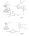
- a night vision arrangement for a vehicle such as motor car comprises a camera arrangement 1 to capture an image, a signal processing unit 2 and a display arrangement 3 adapted to display an image.
- the camera arrangement 1 comprises a window 4 which is transparent to infra-red light through which a beam of infra-red light, forming an image, is to pass into the interior of the camera.
- the window is such that it does not distort the beam of infra-red light, and does not refract or diffract the beam. Thus the window does not focus the beam.
- the window 4 is provided with a flat front face, that flat front face being provided with a hard coating 5 formed preferably of micro-size diamond.
- the window 4 is perpendicular to an optical axis, and, when the camera unit 1 is positioned on a motor vehicle, the optical axis in front of the window is directed towards the roadway in front of the vehicle, so that the camera can capture an image of the roadway in front of the vehicle.
- a beam deflector 6 which, in the illustrated embodiment of the invention, is constituted by a mirror 7 which is inclined at substantially 45° to the optical axis.
- the beam deflector 6 serves to deflect the beam passing through the window 4 by approximately 90°.
- the beam deflector 6 is connected, by means of an elongate hollow neck 8, to a main part of the housing 9 of the camera 1. Contained within the elongate neck 8 is a focusing lens 10, which serves to focus light from the beam deflector 6 on to a sensor 11 present within the main part of the housing 9.
- the sensor 11 is an infra-red sensor, and may comprise a microbolometer.
- the sensor may be a charge-coupled device.
- the sensor is shown mounted on an electronic unit 12 which receives the signals from the sensor and which provides an output on the output lead 13.
- the infra-red sensitive camera 1 is provided with a housing 9 which contains an infra-red sensor 11 which is adapted to capture an image, and the housing has a hollow neck 8 extending to a beam deflector 6 which is located adjacent the window 4.
- the housing is sealed to prevent the ingress of dirt or moisture.
- the window may be formed by one face of a prism that acts as the beam deflector.
- the output 13 from the camera 1 passes through an image processor unit 2 which provides a signal on a lead 14 which passes to an image generator 15.
- the image generator 15 may be a cathode ray tube device, or some other equivalent arrangement.
- the image generator 15 is positioned at an appropriate location generally in front of a combiner 16, which may be mounted on the windshield of a motor vehicle, and which may be a semi-transparent aspheric mirror.
- the camera 1 will be mounted in a motor vehicle so that the optical axis which is perpendicular to the window 4 is directed generally along the roadway in front of the motor vehicle, enabling the camera 1 to generate an infra-red image of the roadway in front of the vehicle. That image is presented on the image generator 15.
- the driver of the vehicle may thus simultaneously view, in the combiner 16, the real image of the roadway outside the vehicle, and a virtual image of the roadway, as presented on the image generator 15.
- FIG. 2 illustrates a second embodiment of the invention in which the camera 1 and signal processor 2 are exactly as described above with reference to Figure 1. These components will not be re-described.
- the output 14 of the signal processing unit 2 is connected directly to a monitor 17, which may be in the form of a cathode ray tube or the like.
- the monitor 17 is located at a position where it can be viewed by the driver of a motor vehicle.
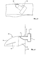
- a camera 1 as described above, is illustrated mounted in position on a motor vehicle.
- the internal components of the camera are not shown in these figures.
- the camera 1 is mounted in position with the main housing 9 being located within a recess 20 that is formed between the lower edge of the windscreen 21, and the upper edge of the hood or bonnet 22.
- the recess 20 may also contain part of the windscreen wiper mechanism.
- the camera 1 is located in position so that the main housing 9 is located within the recess, with the neck 8 extending vertically upwardly, so that the window 4 is located above the upper edge of the bonnet 22, thus ensuring that the window 4 has an adequate "view" of the road in front of the vehicle.
- the main housing 9 is thus located within the main envelope defined by the vehicle, with only that part of the neck 8 carrying the window 4 projecting beyond the envelope.
- the windscreen washer nozzle 23 is mounted on the bonnet 22 so that when the windscreen washer is actuated, water from the nozzle 23 will impinge upon the window 4, thus facilitating in cleaning the window 4.
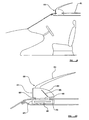
- the camera 1 of the embodiment shown in Figures 3 to 5 is mounted in position for pivotal movement about a substantially horizontal pivot axis 24, the pivot axis being aligned with the axis of the vehicle.
- the entire camera may thus pivot from a first operative position, as shown in Figures 3 and 4, in which the window 4 is located above the rear edge of the bonnet 22, to a retracted position, as shown in Figure 5, in which the lens is positioned beneath the rear edge of the hood or bonnet 2.
- the lens, in this retracted position is somewhat protected from the environment which may contain rain or dust.
- a wiper blade 25 is mounted in position adjacent the rear edge of the hood or bonnet 22 which is located so that, as the camera 1 moves from the operative position of Figure 4 to the retracted position of Figure 5, the wiper 25 wipes the window 4.
- the window 4 is kept in a clean condition by the action of the wiper 25.
- the main housing 9 of the camera is, at all times, within the envelope of the vehicle, with the window 4 being movable to the operative position where it extends beyond the envelope of the vehicle.
- the optical axis of the window 4, when the camera is in the operative position, is very close to the actual line of sight of the driver of the vehicle, if the camera is positioned immediately in front of the driver. This serves to minimise any parallax error which might otherwise arise.
- the camera of the embodiment of Figures 3 to 5 may be driven about the pivot axis 24 by means of an appropriate electric or hydraulic motor.
- the motor may be controlled so that the camera is only moved to the operative position when the night vision arrangement is actuated, although the driver may have a control which can be actuated to cause the camera to move from the operative position to the retracted position, and back again, so that the driver may effect a cleaning of the lens of the camera.
- FIG. 6 illustrates another embodiment of the invention in which a camera 1 as described above is mounted in a motor vehicle, with the camera being mounted in position to form part of a wing mirror unit 30. Again, the internal components of the camera are not shown.
- the wing mirror unit 30 has a base portion 31 connected to part 32 of the door of a vehicle, and has an extension portion 33 which contains the actual mirror 34.
- the camera 1 is mounted in position with the main housing 9 being located within the door, and with the neck 8 extending horizontally into the base portion 31 of the wing mirror unit 30.
- the window 4 is positioned in an appropriate aperture formed in the forward facing part of the base portion 31 of the wing mirror unit 30. The camera may easily be mounted in this position as the motor vehicle is fabricated.
- a camera 1 of the type described above is shown mounted in position within the bumper or fender 40 of the motor vehicle. Again, the internal components of the camera are not shown.
- the camera 1 is shown in position beneath a headlight 41.
- the camera is mounted in position within a recess 42 formed in the bumper or fender with the housing 9 within the envelope of the vehicle.
- the camera is located in position with the neck 8 extending vertically upwardly so that the window 4 is positioned immediately above the top surface of the bumper or fender 40.
- the camera is positioned immediately in front of the driver in order to minimise any parallax problems.
- the camera may move vertically from an upper or elevated position, as shown in solid line, to a lower or retracted position as shown in dotted lines 43.
- the window 4 is retracted into the recess 42 formed in the bumper or fender 40, thus protecting the window 4 from the environment.
- FIG. 8 illustrates a further embodiment in which a camera 1 of the type described above is mounted in position within a bumper or fender 50, and in this figure the internal components of the camera are not shown.
- the camera 1 is located adjacent a headlight 51.
- the bumper or fender 50 defines a recess 52, and the camera 1 is mounted at a fixed position within the recess 52, with the housing 9 within the envelope of the vehicle.
- the neck 8 of the camera extends upwardly so that the window 4 is positioned above the upper edge of the bumper or fender.
- Mounted within the bumper or fender is a pivotally movable cover 53.
- the cover 53 is adapted to pivot about a pivot axis 54.
- the cover may move from a retracted position, as shown in solid lines in Figure 8, in which the window 4 is exposed has a clear view across the top part of the bumper or fender 50, to a closed position, as shown in dotted lines 54 in Figure 8, in which the cover 53 extends in front of and above the window to cover and protect the window 4.
- the aerial unit 60 incorporates an aerial or antenna 62 mounted on an upper housing 63.
- the front part of the upper housing 63 is provided with a window 64, similar to the window 4 of the camera described above, the window 64 being perpendicular to an optical axis aligned with a beam deflector 65 contained within the upper housing 63.
- the upper housing 63 is connected by means of a neck 66 which extends from the lower part of the upper housing 63, to a lower housing 67. Contained within the lower housing 67 is an image detector 68, corresponding to the image detector 11 described above.
- a focusing lens 69 is positioned between the beam deflector 65 and the image deflector 68.
- the beam deflector 65 deflects the beam entering the camera through the window 4 by approximately 90° so that the deflected beam passed through the lens 69 and is focused on to the image detector 68.
- the upper housing 63 and the lower housing 67 together constitute a camera which is, effectively, of the same operative design as the camera 1 described above.
- the camera of the embodiments of Figures 9 and 10 is mounted in position with the neck 66 passing through an aperture 70 formed in the roof sheet of the vehicle.
- the lower housing 67, containing the sensor 68 is mounted within the envelope of the vehicle.
- the lower housing 67 is larger than the aperture 70, and so the aerial unit 60 cannot easily be removed from the vehicle.
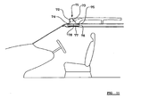
- FIG 11 illustrates a further embodiment of the invention in which a camera is incorporated within a roof rail of the motor vehicle.
- a roof rail 70 of a motor vehicle has, at its forward-most end, a chamber 71, the front part of the chamber being provided with a window 72.
- the window 72 corresponds with the window 4 as described above.
- Contained within the chamber 71 in alignment with the optical axis of the lens 4 is a beam deflector constituted, in this embodiment, by an inclined mirror 73.
- the lower part of the chamber 71 is connected, by means of a relatively narrow neck 74 which passes through an aperture 75 formed in the roof of the vehicle, the neck 74 terminating in an enlarged lower housing 76 which contains an infra-red sensor 77 of the type described above.
- the beam entering the camera through the lens 72 is focussed onto the infra-red sensor by a lens 78 located between the mirror 73 and the sensor 77. It is to be appreciated that in this embodiment the housing containing the sensor is within the envelope of the vehicle.
- a heater may be provided to heat the window of the camera to minimise or obviate condensation on the window.
- the heater may be an electric heater or may be means to direct heated air from the vehicle heating system on to the window.
Landscapes
- Engineering & Computer Science (AREA)
- Physics & Mathematics (AREA)
- Multimedia (AREA)
- Mechanical Engineering (AREA)
- General Physics & Mathematics (AREA)
- Optics & Photonics (AREA)
- Astronomy & Astrophysics (AREA)
- Signal Processing (AREA)
- Fittings On The Vehicle Exterior For Carrying Loads, And Devices For Holding Or Mounting Articles (AREA)
- Closed-Circuit Television Systems (AREA)
- Rear-View Mirror Devices That Are Mounted On The Exterior Of The Vehicle (AREA)
- Studio Devices (AREA)
- Instrument Panels (AREA)
Claims (16)
- Un véhicule comprenant un dispositif de vision nocturne, le dispositif de vision nocturne incorporant une caméra (1), la caméra (1) comprenant une fenêtre (4) non distordante, sensiblement transparente à la lumière infrarouge, et une lentille (10) séparée, et un capteur à infrarouge (11), pour capturer une image reçue à travers la fenêtre (4), de manière qu'une unité d'affichage (15) affiche l'image capturée à un conducteur du véhicule, caractérisé en ce que, dans la caméra (1), est prévu un déflecteur de faisceau (6) en alignement avec la fenêtre (4), pour dévier un faisceau reçu à travers la fenêtre (4) et pour diriger le faisceau dévié à travers ladite lentille (10) sur ledit capteur à infrarouge (11), la partie de la caméra contenant le capteur étant montée à l'intérieur de l'enveloppe principale du véhicule, et la fenêtre (4), lorsqu'elle est en condition de fonctionnement, étant située au-delà de ladite enveloppe.
- Un véhicule selon la revendication 1, dans lequel le déflecteur de faisceau (6) est adapté pour dévier le faisceau d'environ 90°.
- Un véhicule selon la revendication 1 ou la revendication 2, dans lequel le déflecteur de faisceau (6) comprend un miroir (7).
- Un véhicule selon l'une quelconque des revendications précédentes, dans lequel le déflecteur (6) et la lentille (10) sont situés dans un boîtier (9) étanche, le boîtier étant muni de ladite fenêtre (4).
- Un véhicule selon l'une quelconque des revendications précédentes, dans lequel des moyens sont prévus pour chauffer la fenêtre (4) de la caméra (1).
- Un véhicule selon l'une quelconque des revendications précédentes, dans lequel des moyens sont prévus pour protéger la fenêtre (4) de l'environnement.
- Un véhicule selon la revendication 6, dans lequel les moyens fournis pour protéger la fenêtre (4) de l'environnement comprennent un couvercle (53), déplaçable à une position à laquelle la fenêtre (4) est couverte.
- Un véhicule selon la revendication 6, dans lequel les moyens pour protéger la fenêtre (4) comprennent des moyens pour déplacer la caméra (1) et la lentille (10), de manière que la lentille (40) soit à une position rétractée et protégée.
- Un véhicule selon la revendication 8, dans lequel la caméra (1) est montée en position pour un mouvement de pivotement autour d'un axe (24) horizontal, parallèle à l'axe du véhicule, entre une position fonctionnelle et une position rétractée.
- Un véhicule selon l'une quelconque des revendications 1 à 8, dans lequel la caméra (1) est incorporée dans un boîtier à miroir (30).
- Un véhicule selon l'une quelconque des revendications 1 à 8, dans lequel la caméra (1) est montée dans une aile ou un pare-chocs (50).
- Un véhicule selon la revendication 11, dans lequel la caméra (1) est montée pour être déplacée verticalement entre une position fonctionnelle et une position rétractée.
- Un véhicule selon la revendication 11, dans lequel la caméra est munie d'un couvercle (53), déplaçable entre une position rétractée, à laquelle la fenêtre (4) est exposée, et une position fermée, à laquelle la fenêtre (4) est couverte.
- Un véhicule selon l'une quelconque des revendications 1 à 8, dans lequel la caméra (1) est adaptée pour être montée sur le toit (61) d'un véhicule.
- Un véhicule selon la revendication 14, dans lequel la caméra (1) est incorporée dans une antenne aérienne (62), montée sur le toit.
- Un véhicule selon la revendication 15, dans lequel la caméra (1) est incorporée dans un rail de toit (70).
Priority Applications (1)
| Application Number | Priority Date | Filing Date | Title |
|---|---|---|---|
| AT02807306T ATE336401T1 (de) | 2002-04-23 | 2002-04-23 | Nachtsichtanordnung |
Applications Claiming Priority (1)
| Application Number | Priority Date | Filing Date | Title |
|---|---|---|---|
| PCT/SE2002/000785 WO2003091069A1 (fr) | 2002-04-23 | 2002-04-23 | Systeme de vision nocture |
Publications (2)
| Publication Number | Publication Date |
|---|---|
| EP1497155A1 EP1497155A1 (fr) | 2005-01-19 |
| EP1497155B1 true EP1497155B1 (fr) | 2006-08-16 |
Family
ID=29268143
Family Applications (1)
| Application Number | Title | Priority Date | Filing Date |
|---|---|---|---|
| EP02807306A Expired - Lifetime EP1497155B1 (fr) | 2002-04-23 | 2002-04-23 | Systeme de vision nocture |
Country Status (5)
| Country | Link |
|---|---|
| US (1) | US7592592B2 (fr) |
| EP (1) | EP1497155B1 (fr) |
| JP (1) | JP2005523200A (fr) |
| DE (1) | DE60214047T2 (fr) |
| WO (1) | WO2003091069A1 (fr) |
Families Citing this family (29)
| Publication number | Priority date | Publication date | Assignee | Title |
|---|---|---|---|---|
| US20030202097A1 (en) * | 2000-10-26 | 2003-10-30 | Autoliv Development Ab | Night vision arrangement |
| US7995095B2 (en) | 2001-10-18 | 2011-08-09 | Autoliv Development Ab | Night vision device for a vehicle |
| WO2004047421A2 (fr) | 2002-11-14 | 2004-06-03 | Donnelly Corporation | Systeme d'imagerie pour vehicule |
| DE10342971A1 (de) * | 2003-09-17 | 2005-05-04 | Daimler Chrysler Ag | Vorrichtung zur Außenüberwachung eines Kraftfahrzeugs |
| DE102005028360A1 (de) * | 2005-06-18 | 2006-12-21 | Adc Automotive Distance Control Systems Gmbh | Kraftfahrzeug mit optischen Mittel |
| DE102005030838A1 (de) * | 2005-07-01 | 2007-01-04 | Siemens Ag | Nightvisionsystem |
| US8228177B1 (en) * | 2006-03-31 | 2012-07-24 | Stanley Toshio Yamada | Automobile security device |
| DE102007052617A1 (de) * | 2007-11-05 | 2009-05-07 | GM Global Technology Operations, Inc., Detroit | Kraftfahrzeug mit einer Kamera |
| DE102008012033A1 (de) * | 2008-02-29 | 2009-09-03 | GM Global Technology Operations, Inc., Detroit | Kraftfahrzeug mit einer Kamera |
| DE102008048322B4 (de) * | 2008-09-22 | 2021-08-19 | Volkswagen Ag | Verfahren und Vorrichtung zum Anzeigen einer optischen Umgebungsinformation eines Fahrzeugs in dem Fahrzeug |
| US8704891B2 (en) | 2009-12-23 | 2014-04-22 | The United States Of America As Represented By The Secretary Of The Navy | External mounted electro-optic sight for a vehicle |
| DE202011052271U1 (de) * | 2011-12-12 | 2013-03-13 | Rehau Ag + Co. | Kamera zum Festlegen hinter einem Verkleidungsteil eines Kraftfahrzeuges sowie Kameraanordnung für ein Kraftfahrzeug |
| US9128354B2 (en) | 2012-11-29 | 2015-09-08 | Bendix Commercial Vehicle Systems Llc | Driver view adapter for forward looking camera |
| DE102013203642A1 (de) * | 2013-03-04 | 2014-09-04 | Mekra Lang Gmbh & Co. Kg | Sichtsystem und damit ausgestattetes Fahrzeug |
| JP2015107764A (ja) * | 2013-12-05 | 2015-06-11 | 株式会社豊田自動織機 | カメラ搭載構造 |
| JP2016113142A (ja) * | 2014-12-15 | 2016-06-23 | 株式会社リコー | 移動体用カメラ及びカメラを搭載した移動体 |
| FR3031919B1 (fr) | 2015-01-22 | 2020-01-03 | Valeo Systemes D'essuyage | Dispositif de nettoyage d'une camera d'aide a la conduite d'un vehicule automobile |
| JP2016150624A (ja) * | 2015-02-16 | 2016-08-22 | トヨタ自動車株式会社 | 車両用整流構造 |
| JP6202028B2 (ja) * | 2015-03-24 | 2017-09-27 | トヨタ自動車株式会社 | 周辺情報検出センサの配設構造及び自動運転車両 |
| US10144424B2 (en) * | 2015-04-09 | 2018-12-04 | Toyota Jidosha Kabushiki Kaisha | Arrangement structure for vicinity information detection sensor |
| EP3148174B1 (fr) * | 2015-09-22 | 2019-12-18 | Ficosa Adas, S.L.U. | Dispositif de capture d'informations optiques |
| DE102016220011B4 (de) * | 2016-10-13 | 2023-03-30 | Volkswagen Aktiengesellschaft | Kraftfahrzeug, insbesondere ein autonom fahrbares Kraftfahrzeug |
| DE102017100602A1 (de) | 2017-01-13 | 2018-07-19 | Connaught Electronics Ltd. | Elektronischer Seitenspiegel für ein Kraftfahrzeug mit einer in einem Gehäuse des elektronischen Seitenspiegels angeordneten Kamera, Kamerasystem sowie Kraftfahrzeug |
| CN116368399A (zh) * | 2020-11-10 | 2023-06-30 | Agc株式会社 | 车辆用树脂构件、车辆用窗构件及车辆 |
| DE102021115340B4 (de) | 2021-06-14 | 2023-10-05 | Webasto SE | Dachmodul zur Bildung eines Fahrzeugdachs mit einer Reinigungseinrichtung |
| DE102021115335B4 (de) | 2021-06-14 | 2023-10-05 | Webasto SE | Dachmodul zur Bildung eines Fahrzeugdachs mit einer Reinigungseinrichtung |
| DE102021122877B4 (de) | 2021-09-03 | 2024-05-29 | Webasto SE | Dachmodul zur Bildung eines Fahrzeugdachs mit einer verstellbaren Reinigungsdüse |
| DE102023004954B4 (de) | 2023-11-30 | 2025-10-09 | Mercedes-Benz Group AG | Kraftfahrzeug mit einem Sensor und einer zugeordneten Reinigungsvorrichtung |
| DE102024122685A1 (de) * | 2024-08-08 | 2026-02-12 | Dr. Ing. H.C. F. Porsche Aktiengesellschaft | Kraftfahrzeug mit verdeckbarem Sensor |
Family Cites Families (31)
| Publication number | Priority date | Publication date | Assignee | Title |
|---|---|---|---|---|
| DE1630943A1 (de) * | 1966-07-12 | 1971-03-25 | Luc Payet | Seheinrichtung fuer Kraftfahrzeuge zur Verbesserung der Sichtverhaeltnisse bei schlechtem Wetter |
| US3641613A (en) * | 1969-12-04 | 1972-02-15 | Chrysler Corp | Vehicular headlamp cleaner |
| IT1224042B (it) | 1988-12-29 | 1990-09-26 | Carello Spa | Gruppo ottico per veicoli con dispositivo di avvistamento ottico incorporato |
| JPH0664479A (ja) | 1992-08-24 | 1994-03-08 | Alpine Electron Inc | 車載用左右確認装置 |
| JPH0743209A (ja) | 1993-07-29 | 1995-02-14 | Canon Inc | 赤外線撮像装置 |
| EP0677955B1 (fr) | 1994-04-12 | 2003-01-02 | Raytheon Company | Caméra de vision nocturne à faible coût |
| US5619036A (en) | 1994-04-12 | 1997-04-08 | Hughes Electronics | Low cost night vision camera for vehicles and mounting thereof |
| US5414439A (en) * | 1994-06-09 | 1995-05-09 | Delco Electronics Corporation | Head up display with night vision enhancement |
| JPH089224A (ja) | 1994-06-14 | 1996-01-12 | I C Denshi Kogyo Kk | ラジコン機用バーチャル映像システム |
| US5479016A (en) * | 1994-08-25 | 1995-12-26 | The United States Of America As Represented By The Secretary Of The Army | Compact Second Generation FLIR kit |
| JP3573187B2 (ja) | 1997-03-27 | 2004-10-06 | 三菱自動車工業株式会社 | 車両用周辺視認装置 |
| US6274868B1 (en) * | 1997-07-23 | 2001-08-14 | The United States Of America As Represented By The Secretary Of The Army | All purpose FLIR kit for aircraft |
| JP2000062653A (ja) | 1998-08-20 | 2000-02-29 | Nippon Plast Co Ltd | スポイラ |
| DE19845805C1 (de) | 1998-09-30 | 2000-04-27 | Tacr Turbine Airfoil Coating A | Verfahren und Behandlungseinrichtung zum Abkühlen von hocherwärmten Metallbauteilen |
| JP2000264128A (ja) * | 1999-03-17 | 2000-09-26 | Tokai Rika Co Ltd | 車両室内監視装置 |
| DE19921488A1 (de) | 1999-05-08 | 2000-11-16 | Bosch Gmbh Robert | Verfahren und Vorrichtung zur Überwachung des Innenraums und des Umfeldes eines Fahrzeugs |
| JP2001039218A (ja) | 1999-07-29 | 2001-02-13 | Numata Seisakusho:Kk | 車両周囲モニタリング装置 |
| JP4139527B2 (ja) * | 1999-08-23 | 2008-08-27 | 株式会社ホンダアクセス | 車両用カメラの取付構造 |
| IT1307358B1 (it) * | 1999-10-06 | 2001-11-06 | Fiat Ricerche | Dispositivo sensore all'infrarosso per autoveicoli, atto a rilevare lapresenza di un altro veicolo in fase di sorpasso. |
| GB0004351D0 (en) | 2000-02-25 | 2000-04-12 | Secr Defence | Illumination and imaging devices and methods |
| JP4393659B2 (ja) | 2000-02-25 | 2010-01-06 | 富士重工業株式会社 | 車載用プレビューセンサの位置ずれ調整装置 |
| AU2001257237A1 (en) * | 2000-04-25 | 2001-11-07 | Raytheon Company | Method and apparatus for obtaining infrared images in a night vision system |
| DE10027018B4 (de) | 2000-05-31 | 2010-09-09 | Robert Bosch Gmbh | Fahrzeugscheinwerfer nach dem Projektionsprinzip und Beleuchtungseinrichtung eines Fahrzeugs mit wenigstens einem solchen Scheinwerfer |
| WO2002005013A2 (fr) * | 2000-07-10 | 2002-01-17 | Ophir Optronics Ltd. | Procede et systeme d'assistance a la visibilite reduite |
| JP3075351U (ja) * | 2000-08-01 | 2001-02-16 | 株式会社ダイワインダストリ | 監視用カメラの防護装置 |
| US6347010B1 (en) * | 2000-10-10 | 2002-02-12 | Chung-Shan Institute Of Science And Technology | Periscope using common optical path to have stabilized panoramic view |
| US20030202097A1 (en) * | 2000-10-26 | 2003-10-30 | Autoliv Development Ab | Night vision arrangement |
| SE519864C2 (sv) | 2000-10-26 | 2003-04-15 | Autoliv Dev | Anordning för förbättring av mörkersikten hos ett fordon såsom en bil |
| US6384741B1 (en) * | 2001-01-16 | 2002-05-07 | O'leary, Sr. Jerry P. | Apparatus and method for providing high mounted view of traffic |
| JP2004058828A (ja) * | 2002-07-29 | 2004-02-26 | Denso Corp | 車両前方表示システム |
| US7276696B2 (en) * | 2003-07-15 | 2007-10-02 | Ford Global Technologies, Llc | Active night vision thermal control system using wavelength-temperature characteristic of light source |
-
2002
- 2002-04-23 WO PCT/SE2002/000785 patent/WO2003091069A1/fr not_active Ceased
- 2002-04-23 EP EP02807306A patent/EP1497155B1/fr not_active Expired - Lifetime
- 2002-04-23 JP JP2003587654A patent/JP2005523200A/ja active Pending
- 2002-04-23 DE DE60214047T patent/DE60214047T2/de not_active Expired - Lifetime
- 2002-04-23 US US10/512,391 patent/US7592592B2/en not_active Expired - Fee Related
Also Published As
| Publication number | Publication date |
|---|---|
| US7592592B2 (en) | 2009-09-22 |
| WO2003091069A1 (fr) | 2003-11-06 |
| EP1497155A1 (fr) | 2005-01-19 |
| DE60214047T2 (de) | 2007-03-08 |
| US20060209182A1 (en) | 2006-09-21 |
| JP2005523200A (ja) | 2005-08-04 |
| DE60214047D1 (de) | 2006-09-28 |
Similar Documents
| Publication | Publication Date | Title |
|---|---|---|
| US7592592B2 (en) | Night vision arrangement | |
| US8471911B2 (en) | Night vision arrangement | |
| JP3349412B2 (ja) | 車両搭載カメラ | |
| JP4213760B1 (ja) | 撮像装置防御構造 | |
| US8896698B2 (en) | Front end mounted video camera for vehicle | |
| US6819231B2 (en) | Parking and/or maneuvering assistance device | |
| US6357883B1 (en) | Vehicle image acquisition and display assembly | |
| US6768092B2 (en) | Sensor in car window | |
| US6104552A (en) | Vehicular rearview mirror assembly with forward vision optical system | |
| CA2183277C (fr) | Camera a vision nocturne peu couteuse pour vehicules et support connexe | |
| US7095567B2 (en) | Refractive block and imaging systems for use in automobiles | |
| JPH1178717A (ja) | 車両搭載カメラ | |
| US20030122929A1 (en) | Vehicular camera system | |
| KR102602343B1 (ko) | 카메라 시스템 | |
| CN101309815A (zh) | 组合有光-雨传感器的前照灯组件 | |
| CN101142522A (zh) | 相机罩 | |
| US20040061931A1 (en) | Night vision arrangement | |
| KR20220038751A (ko) | 자율 또는 부분 자율 차량 작동용 환경 센서를 가진 루프 모듈 | |
| US20190302449A1 (en) | Method and/or apparatus for cleaning a camera lens | |
| CN118651173A (zh) | 设置在机动车面板构件上的传感器模块以及相关顶部模块 | |
| CA2515835A1 (fr) | Appareil de vision vers l'avant pour vehicules motorises | |
| US2569576A (en) | Rearview mirror arrangement | |
| KR20200073137A (ko) | 자동차용 센서 조합 모듈 | |
| JPH0692184A (ja) | 車両後方確認装置 | |
| US11541811B2 (en) | Set of rear view assemblies and vehicle |
Legal Events
| Date | Code | Title | Description |
|---|---|---|---|
| PUAI | Public reference made under article 153(3) epc to a published international application that has entered the european phase |
Free format text: ORIGINAL CODE: 0009012 |
|
| 17P | Request for examination filed |
Effective date: 20041021 |
|
| AK | Designated contracting states |
Kind code of ref document: A1 Designated state(s): AT BE CH CY DE DK ES FI FR GB GR IE IT LI LU MC NL PT SE TR |
|
| GRAP | Despatch of communication of intention to grant a patent |
Free format text: ORIGINAL CODE: EPIDOSNIGR1 |
|
| RIC1 | Information provided on ipc code assigned before grant |
Ipc: G02B 23/12 20060101ALI20060207BHEP Ipc: B60R 1/00 20060101AFI20060207BHEP Ipc: H04N 5/33 20060101ALI20060207BHEP |
|
| GRAS | Grant fee paid |
Free format text: ORIGINAL CODE: EPIDOSNIGR3 |
|
| GRAA | (expected) grant |
Free format text: ORIGINAL CODE: 0009210 |
|
| AK | Designated contracting states |
Kind code of ref document: B1 Designated state(s): AT BE CH CY DE DK ES FI FR GB GR IE IT LI LU MC NL PT SE TR |
|
| PG25 | Lapsed in a contracting state [announced via postgrant information from national office to epo] |
Ref country code: FI Free format text: LAPSE BECAUSE OF FAILURE TO SUBMIT A TRANSLATION OF THE DESCRIPTION OR TO PAY THE FEE WITHIN THE PRESCRIBED TIME-LIMIT Effective date: 20060816 Ref country code: IT Free format text: LAPSE BECAUSE OF FAILURE TO SUBMIT A TRANSLATION OF THE DESCRIPTION OR TO PAY THE FEE WITHIN THE PRESCRIBED TIME-LIMIT;WARNING: LAPSES OF ITALIAN PATENTS WITH EFFECTIVE DATE BEFORE 2007 MAY HAVE OCCURRED AT ANY TIME BEFORE 2007. THE CORRECT EFFECTIVE DATE MAY BE DIFFERENT FROM THE ONE RECORDED. Effective date: 20060816 Ref country code: LI Free format text: LAPSE BECAUSE OF FAILURE TO SUBMIT A TRANSLATION OF THE DESCRIPTION OR TO PAY THE FEE WITHIN THE PRESCRIBED TIME-LIMIT Effective date: 20060816 Ref country code: CH Free format text: LAPSE BECAUSE OF FAILURE TO SUBMIT A TRANSLATION OF THE DESCRIPTION OR TO PAY THE FEE WITHIN THE PRESCRIBED TIME-LIMIT Effective date: 20060816 Ref country code: BE Free format text: LAPSE BECAUSE OF FAILURE TO SUBMIT A TRANSLATION OF THE DESCRIPTION OR TO PAY THE FEE WITHIN THE PRESCRIBED TIME-LIMIT Effective date: 20060816 Ref country code: NL Free format text: LAPSE BECAUSE OF FAILURE TO SUBMIT A TRANSLATION OF THE DESCRIPTION OR TO PAY THE FEE WITHIN THE PRESCRIBED TIME-LIMIT Effective date: 20060816 Ref country code: AT Free format text: LAPSE BECAUSE OF FAILURE TO SUBMIT A TRANSLATION OF THE DESCRIPTION OR TO PAY THE FEE WITHIN THE PRESCRIBED TIME-LIMIT Effective date: 20060816 |
|
| REG | Reference to a national code |
Ref country code: GB Ref legal event code: FG4D |
|
| REG | Reference to a national code |
Ref country code: CH Ref legal event code: EP |
|
| REG | Reference to a national code |
Ref country code: IE Ref legal event code: FG4D |
|
| REF | Corresponds to: |
Ref document number: 60214047 Country of ref document: DE Date of ref document: 20060928 Kind code of ref document: P |
|
| PG25 | Lapsed in a contracting state [announced via postgrant information from national office to epo] |
Ref country code: SE Free format text: LAPSE BECAUSE OF FAILURE TO SUBMIT A TRANSLATION OF THE DESCRIPTION OR TO PAY THE FEE WITHIN THE PRESCRIBED TIME-LIMIT Effective date: 20061116 Ref country code: DK Free format text: LAPSE BECAUSE OF FAILURE TO SUBMIT A TRANSLATION OF THE DESCRIPTION OR TO PAY THE FEE WITHIN THE PRESCRIBED TIME-LIMIT Effective date: 20061116 |
|
| PG25 | Lapsed in a contracting state [announced via postgrant information from national office to epo] |
Ref country code: ES Free format text: LAPSE BECAUSE OF FAILURE TO SUBMIT A TRANSLATION OF THE DESCRIPTION OR TO PAY THE FEE WITHIN THE PRESCRIBED TIME-LIMIT Effective date: 20061127 |
|
| PG25 | Lapsed in a contracting state [announced via postgrant information from national office to epo] |
Ref country code: PT Free format text: LAPSE BECAUSE OF FAILURE TO SUBMIT A TRANSLATION OF THE DESCRIPTION OR TO PAY THE FEE WITHIN THE PRESCRIBED TIME-LIMIT Effective date: 20070116 |
|
| NLV1 | Nl: lapsed or annulled due to failure to fulfill the requirements of art. 29p and 29m of the patents act | ||
| REG | Reference to a national code |
Ref country code: CH Ref legal event code: PL |
|
| EN | Fr: translation not filed | ||
| PLBE | No opposition filed within time limit |
Free format text: ORIGINAL CODE: 0009261 |
|
| STAA | Information on the status of an ep patent application or granted ep patent |
Free format text: STATUS: NO OPPOSITION FILED WITHIN TIME LIMIT |
|
| 26N | No opposition filed |
Effective date: 20070518 |
|
| GBPC | Gb: european patent ceased through non-payment of renewal fee |
Effective date: 20070423 |
|
| PG25 | Lapsed in a contracting state [announced via postgrant information from national office to epo] |
Ref country code: GB Free format text: LAPSE BECAUSE OF NON-PAYMENT OF DUE FEES Effective date: 20070423 Ref country code: FR Free format text: LAPSE BECAUSE OF FAILURE TO SUBMIT A TRANSLATION OF THE DESCRIPTION OR TO PAY THE FEE WITHIN THE PRESCRIBED TIME-LIMIT Effective date: 20070511 Ref country code: GR Free format text: LAPSE BECAUSE OF FAILURE TO SUBMIT A TRANSLATION OF THE DESCRIPTION OR TO PAY THE FEE WITHIN THE PRESCRIBED TIME-LIMIT Effective date: 20061117 |
|
| PG25 | Lapsed in a contracting state [announced via postgrant information from national office to epo] |
Ref country code: IE Free format text: LAPSE BECAUSE OF NON-PAYMENT OF DUE FEES Effective date: 20070423 |
|
| PG25 | Lapsed in a contracting state [announced via postgrant information from national office to epo] |
Ref country code: FR Free format text: LAPSE BECAUSE OF FAILURE TO SUBMIT A TRANSLATION OF THE DESCRIPTION OR TO PAY THE FEE WITHIN THE PRESCRIBED TIME-LIMIT Effective date: 20060816 |
|
| PG25 | Lapsed in a contracting state [announced via postgrant information from national office to epo] |
Ref country code: MC Free format text: LAPSE BECAUSE OF NON-PAYMENT OF DUE FEES Effective date: 20070430 |
|
| PG25 | Lapsed in a contracting state [announced via postgrant information from national office to epo] |
Ref country code: CY Free format text: LAPSE BECAUSE OF FAILURE TO SUBMIT A TRANSLATION OF THE DESCRIPTION OR TO PAY THE FEE WITHIN THE PRESCRIBED TIME-LIMIT Effective date: 20060816 Ref country code: LU Free format text: LAPSE BECAUSE OF NON-PAYMENT OF DUE FEES Effective date: 20070423 |
|
| PG25 | Lapsed in a contracting state [announced via postgrant information from national office to epo] |
Ref country code: TR Free format text: LAPSE BECAUSE OF FAILURE TO SUBMIT A TRANSLATION OF THE DESCRIPTION OR TO PAY THE FEE WITHIN THE PRESCRIBED TIME-LIMIT Effective date: 20060816 |
|
| PGFP | Annual fee paid to national office [announced via postgrant information from national office to epo] |
Ref country code: DE Payment date: 20180427 Year of fee payment: 17 |
|
| REG | Reference to a national code |
Ref country code: DE Ref legal event code: R119 Ref document number: 60214047 Country of ref document: DE |
|
| PG25 | Lapsed in a contracting state [announced via postgrant information from national office to epo] |
Ref country code: DE Free format text: LAPSE BECAUSE OF NON-PAYMENT OF DUE FEES Effective date: 20191101 |