EP1498933A2 - Verfahren und Vorrichtung zum Verbinden von Substraten - Google Patents
Verfahren und Vorrichtung zum Verbinden von Substraten Download PDFInfo
- Publication number
- EP1498933A2 EP1498933A2 EP04015048A EP04015048A EP1498933A2 EP 1498933 A2 EP1498933 A2 EP 1498933A2 EP 04015048 A EP04015048 A EP 04015048A EP 04015048 A EP04015048 A EP 04015048A EP 1498933 A2 EP1498933 A2 EP 1498933A2
- Authority
- EP
- European Patent Office
- Prior art keywords
- substrate
- joining
- roller
- holding means
- substrates
- Prior art date
- Legal status (The legal status is an assumption and is not a legal conclusion. Google has not performed a legal analysis and makes no representation as to the accuracy of the status listed.)
- Withdrawn
Links
Images


Classifications
-
- H—ELECTRICITY
- H10—SEMICONDUCTOR DEVICES; ELECTRIC SOLID-STATE DEVICES NOT OTHERWISE PROVIDED FOR
- H10W—GENERIC PACKAGES, INTERCONNECTIONS, CONNECTORS OR OTHER CONSTRUCTIONAL DETAILS OF DEVICES COVERED BY CLASS H10
- H10W72/00—Interconnections or connectors in packages
- H10W72/071—Connecting or disconnecting
-
- H—ELECTRICITY
- H10—SEMICONDUCTOR DEVICES; ELECTRIC SOLID-STATE DEVICES NOT OTHERWISE PROVIDED FOR
- H10P—GENERIC PROCESSES OR APPARATUS FOR THE MANUFACTURE OR TREATMENT OF DEVICES COVERED BY CLASS H10
- H10P72/00—Handling or holding of wafers, substrates or devices during manufacture or treatment thereof
- H10P72/04—Apparatus for manufacture or treatment
- H10P72/0442—Apparatus for placing on an insulating substrate, e.g. tape
-
- H—ELECTRICITY
- H10—SEMICONDUCTOR DEVICES; ELECTRIC SOLID-STATE DEVICES NOT OTHERWISE PROVIDED FOR
- H10P—GENERIC PROCESSES OR APPARATUS FOR THE MANUFACTURE OR TREATMENT OF DEVICES COVERED BY CLASS H10
- H10P72/00—Handling or holding of wafers, substrates or devices during manufacture or treatment thereof
- H10P72/04—Apparatus for manufacture or treatment
- H10P72/0428—Apparatus for mechanical treatment or grinding or cutting
Definitions
- the present invention relates to a method and an apparatus for joining two substrates with an adhesive sheet interposed therebetween.
- wafer In a conventional semiconductor wafer (hereinafter, simply referred to as "wafer"), a number of elements are formed on the wafer, the back side of the wafer is ground in a back grinding process. After that, the resultant wafer is cut into each element in a dicing process. It is recent trend, however, to thin the wafer to as small as 100 ⁇ m to 50 ⁇ m, or even about 25 ⁇ m for conforming to the requirement of high density packaging.
- Such a wafer that is made thinner in the back grinding process is not only brittle but also has distortion; therefore, its handlability becomes considerably poor.
- a wafer having an adhesive tape previously adhered to the upper face is mounted and fixed on a holding stage.
- a base formed of a glass plate or the like (substrate in the present invention) is latched and held at an upper end of a base supporting part in an inclined position.
- a press roller moves on the surface of the base supported in inclined position and, also, the base supporting part moves downward according to the movement of the press roller, so that the base is joined to the semiconductor wafer (see JP-A 2000-349136.)
- the reinforcing base since the base for reinforcement is latched and held at the upper end of the cylindrical base supporting part surrounding the wafer, the reinforcing base has inevitably a larger diameter than the wafer. For this reason, the outer circumference of the base partly protrudes from the outer circumference of the wafer that has been reinforced by joining the base. This protrusion of base hinders the subsequent process of the wafer and makes the apparatus bulky.
- the present invention is devised in consideration of the aforementioned circumstances, and it is a primary object of the present invention to provide a substrate joining method and a substrate joining apparatus capable of joining a substrate such as semiconductor wafer to a reinforcing substrate which is the same as or smaller than the substrate in diameter, and miniaturizing the apparatus.
- the present invention employs the following configurations.
- the substrate joining method for joining two substrates to each other with an adhesive sheet interposed therebetween comprises the following step:
- the substrate joining method of the present invention it is possible to continuously move the joining roller without hindered by the holding means by retracting the holding means from the path of the joining roller when the joining roller that is moving for achieving joining approaches the holding points of the second substrate. Eventually, the holding means is retracted from the path of the joining roller at all of the holding positions.
- This enables a second substrate which is the same or smaller than the first substrate in diameter to be held and joined, and the second substrate can be joined without partly protruding from the first substrate, so that the subsequent process can be conducted in the state where there is no protrusion. This also contributes to miniaturize the apparatus.
- the holding means is moved down with the movement of the joining roller.
- the holding means of the second substrate is moved down so that the bend of the second substrate falls within an acceptable range. In this manner, it is possible to join the second substrate to the first substrate while preventing the second substrate to be joined from being excessively bent and damaged.
- the joining roller rolls at a circumferential velocity that is equal to a joining forward movement velocity of the joining roller.
- first substrate and the second substrate are joined to each other under reduced pressures.
- At least one of the first and second substrates is a semiconductor wafer, for example, one of the first and second substrates is a stainless sheet and the other is a semiconductor wafer.
- the present invention employs the following constitutions.
- a substrate joining apparatus for joining two substrates to each other comprises:
- the second substrate is joined onto the first substrate while it is bent from its one end.
- the holding means at that point is retracted from the path of the joining roller, so that the joining roller can continuously move without hindered by the holding means.
- holding means of all holding points are retracted from the path of the joining roller. In this manner, it is possible to desirably realize the first method invention.
- the driving means is configured to move up and down the holding means in accordance with movement of the joining roller.
- the holding means is made up of a center latch claw that latches a center end edge of roller forward direction in the periphery of the second substrate and a pair of side latch claws that latch the end edge on the right and left sides with respect to the roller forward direction in the periphery of the second substrate, and at least one of the center latch claw and the side latch claws is allowed to oscillate about a lateral fulcrum crossing at right angles with the roller forward direction.
- the second substrate before subjected to joining is placed so as to oppose to the first substrate at a certain distance while being latched at three points by the center latch claw and the right and left side latch claws.
- the joining roller pushes one end portion of the second substrate against one end portion of the first substrate and then the joining roller moves on the surface of the second substrate, whereby the second substrate is joined to the first substrate while being bent from its one end.
- the portion of the substrate that has not been joined is inclined to rise in the roller forward direction.
- the side latch claws are allowed to oscillate by latching the side latch claws to the second substrate while keeping a large width in the circumferential direction of the substrate, the side latch claws can oscillate so as to conform with the inclination of the substrate.
- the side latch claws can oscillate so as to conform with the inclination of the substrate when the joining roller approaches the center latch claw.
- the holding means is made up of an adsorption nozzle that adsorbs to and holds the surface on the side of center end edge in the roller forward direction in the periphery of the second substrate and a pair of adsorption nozzles that adsorb to and hold the end edge sides of the right and left sides with respect to the roller forward direction in the periphery of the second substrate, and at least one of the center adsorption nozzle and the side adsorption nozzles is moved down.
- the second substrate before joining is placed so as to oppose to the first substrate at a certain distance while adsorbed at three points by the adsorption nozzles.
- the joining roller pushes one end portion of the second substrate against one end portion of the first substrate and then the joining roller moves on the surface of the second substrate, whereby the second substrate is joined onto the first substrate while being bent from its one end.
- the second substrate is bent and deformed within an acceptable range by the movement of the joining roller, and the portion of the substrate that has not been joined is inclined to rise in the roller forward direction.
- the side adsorption nozzles can move down so as to conform with the inclination of the substrate.
- the side adsorption nozzles can move down so as to conform with the inclination of the substrate when the joining roller approaches the center adsorption nozzle.
- the joining roller is driven at a circumferential velocity that is equal to the joining forward movement velocity.
- heating means is incorporated in the holding table.
- the heating means is incorporated in the holding means, it is possible to soften the adhesive of the adhesive sheet adhered to the substrate, and hence join the substrates with high efficiency.
- the holding table, the holding means and the joining roller are accommodated in a decompression chamber.
- Fig. 1 is a plan view of a substrate joining apparatus for implementing a substrate joining method of the present invention
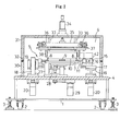
- Fig. 2 is a front view thereof.
- the substrate joining apparatus is configured to join a reinforcing substrate w 2 formed of glass plate serving as a second substrate on a semiconductor wafer (hereinafter, simply referred to as "wafer") w 1 serving as a first substrate.
- a stage frame 4 is disposed on the upper face of a base frame 1 equipped with caster wheels 2 for movement and stands 3 for fixing, and a joining mechanism 5 and an openable/closable decompression chamber 6 accommodating the same are disposed on the stage frame 4.
- the joining mechanism 5 includes a holding table 7 of vacuum adsorption type on which the wafer w 1 is horizontally mounted and held, a pair of right and left side latch claws 8 and a center latch claw 9 that latch and hold the periphery of the reinforcing substrate w 2 at three points, a joining roller 10 that is horizontally hung in the right and left direction and moves fore-and-aft direction, and driving means for these. Concrete structures of each part will be explained below.
- the side latch claws 8 are bolted to a holder 11 in a detachable manner, and are formed stepwise at their tip ends with a latch portion 8a of a partial arc shape that receives and latches a right and left opposing portion in the periphery of the reinforcing substrate w 2 from beneath.
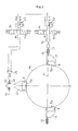
- This latch portion 8a is formed over a certain range in the circumferential direction from right and left diagonal positions passing through the center of the substrate to a starting end side of the joining (lower side in Fig. 3).
- the holder 11 itself is born on a bearing bracket 12 so as to be able to oscillate about a horizontal lateral axial center x 1 passing through the center of the substrate in plane view, and a supporting axis 13 rotatably supported by the bearing bracket 12 is connected to an air-driven rotary actuator 15 via an electromagnetic valve 14.
- the holder 11 is allowed to oscillate only from the horizontal posture to the front down posture, and when the electromagnetic valve 14 is in a neutral position "n" as illustrated, the rotary actuator 15 can freely rotate.
- the rotary actuator 15 drives the holder 11 into the front rising direction, so that the holder 11 and the side latch claws 8 attached thereto are forcedly held in the horizontal posture which is an oscillation limit in the front rising direction.
- the bearing bracket 12 bearing the holder 11 of either right or left side latch claw 8 and the rotary actuator 15 are mounted on a supporting stage 16, and the supporting stage 16 is designed to be laterally movable in the horizontal direction via a linear lateral driving mechanism 17 driven in a screw feeding manner by an air cylinder or a pulse motor.
- the right and left side latch claws 8 are reciprocable between the substrate holding position and the retracted position retracted outside the substrate.
- linear lateral driving mechanism 17 itself is mounted on an elevator stage 19 which is able to move up and down along a rail 18 erected on the stage frame 4, and by moving up and down the elevator stage 19 in a screw feeding manner by means of a pulse motor 20, it is possible to move up and down the right and the left side latch claws 8 respectively as desired.
- the center latch claw 9 is also bolted to a holder 21 in a detachable manner as shown in Fig. 3, and formed stepwise at its tip end with a latch portion 9a of a partial arc shape that receives and latches an edge end on the joining end side of the reinforcing substrate w 2 from beneath over a certain range in the circumferential direction.
- the holder 21 itself is born on a bearing bracket 22 so as to be able to oscillate about a horizontal lateral axial center x 2 in plane view, and a supporting axis 23 rotatably supported by the bearing bracket 22 is connected to an air-driven rotary actuator 25 via an electromagnetic valve 24.
- the holder 21 is allowed to oscillate only from the horizontal posture to the front down position.
- the electromagnetic valve 24 is in a neutral position "n" as illustrated, the rotary actuator 25 can freely rotate, and when the electromagnetic valve 24 is switched to a first position p 1 , the rotary actuator 25 drives the holder 21 into the front rising direction, so that the holder 21 and the center latch claw 9 attached thereto are forcedly held in the horizontal posture which is the oscillation limit in the front rising direction.
- the bearing bracket 22 bearing the holder 21 of the center latch claw 9 and the rotary actuator 25 are also mounted on a supporting stage 26, and the supporting stage 26 is designed to be movable in the fore-and-aft direction via a linear fore-and-aft driving mechanism (not shown) driven in a screw feeding manner by an air cylinder or a pulse motor.
- the center latch claw 9 is reciprocable between the substrate holding position and the retracted position retracted outside the substrate.
- the linear fore-and-aft driving mechanism itself is mounted on an elevator stage 28 which is able to move up and down along a rail 27 erected on the stage frame 4, and by moving up and down the elevator stage 28 in a screw feeding manner by means of a pulse motor 29, it is possible to move up and down the center latch claw 9 as desired.
- the decompression chamber 6 is made up of a fixed peripheral wall 30 of rectangular cylinder shape provided on the stage frame 4 and a cover case 31 attached to the fixed peripheral wall 30 via a hinge (not shown) so as to be able to open/close by oscillation in the vertical direction.
- a vacuum pump (not shown).
- the entire circumference of the upper end of the fixed peripheral wall 30 is attached with a seal 32 for ensuring closeness of the interior by close contact with the entire circumference of the lower end of the closed cover case 31.
- the joining roller 10 is provided in the cover case 31 so as to be movable in the fore-and-aft direction and in the up and down direction.
- the cover case 31 is attached with an elevator frame 35 which is slidable in the up and down direction via four guide axes 33 and is driven to move up and down by the air cylinder 34.
- a movable stage 37 is attached so as to be movable in the fore-and-aft direction along a pair of right and left guide axes 36 that are hung by elevator frame 35 horizontally in the fore-and-aft direction; and the joining roller 10 is rotatably supported horizontally in the right and left direction by a holder 38 that is connected by bolting to the bottom face of the movable stage 37 in a detachable manner.
- a non-slip type belt 41 that is to be rotationally driven by the motor 40 is horizontally wound in the fore-and-aft direction.
- To this belt 41 is connected the movable stage 37, and by driving the movable stage 37 to move horizontally in the fore-and-aft direction by rotating the belt 41 forward or backward, the joining roller 10 is moved horizontally in the fore-and-aft direction.
- the holder 38 of the joining roller 10 is provided with a motor 42 for driving the joining roller 10, the motor 42 auto-rotating while moving the joining roller 10 in the fore-and-aft direction.
- the holding table 7, the side latch claws 8, the center latch claw 9 and the joining roller 10 are also replaced by suitable ones.
- the forward movement velocity of the joining roller 10 may be usually constant, the area where the roller moves may be separated into a plurality of sections, and the forward movement velocity may be changed for each section.
- the reinforcing substrate w 2 having the same diameter as the wafer w 1 is joined was taken as an example, the same operation applies to the case where a reinforcing substrate w 2 having a slightly smaller diameter than the wafer w 1 is joined. Also a reinforcing substrate w 2 having a larger diameter than the wafer w 1 may be joined and, in this case, the side latch claws 8 and the center latch claw 9 may be moved down so as to sink into notch recesses 7a, 7b formed near the circumference of the holding table 7 rather than retracting the side latch claws 8 and the center latch claw 9 outside the substrate.
Landscapes
- Container, Conveyance, Adherence, Positioning, Of Wafer (AREA)
- Folding Of Thin Sheet-Like Materials, Special Discharging Devices, And Others (AREA)
- Dicing (AREA)
Applications Claiming Priority (2)
| Application Number | Priority Date | Filing Date | Title |
|---|---|---|---|
| JP2003274047A JP4330393B2 (ja) | 2003-07-14 | 2003-07-14 | 基板貼合せ方法およびその装置 |
| JP2003274047 | 2003-07-14 |
Publications (2)
| Publication Number | Publication Date |
|---|---|
| EP1498933A2 true EP1498933A2 (de) | 2005-01-19 |
| EP1498933A3 EP1498933A3 (de) | 2006-09-13 |
Family
ID=33475540
Family Applications (1)
| Application Number | Title | Priority Date | Filing Date |
|---|---|---|---|
| EP04015048A Withdrawn EP1498933A3 (de) | 2003-07-14 | 2004-06-26 | Verfahren und Vorrichtung zum Verbinden von Substraten |
Country Status (6)
| Country | Link |
|---|---|
| US (1) | US7078316B2 (de) |
| EP (1) | EP1498933A3 (de) |
| JP (1) | JP4330393B2 (de) |
| KR (1) | KR101059009B1 (de) |
| CN (1) | CN100353504C (de) |
| TW (1) | TWI329342B (de) |
Cited By (1)
| Publication number | Priority date | Publication date | Assignee | Title |
|---|---|---|---|---|
| WO2011151430A3 (de) * | 2010-06-02 | 2012-04-26 | Kuka Systems Gmbh | Fertigungseinrichtung und verfahren |
Families Citing this family (18)
| Publication number | Priority date | Publication date | Assignee | Title |
|---|---|---|---|---|
| JP4698452B2 (ja) * | 2006-03-20 | 2011-06-08 | 日東電工株式会社 | 基板貼合せ方法およびこれを用いた装置 |
| JP4822989B2 (ja) * | 2006-09-07 | 2011-11-24 | 日東電工株式会社 | 基板貼合せ方法およびこれを用いた装置 |
| JP4841412B2 (ja) * | 2006-12-06 | 2011-12-21 | 日東電工株式会社 | 基板貼合せ装置 |
| JP4750724B2 (ja) * | 2007-01-25 | 2011-08-17 | 東京応化工業株式会社 | 重ね合わせユニット及び貼り合わせ装置 |
| KR100994506B1 (ko) | 2008-11-18 | 2010-11-15 | 엘아이지에이디피 주식회사 | 기판 합착기 |
| DE102009018977A1 (de) | 2009-04-25 | 2010-11-04 | Ev Group Gmbh | Vorrichtung zur Ausrichtung und Vorfixierung eines Wafers |
| US20110168317A1 (en) * | 2010-01-12 | 2011-07-14 | Fujifilm Corporation | Controlled Bond Wave Over Patterned Wafer |
| JP5599642B2 (ja) * | 2010-04-20 | 2014-10-01 | 芝浦メカトロニクス株式会社 | 基板処理装置および基板処理方法 |
| JP5851113B2 (ja) * | 2010-04-26 | 2016-02-03 | 株式会社半導体エネルギー研究所 | Soi基板の作製方法 |
| JP2012156163A (ja) * | 2011-01-21 | 2012-08-16 | Toshiba Corp | 半導体製造装置 |
| JP5373008B2 (ja) * | 2011-08-05 | 2013-12-18 | 日東電工株式会社 | 基板貼合せ方法 |
| JP6200232B2 (ja) * | 2013-07-24 | 2017-09-20 | 関西セイキ工業株式会社 | テープ貼付装置 |
| TW201539645A (zh) * | 2014-01-20 | 2015-10-16 | 蘇士微科技印刷術股份有限公司 | 基片保持系統和方法 |
| US10744070B2 (en) | 2015-06-19 | 2020-08-18 | University Of Southern California | Enteral fast access tract platform system |
| CA2990230A1 (en) | 2015-06-19 | 2016-12-22 | University Of Southern California | Compositions and methods for modified nutrient delivery |
| US9944055B2 (en) | 2015-06-26 | 2018-04-17 | Sunpower Corporation | Thermo-compression bonding tool with high temperature elastic element |
| CN106653629B (zh) * | 2016-11-29 | 2019-01-29 | 河南省科学院应用物理研究所有限公司 | 一种减少微系统金属界面封装键合缺陷的方法 |
| WO2025235457A1 (en) | 2024-05-09 | 2025-11-13 | Alsteni Medical, Inc. | Intraoral gastrointestinal access device and related methods |
Family Cites Families (12)
| Publication number | Priority date | Publication date | Assignee | Title |
|---|---|---|---|---|
| JPS6451911A (en) * | 1987-08-21 | 1989-02-28 | Nitto Denko Corp | Sticking device for mounting frame for semiconductor wafer |
| KR970002433B1 (ko) * | 1993-12-31 | 1997-03-05 | 삼성전자 주식회사 | 마스킹 필름의 부착 방법 및 이에 사용되는 마스킹 필름 부착 장치 |
| KR19990028523A (ko) * | 1995-08-31 | 1999-04-15 | 야마모토 히데키 | 반도체웨이퍼의 보호점착테이프의 박리방법 및 그 장치 |
| JPH09148282A (ja) * | 1995-11-28 | 1997-06-06 | Sony Corp | 保護テープ貼り付け装置 |
| US6080263A (en) * | 1997-05-30 | 2000-06-27 | Lintec Corporation | Method and apparatus for applying a protecting film to a semiconductor wafer |
| JP2000349136A (ja) | 1999-06-01 | 2000-12-15 | Lintec Corp | 粘着材の貼付装置及び貼付方法 |
| JP4700160B2 (ja) * | 2000-03-13 | 2011-06-15 | 株式会社半導体エネルギー研究所 | 半導体装置 |
| US20010026349A1 (en) * | 2000-03-31 | 2001-10-04 | Keiichi Furukawa | Method and apparatus for manufacturing liquid crystal panel |
| JP2001281640A (ja) * | 2000-03-31 | 2001-10-10 | Minolta Co Ltd | 液晶パネルの製造方法及び基板貼り合わせ方法 |
| JP2002184847A (ja) * | 2000-12-19 | 2002-06-28 | Nec Kansai Ltd | 貼付装置 |
| JP2003022028A (ja) * | 2001-07-06 | 2003-01-24 | Toyota Industries Corp | 貼り付け装置及び貼り付け方法 |
| JP2003023061A (ja) | 2001-07-09 | 2003-01-24 | Lintec Corp | 貼合装置 |
-
2003
- 2003-07-14 JP JP2003274047A patent/JP4330393B2/ja not_active Expired - Fee Related
-
2004
- 2004-06-25 US US10/875,165 patent/US7078316B2/en not_active Expired - Fee Related
- 2004-06-26 EP EP04015048A patent/EP1498933A3/de not_active Withdrawn
- 2004-06-29 TW TW093118937A patent/TWI329342B/zh not_active IP Right Cessation
- 2004-07-12 KR KR1020040054057A patent/KR101059009B1/ko not_active Expired - Fee Related
- 2004-07-14 CN CNB2004100699474A patent/CN100353504C/zh not_active Expired - Fee Related
Cited By (2)
| Publication number | Priority date | Publication date | Assignee | Title |
|---|---|---|---|---|
| WO2011151430A3 (de) * | 2010-06-02 | 2012-04-26 | Kuka Systems Gmbh | Fertigungseinrichtung und verfahren |
| US8987040B2 (en) | 2010-06-02 | 2015-03-24 | Kuka Systems Gmbh | Manufacturing means and process |
Also Published As
| Publication number | Publication date |
|---|---|
| JP2005039035A (ja) | 2005-02-10 |
| KR20050009171A (ko) | 2005-01-24 |
| KR101059009B1 (ko) | 2011-08-23 |
| JP4330393B2 (ja) | 2009-09-16 |
| US7078316B2 (en) | 2006-07-18 |
| CN100353504C (zh) | 2007-12-05 |
| CN1577761A (zh) | 2005-02-09 |
| TWI329342B (en) | 2010-08-21 |
| EP1498933A3 (de) | 2006-09-13 |
| TW200509239A (en) | 2005-03-01 |
| US20050014345A1 (en) | 2005-01-20 |
Similar Documents
| Publication | Publication Date | Title |
|---|---|---|
| US7078316B2 (en) | Substrate joining apparatus | |
| JP3410983B2 (ja) | 基板の組立方法およびその装置 | |
| US8211261B2 (en) | Semiconductor manufacturing method of die pick-up from wafer | |
| US6951593B2 (en) | Laminating device and laminating method | |
| TWI414037B (zh) | 基板貼合方法及利用該方法之裝置 | |
| JP3411023B2 (ja) | 基板の組立装置 | |
| CN101118842B (zh) | 对半导体晶圆粘贴粘合带、剥离保护带的方法及装置 | |
| EP1665364B1 (de) | Vorrichtung und verfahren zum entfernen eines halbleiterchips | |
| TWI472493B (zh) | The breaking device of the brittle material substrate | |
| EP1232835B1 (de) | Verfahren und Vorrichtung zum Planarisieren einer Halbleiterscheibe | |
| JP7240440B2 (ja) | 粘着テープ貼付け方法および粘着テープ貼付け装置 | |
| JPH11297793A (ja) | チップ突き上げ装置及びそれを用いたダイボンディング装置 | |
| CN217588872U (zh) | 一种晶圆移动扩张平台 | |
| JP2002110626A (ja) | ベベルエッチング装置およびベベルエッチング方法 | |
| JP4158171B2 (ja) | 部材貼り合わせ装置、及び部材貼り合わせ方法 | |
| JP2006222267A (ja) | 基板貼合せ方法およびこれを用いた装置 | |
| JP4822989B2 (ja) | 基板貼合せ方法およびこれを用いた装置 | |
| JPH05338730A (ja) | ウエハリング移載装置 | |
| JP2011238966A (ja) | 基板貼合せ方法 | |
| JP4470923B2 (ja) | 基板組立て装置 | |
| JPH111202A (ja) | 密封式容器の蓋閉め装置 | |
| JP3694688B2 (ja) | 基板組立装置及び基板組立方法 | |
| JPH07204746A (ja) | 板材折曲げ加工機における材料取扱ロボットハンド | |
| KR20230136204A (ko) | 웨이퍼 시트의 초기 박리 발생 방법 및 반도체 다이의 픽업 장치 | |
| JP2000091404A (ja) | ペレット突き上げ装置 |
Legal Events
| Date | Code | Title | Description |
|---|---|---|---|
| PUAI | Public reference made under article 153(3) epc to a published international application that has entered the european phase |
Free format text: ORIGINAL CODE: 0009012 |
|
| AK | Designated contracting states |
Kind code of ref document: A2 Designated state(s): AT BE BG CH CY CZ DE DK EE ES FI FR GB GR HU IE IT LI LU MC NL PL PT RO SE SI SK TR |
|
| AX | Request for extension of the european patent |
Extension state: AL HR LT LV MK |
|
| PUAL | Search report despatched |
Free format text: ORIGINAL CODE: 0009013 |
|
| AK | Designated contracting states |
Kind code of ref document: A3 Designated state(s): AT BE BG CH CY CZ DE DK EE ES FI FR GB GR HU IE IT LI LU MC NL PL PT RO SE SI SK TR |
|
| AX | Request for extension of the european patent |
Extension state: AL HR LT LV MK |
|
| AKX | Designation fees paid |
Designated state(s): AT BE BG CH CY CZ DE DK EE ES FI FR GB GR HU IE IT LI LU MC NL PL PT RO SE SI SK TR |
|
| STAA | Information on the status of an ep patent application or granted ep patent |
Free format text: STATUS: THE APPLICATION IS DEEMED TO BE WITHDRAWN |
|
| 18D | Application deemed to be withdrawn |
Effective date: 20070314 |