EP1502673A1 - Werkzeugmaschine mit Werkzeug-Hubantrieb - Google Patents
Werkzeugmaschine mit Werkzeug-Hubantrieb Download PDFInfo
- Publication number
- EP1502673A1 EP1502673A1 EP03017009A EP03017009A EP1502673A1 EP 1502673 A1 EP1502673 A1 EP 1502673A1 EP 03017009 A EP03017009 A EP 03017009A EP 03017009 A EP03017009 A EP 03017009A EP 1502673 A1 EP1502673 A1 EP 1502673A1
- Authority
- EP
- European Patent Office
- Prior art keywords
- spindle
- drive
- tool
- machine tool
- tool holder
- Prior art date
- Legal status (The legal status is an assumption and is not a legal conclusion. Google has not performed a legal analysis and makes no representation as to the accuracy of the status listed.)
- Granted
Links
- 238000004080 punching Methods 0.000 claims description 49
- 239000011159 matrix material Substances 0.000 abstract description 3
- 239000002699 waste material Substances 0.000 description 4
- 230000008878 coupling Effects 0.000 description 2
- 238000010168 coupling process Methods 0.000 description 2
- 238000005859 coupling reaction Methods 0.000 description 2
- 230000000694 effects Effects 0.000 description 2
- 238000003698 laser cutting Methods 0.000 description 2
- 238000003754 machining Methods 0.000 description 2
- 101100390736 Danio rerio fign gene Proteins 0.000 description 1
- 101100390738 Mus musculus Fign gene Proteins 0.000 description 1
- 230000001133 acceleration Effects 0.000 description 1
- 230000005540 biological transmission Effects 0.000 description 1
- 238000010276 construction Methods 0.000 description 1
- 230000001419 dependent effect Effects 0.000 description 1
- 230000005484 gravity Effects 0.000 description 1
- 210000003800 pharynx Anatomy 0.000 description 1
Images



Classifications
-
- B—PERFORMING OPERATIONS; TRANSPORTING
- B21—MECHANICAL METAL-WORKING WITHOUT ESSENTIALLY REMOVING MATERIAL; PUNCHING METAL
- B21D—WORKING OR PROCESSING OF SHEET METAL OR METAL TUBES, RODS OR PROFILES WITHOUT ESSENTIALLY REMOVING MATERIAL; PUNCHING METAL
- B21D28/00—Shaping by press-cutting; Perforating
- B21D28/02—Punching blanks or articles with or without obtaining scrap; Notching
- B21D28/20—Applications of drives for reducing noise or wear
-
- Y—GENERAL TAGGING OF NEW TECHNOLOGICAL DEVELOPMENTS; GENERAL TAGGING OF CROSS-SECTIONAL TECHNOLOGIES SPANNING OVER SEVERAL SECTIONS OF THE IPC; TECHNICAL SUBJECTS COVERED BY FORMER USPC CROSS-REFERENCE ART COLLECTIONS [XRACs] AND DIGESTS
- Y10—TECHNICAL SUBJECTS COVERED BY FORMER USPC
- Y10T—TECHNICAL SUBJECTS COVERED BY FORMER US CLASSIFICATION
- Y10T29/00—Metal working
- Y10T29/49—Method of mechanical manufacture
- Y10T29/49995—Shaping one-piece blank by removing material
-
- Y—GENERAL TAGGING OF NEW TECHNOLOGICAL DEVELOPMENTS; GENERAL TAGGING OF CROSS-SECTIONAL TECHNOLOGIES SPANNING OVER SEVERAL SECTIONS OF THE IPC; TECHNICAL SUBJECTS COVERED BY FORMER USPC CROSS-REFERENCE ART COLLECTIONS [XRACs] AND DIGESTS
- Y10—TECHNICAL SUBJECTS COVERED BY FORMER USPC
- Y10T—TECHNICAL SUBJECTS COVERED BY FORMER US CLASSIFICATION
- Y10T83/00—Cutting
- Y10T83/04—Processes
-
- Y—GENERAL TAGGING OF NEW TECHNOLOGICAL DEVELOPMENTS; GENERAL TAGGING OF CROSS-SECTIONAL TECHNOLOGIES SPANNING OVER SEVERAL SECTIONS OF THE IPC; TECHNICAL SUBJECTS COVERED BY FORMER USPC CROSS-REFERENCE ART COLLECTIONS [XRACs] AND DIGESTS
- Y10—TECHNICAL SUBJECTS COVERED BY FORMER USPC
- Y10T—TECHNICAL SUBJECTS COVERED BY FORMER US CLASSIFICATION
- Y10T83/00—Cutting
- Y10T83/869—Means to drive or to guide tool
- Y10T83/8745—Tool and anvil relatively positionable
-
- Y—GENERAL TAGGING OF NEW TECHNOLOGICAL DEVELOPMENTS; GENERAL TAGGING OF CROSS-SECTIONAL TECHNOLOGIES SPANNING OVER SEVERAL SECTIONS OF THE IPC; TECHNICAL SUBJECTS COVERED BY FORMER USPC CROSS-REFERENCE ART COLLECTIONS [XRACs] AND DIGESTS
- Y10—TECHNICAL SUBJECTS COVERED BY FORMER USPC
- Y10T—TECHNICAL SUBJECTS COVERED BY FORMER US CLASSIFICATION
- Y10T83/00—Cutting
- Y10T83/869—Means to drive or to guide tool
- Y10T83/8821—With simple rectilinear reciprocating motion only
- Y10T83/8835—And means to move cooperating cutting member
-
- Y—GENERAL TAGGING OF NEW TECHNOLOGICAL DEVELOPMENTS; GENERAL TAGGING OF CROSS-SECTIONAL TECHNOLOGIES SPANNING OVER SEVERAL SECTIONS OF THE IPC; TECHNICAL SUBJECTS COVERED BY FORMER USPC CROSS-REFERENCE ART COLLECTIONS [XRACs] AND DIGESTS
- Y10—TECHNICAL SUBJECTS COVERED BY FORMER USPC
- Y10T—TECHNICAL SUBJECTS COVERED BY FORMER US CLASSIFICATION
- Y10T83/00—Cutting
- Y10T83/929—Tool or tool with support
- Y10T83/9411—Cutting couple type
- Y10T83/9423—Punching tool
-
- Y—GENERAL TAGGING OF NEW TECHNOLOGICAL DEVELOPMENTS; GENERAL TAGGING OF CROSS-SECTIONAL TECHNOLOGIES SPANNING OVER SEVERAL SECTIONS OF THE IPC; TECHNICAL SUBJECTS COVERED BY FORMER USPC CROSS-REFERENCE ART COLLECTIONS [XRACs] AND DIGESTS
- Y10—TECHNICAL SUBJECTS COVERED BY FORMER USPC
- Y10T—TECHNICAL SUBJECTS COVERED BY FORMER US CLASSIFICATION
- Y10T83/00—Cutting
- Y10T83/929—Tool or tool with support
- Y10T83/9457—Joint or connection
- Y10T83/9473—For rectilinearly reciprocating tool
- Y10T83/9476—Tool is single element with continuous cutting edge [e.g., punch, etc.]
Definitions
- the invention relates to a machine tool with at least one Tool holder to which a punching tool can be arranged is as well as with a tool-lifting drive, by means of which Tool holder to the work area of the machine tool back and forth in a stroke direction is movable, the Tool holder one to the working area of the machine tool towards opening and in the stroke direction permeable opening having.
- Such a machine tool is disclosed in EP 0 417 836 B1.
- the prior art relates to a punching machine with a raisable and lowerable die.
- the lifting movement of the die is generated by means of a tool lifting drive, in turn a hydraulic piston-cylinder unit and a wedge gear includes.
- the piston-cylinder unit is arranged horizontally and moves a first gear wedge of the wedge in horizontal Direction.
- the first gear wedge is at his after top-facing side with an inclined to the horizontal Provided wedge surface.
- At this wedge surface of the first gear wedge is a second gear wedge of the wedge gear with a supported corresponding wedge surface.
- the second gear wedge superimposed on its top a die holder and over this the die to be raised or lowered.
- the wedge gear By means of the wedge gear is the horizontally directed drive movement of Piston-cylinder unit in a vertical movement of the die implemented.
- the die holder In addition to the matrix are also the die holder as well the gear wedges of the wedge gear in the vertical direction permeable openings provided by which, for example at the processing point resulting punching waste the work area leave the machine.
- the tool lift drive is built the previously known punching machine and thus also the Punching machine itself relatively large.
- the machine tool according to claim 1 is therefore a tool lifting drive provided with a spindle drive, whose at least one spindle extends in the stroke direction.
- a is in the stroke direction continuing in the opening of the tool holder Passage released.
- the accessibility of the work area the machine tool or the machining tool through the Tool holder through is consequently by the presence of the tool lifting drive is not affected.
- the passage can for example be installed in the tool holder Punching die serve to punching waste from the work area remove the machine tool.
- the spindle drive according to the invention
- Machine tools several spindle-spindle nut units include around the hole in the tool holder continuing passage are arranged around. It is too in the context of the invention conceivable, a spindle-spindle nut unit with a hollow spindle forming said passage provide and beyond at least one other spindle-spindle nut unit spaced from the passage to arrange.
- the mentioned multi-spindle solutions are generally characterized a high dynamic. They allow it, fast short strokes perform the tool holder with high accelerations.
- the use of a plurality of spindle-spindle nut units allows the transmission is particularly large Forces.
- this even with the strokes to be carried out as rotation of the tool holder or one with the Tool holder provided housing can be used. elaborate Measures to prevent rotation are unnecessary accordingly. This circumstance in turn contributes to a compact design the overall arrangement.
- the aforementioned drive ring gears with inner recess are in Interest in a compact design of the rotary drive and thus provided the entire tool lifting drive.
- a special space-saving arrangement results when a drive ring gear one or more spindle-spindle nut units without intermediate gear drives (claim 5). In this case needs it between the drive ring gear and the one or more concerned Spindle spindle nut units of only one coupling.
- Conceivable are elastic as well as rigid, switchable as well as non-switchable couplings.
- a special compactness of the tool lifting drive results itself, when the drive ring gear from the rotor as a drive motor for the tool lifting drive electric motor is formed (claim 6). Especially when as an electric motor a torque motor can be used on the or the spindle drives high torques without intermediate gear be transmitted.
- the drive ring gear surrounds the at least one spindle-spindle nut unit to be driven.
- the compact tool lifting drive according to the invention of machine tools can be used in particular for driving punch punches and / or of punching dies (claim 10).
- Strokes can be both working strokes for punching workpiece machining as well as parking strokes for positioning the concerned Punching tool to be executed.
- a punching machine 1 has a C-shaped machine frame 2 with an upper frame leg 3 and a lower frame legs 4. At the free end of the upper frame leg 3 is a punch 5 in one by one Double arrow illustrated lifting direction 6 can be raised and lowered. Causes the lifting movement of the punch 5 by means of a hereinafter described in detail tool lifting drive.
- the punch 5 opposite is at the free end of the lower frame leg 4 a punching die 7 is arranged. Also this is explained in more detail below by means of one Tool lifting drive in der.Hubraum 6 movable. Both the Punch 5 and the punching die 7 are one in the Lifting direction 6 extending axis of rotation in the direction of a double arrow 8 turnable. Both the rotation adjustment as well the lifting movement of the punch 5 and the punching die 7 take place numerically controlled.
- a collecting container 9 provided for punching waste.
- Finished parts are integrated into a workpiece table 10 via a and in the direction of a double arrow 11 back and forth pivotable flap 12 from the work area of the punching machine 1 discharged.
- a sheet 13 which passes through a space between the pharynx the upper frame leg 3 and the lower frame legs 4 accommodated coordinate guide 14 in known Way against the punch 5 and the punching die 7 is positioned becomes.
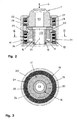
- a tool lifting drive of the first type is a tool lifting drive 15 in detail in Figs. 2 and 3 shown. He includes a spindle drive 16 with a spindle-spindle nut unit 17 and a rotary drive provided for this purpose 18. Parts of Spindle spindle nut unit 17 are designed as a hollow spindle Spindle 19 and a spindle nut 20. The spindle 19 runs with an axis 21 in the stroke direction 6. It is on a housing 22 of the tool lifting drive 15 about the axis 21st rotatable and non-displaceably mounted in the direction of the axis 21. In its interior, it has one open at both axial ends Inner recess 23 on.
- the rotary drive 18 for the spindle-spindle nut unit 17 is electromotive type.
- a torque motor 24 serves as a drive motor and is connected to a stator 25 on the housing 22 of the Tool Hubantriebes 15 stored.
- a rotor 26 of the torque motor 24 runs around the axis 21 of the spindle 19 and is at a Outer flange of the spindle 19 rigidly coupled with this.
- One in Fig. 2 recognizable housing of the torque motor 24 is shown in FIG. 3 not shown for the sake of simplicity.
- the spindle nut 20 of the spindle-spindle nut unit 17 is with a tool holder 27 for the punching die 7 drivingly connected.
- a corresponding positive connection 28 between the spindle nut 20 and the tool holder 27 is in the direction the axis 21 of the spindle 19 and thus in the stroke direction. 6 effective.
- An entrainment of the tool holder 27 and the spindle nut 20 through the spindle 21 revolving around the axis 19 is by a not shown in detail rotation of the Tool holder 27 prevents.
- a rotary adjustment movement of However, tool holder 27 about the axis 21 of the spindle 19 can be performed by means of a servomotor 29.
- the servomotor 29 is used to adjust the punching die 7 in the direction of Double arrow 8 in Fig. 1. In the rotary adjustment of the tool holder 27 and the punching die 7 is the rotation of the Tool holder 27 disabled.
- the punching die 7 in the lifting direction 6 can be raised and lowered.
- the punching die 7 shown in their upper end position. This position takes the punching die 7 in the punching processing of Sheet 13. Is after creating a punched the Sheet 13 by means of the coordinate guide 14 against the punch 5 and the punching die 7 to move, so will the Punching die 7 lowered by means of the tool lifting drive 15. In this way it is avoided that the sheet 13 at his subsequent movement by means of coordinate guidance 14 on its underside with the punching die 7 is in contact and as a result scratches on the underside of the sheet 13 form. It is also conceivable to use the tool lifting drive 15 for the execution of the punching processing of the sheet 13 required strokes. In this case is the relative movement between punch 5 and punching die 7 at 6 in the stroke direction stationary punches. 5 generated by lifting movement of the punching die 7.
- a tool lift drive of the second type for lifting and lowering the punching die 7 show the figures 4 and 5 in the form of a Tool Hubantriebes 30.
- This includes a spindle drive 31st with a total of eight spindle spindle nut units 32 and one Rotary drive 33.
- Each of the spindle-spindle nut units 32 has a spindle 34 and a seated thereon spindle nut 35.
- axes 36 of the spindles 34 extend in the stroke direction 6.
- the spindles 34 On a housing 37 of the tool lifting drive 30, the spindles 34 to their axes 36 rotatably mounted and immovable in the axial direction.
- Each of the spindles 34 is provided with an externally toothed outer collar 38 provided.
- a torque motor 39 with a stator 40 and a rotor 41.
- the latter runs around an axis extending in the stroke direction 6 and meshes with an internal toothing 42 with the external teeth the outer collar 38 on the spindles 34.
- a drive ring gear with internal recess.
- An opening 45 in the interior of the tool holder 27 is aligned according to the fig. 2 and 3 with the passage forming an inner recess 23 provided there spindle 19, in the case of Conditions according to FIGS. 4 and 5 with a passage in the form a free space 46, around which the spindle-spindle nut units 32 are arranged and enclosed by the torque motor 39 becomes.
- Through the opening 45 of the tool holder 27th and the inner recess 23 of the spindle 19 and the free space 46th between the spindle-spindle nut units 32 may in the Processing of the sheet 13 produced punching waste under gravity leave the working area of the punching machine 1.
- the tool lifting drive 15 according to FIGS. 2 and 3 can also the tool lifting drive 30 according to FIGS. 4 and 5 both a feed movement as well as a working stroke of the punching die 7 effect.
- tool lifting drive 47 and a in Fig. 7 shown tool lifting drive 48 are used to move the Punch 5 in the stroke direction 6.
- the Tool lifting drive 48 for the punch 5 is essentially identical to the tool lifting drive 30 for the punching die 7.
- components of the tool lifting drives 47, 48 are the same reference numerals as used for the corresponding Components of the tool lifting drives 15, 30.
Landscapes
- Engineering & Computer Science (AREA)
- Mechanical Engineering (AREA)
- Punching Or Piercing (AREA)
- Press Drives And Press Lines (AREA)
- Perforating, Stamping-Out Or Severing By Means Other Than Cutting (AREA)
- Laser Beam Processing (AREA)
- Automatic Tool Replacement In Machine Tools (AREA)
- Structures Of Non-Positive Displacement Pumps (AREA)
Abstract
Description
- Fig. 1
- eine Stanzmaschine mit Stanzmatrize und Stanzstempel in stark schematisierter, teilgeschnittener Gesamtdarstellung,
- Fig. 2
- einen Längsschnitt eines Hubantriebes erster Bauart für die Stanzmatrize nach Fig. 1,
- Fig. 3
- einen Querschnitt des Hubantriebes nach Fig. 2 mit einer in Fig. 2 senkrecht zu der Zeichenebene und in Richtung der Linie III-III verlaufenden Schnittebene,
- Fig. 4
- einen Längsschnitt eines Hubantriebes zweiter Bauart für die Stanzmatrize nach Fig. 1,
- Fig. 5
- einen Querschnitt des Hubantriebes nach Fig. 4 mit einer in Fig. 4 senkrecht zu der Zeichenebene und in Richtung der Linie V-V verlaufenden Schnittebene,
- Fig. 6
- einen Längsschnitt eines Hubantriebes erster Bauart für den Stanzstempel nach Fig. 1 und
- Fig. 7
- einen Längsschnitt eines Hubantriebes zweiter Bauart für den Stanzstempel nach Fig. 1.
Claims (10)
- Werkzeugmaschine mit wenigstens einer Werkzeughalterung (27), an welcher ein Stanzwerkzeug anordenbar ist sowie mit einem Werkzeug-Hubantrieb (15, 30, 47, 48), mittels dessen die Werkzeughalterung (27) zu dem Arbeitsbereich der Werkzeugmaschine hin und zurück in einer Hubrichtung (6) bewegbar ist, wobei die Werkzeughalterung (27) eine zu dem Arbeitsbereich der Werkzeugmaschine hin mündende und in Hubrichtung (6) durchlässige Öffnung (45) aufweist, dadurch gekennzeichnet, dass der Werkzeug-Hubantrieb (15, 30, 47, 48) einen Spindeltrieb (16, 31) sowie einen Drehantrieb (18, 33) hierfür umfasst, wobei der Spindeltrieb (16, 31) wenigstens eine Spindel-Spindelmutter-Einheit (17, 32) mit einer mit ihrer Achse (21, 36) in Hubrichtung (6) verlaufenden Spindel (19, 34) sowie einer darauf aufsitzenden Spindelmutter (20, 35) aufweist und die Spindel (19, 34) sowie die Spindelmutter (20, 35) der Spindel-Spindelmutter-Einheit (17, 32) mittels des Drehantriebes (18, 33) relativ zueinander um die Achse (21, 36) der Spindel (19, 34) drehbar und dadurch unter Antreiben der Werkzeughalterung (27) in Richtung der Achse (21, 36) der Spindel (19, 34) relativ zueinander in dieser Richtung bewegbar sind und wobei der Spindeltrieb (16, 31) und/oder der Drehantrieb (18, 33) einen sich in Hubrichtung (6) in der Öffnung (45) der Werkzeughalterung (27) fortsetzenden Durchlass freilässt.
- Werkzeugmaschine nach Anspruch 1, dadurch gekennzeichnet, dass der Spindeltrieb (16) eine Spindel-Spindelmutter-Einheit (17) mit einer Spindel (19) aufweist, die als Hohlspindel mit einer Innenaussparung (23) ausgebildet ist, wobei die Innenaussparung (23) der Hohlspindel einen sich in Hubrichtung (6) in der Öffnung (45) der Werkzeughalterung (27) fortsetzenden Durchlass ausbildet.
- Werkzeugmaschine nach einem der vorhergehenden Ansprüche, dadurch gekennzeichnet, dass der Spindeltrieb (31) eine Mehrzahl von Spindel-Spindelmutter-Einheiten (32) aufweist und dass diese Spindel-Spindelmutter-Einheiten (32) unter Freilassen eines sich in Hubrichtung (6) in der Öffnung (45) der Werkzeughalterung (27) fortsetzenden Durchlasses um diesen Durchlass herum angeordnet sind.
- Werkzeugmaschine nach einem der vorhergehenden Ansprüche, dadurch gekennzeichnet, dass der Drehantrieb (18, 33) wenigstens ein Antriebs-Hohlrad mit einer Innenaussparung umfasst, wobei das Antriebs-Hohlrad mit seiner Achse in Hubrichtung (6) verläuft und wenigstens eine Spindel-Spindelmutter-Einheit (17, 32) antreibt und wobei die Innenaussparung des Antriebs-Hohlrades einen sich in Hubrichtung in der Öffnung (45) der Werkzeughalterung (27) fortsetzenden Durchlass freilässt.
- Werkzeugmaschine nach einem der vorhergehenden Ansprüche, dadurch gekennzeichnet, dass das Antriebs-Hohlrad mit der Spindel (19, 34) oder der Spindelmutter (20, 35) wenigstens einer Spindel-Spindelmutter-Einheit (17, 32) ohne Zwischengetriebe antriebsverbunden ist.
- Werkzeugmaschine nach einem der vorhergehenden Ansprüche, dadurch gekennzeichnet, dass das Antriebs-Hohlrad von einem Rotor (26, 41) eines Elektromotors, vorzugsweise von dem Rotor (26, 41) eines Torque-Motors (24, 39), ausgebildet ist.
- Werkzeugmaschine nach einem der vorhergehenden Ansprüche, dadurch gekennzeichnet, dass das Antriebs-Hohlrad die wenigstens eine anzutreibende Spindel-Spindelmutter-Einheit (17, 32) umgreift.
- Werkzeugmaschine nach einem der vorhergehenden Ansprüche, dadurch gekennzeichnet, dass das Antriebs-Hohlrad eine Mehrzahl von Spindel-Spindelmutter-Einheiten (17, 32) umgreift und diese über seine Innenwand gemeinschaftlich antreibt.
- Werkzeugmaschine nach einem der vorhergehenden Ansprüche, dadurch gekennzeichnet, dass das Antriebs-Hohlrad als Sonnenrad innerhalb einer Mehrzahl von Spindel-Spindelmutter-Einheiten (17, 32) angeordnet ist und diese über seine Außenwand gemeinschaftlich antreibt.
- Werkzeugmaschine nach einem der vorhergehenden Ansprüche, dadurch gekennzeichnet, dass an einer Werkzeughalterung (27) als Stanzwerkzeug ein Stanzstempel (5) und/oder dass an einer Werkzeughalterung (27) als Stanzwerkzeug eine Stanzmatrize (7) anordenbar ist.
Priority Applications (7)
| Application Number | Priority Date | Filing Date | Title |
|---|---|---|---|
| AT03017009T ATE324199T1 (de) | 2003-07-26 | 2003-07-26 | Werkzeugmaschine mit werkzeug-hubantrieb |
| EP20030017009 EP1502673B1 (de) | 2003-07-26 | 2003-07-26 | Werkzeugmaschine mit Werkzeug-Hubantrieb |
| DE50303112T DE50303112D1 (de) | 2003-07-26 | 2003-07-26 | Werkzeugmaschine mit Werkzeug-Hubantrieb |
| JP2006521410A JP4681549B2 (ja) | 2003-07-26 | 2004-06-26 | 工具用行程駆動装置を備えた工作機械 |
| PCT/EP2004/006948 WO2005016573A1 (de) | 2003-07-26 | 2004-06-26 | Werkzeugmaschine mit werkzeug-hubantrieb |
| US11/341,861 US8001877B2 (en) | 2003-07-26 | 2006-01-26 | Tool holding system |
| US13/213,822 US8413558B2 (en) | 2003-07-26 | 2011-08-19 | Tool holding system |
Applications Claiming Priority (1)
| Application Number | Priority Date | Filing Date | Title |
|---|---|---|---|
| EP20030017009 EP1502673B1 (de) | 2003-07-26 | 2003-07-26 | Werkzeugmaschine mit Werkzeug-Hubantrieb |
Publications (2)
| Publication Number | Publication Date |
|---|---|
| EP1502673A1 true EP1502673A1 (de) | 2005-02-02 |
| EP1502673B1 EP1502673B1 (de) | 2006-04-26 |
Family
ID=33522281
Family Applications (1)
| Application Number | Title | Priority Date | Filing Date |
|---|---|---|---|
| EP20030017009 Expired - Lifetime EP1502673B1 (de) | 2003-07-26 | 2003-07-26 | Werkzeugmaschine mit Werkzeug-Hubantrieb |
Country Status (6)
| Country | Link |
|---|---|
| US (2) | US8001877B2 (de) |
| EP (1) | EP1502673B1 (de) |
| JP (1) | JP4681549B2 (de) |
| AT (1) | ATE324199T1 (de) |
| DE (1) | DE50303112D1 (de) |
| WO (1) | WO2005016573A1 (de) |
Cited By (5)
| Publication number | Priority date | Publication date | Assignee | Title |
|---|---|---|---|---|
| DE102006014705B3 (de) * | 2006-03-30 | 2007-07-05 | Krauss-Maffei Kunststofftechnik Gmbh | Stanzvorrichtung, insbesondere für Kunststoffformteile |
| EP1839768A1 (de) * | 2006-03-31 | 2007-10-03 | Campex SRL | Stanzpresse, insbesondere zur Ablängung und Endenbearbeitung von Flachstabmaterial für Fensterbeschläge |
| EP1974835A1 (de) | 2007-03-24 | 2008-10-01 | KrausMaffei Technologies GmbH | Stanzschieber, insbesondere zur Verwendung bei einer Stanzvorrichtung |
| CN109513800A (zh) * | 2018-10-22 | 2019-03-26 | 南京工业大学 | 一种数控转塔冲床差动式电冲头机构 |
| US10245633B2 (en) | 2014-05-19 | 2019-04-02 | Trumpf Werkzeugmaschinen Gmbh + Co. Kg | Machining plate-like workpieces |
Families Citing this family (11)
| Publication number | Priority date | Publication date | Assignee | Title |
|---|---|---|---|---|
| ATE396805T1 (de) * | 2004-05-27 | 2008-06-15 | Trumpf Werkzeugmaschinen Gmbh | Stanzmaschine mit elektrischem dreh-/hubantrieb |
| EP2078585B1 (de) * | 2008-01-12 | 2015-03-04 | Trumpf Maschinen AG | Maschinelle Vorrichtung zur Montage und/oder zur Demontage einer Laserdüse sowie Laserbearbeitungsmaschine mit einer derartigen maschinellen Vorrichtung |
| ATE464970T1 (de) * | 2008-01-12 | 2010-05-15 | Trumpf Maschinen Ag | Maschinelle vorrichtung zur montage und/oder zur demontage einer laserdüse sowie laserbearbeitungsmaschine mit einer derartigen maschinellen vorrichtung |
| DE502008000434D1 (de) * | 2008-02-22 | 2010-04-22 | Trumpf Werkzeugmaschinen Gmbh | Werkzeugmaschine zum Schneiden und/oder Umformen von plattenartigen Werkstücken |
| EP2319635B1 (de) | 2009-11-10 | 2014-09-17 | TRUMPF Werkzeugmaschinen GmbH & Co. KG | Pressenantrieb und Verfahren zum Erzeugen einer Hubbewegung einer Werkzeuglagerung mittels eines Pressenantriebs |
| DE102009060826A1 (de) * | 2009-12-29 | 2011-06-30 | SMS Siemag AG, 40237 | Regelung der Seitenführung eines Metallbandes |
| DE102009060823A1 (de) * | 2009-12-29 | 2011-06-30 | SMS Siemag AG, 40237 | Regelung von Seitenführungen eines Metallbandes |
| ES2372377B2 (es) * | 2010-06-25 | 2012-10-25 | Fineblanking Press Systems, S.L. | Prensa de estampación. |
| EP2502716B1 (de) * | 2011-03-21 | 2013-11-06 | TRUMPF Werkzeugmaschinen GmbH + Co. KG | Werkzeug für eine Blechbearbeitungsmaschine und Verfahren zum Trennen einer Folie |
| JP6061764B2 (ja) * | 2013-04-16 | 2017-01-18 | 株式会社アマダホールディングス | パンチプレス |
| EP3213835B1 (de) | 2013-05-27 | 2018-12-26 | SALVAGNINI ITALIA S.p.A. | Stanzvorrichtung |
Citations (3)
| Publication number | Priority date | Publication date | Assignee | Title |
|---|---|---|---|---|
| EP0417836A1 (de) * | 1989-09-12 | 1991-03-20 | HOLDING M. BROUWER & CO. B.V. | Stanzmaschine |
| EP0809550A1 (de) * | 1995-12-14 | 1997-12-03 | Lillbacka Jetair Oy | Metallblecharbeitsstation |
| EP0873854A1 (de) * | 1997-04-25 | 1998-10-28 | Lillbacka Jetair Oy | Antrieb für Pressvorrichtung |
Family Cites Families (17)
| Publication number | Priority date | Publication date | Assignee | Title |
|---|---|---|---|---|
| JPS59157728A (ja) | 1983-02-27 | 1984-09-07 | Rohm Co Ltd | 電流反転回路 |
| JPS59157728U (ja) * | 1983-12-22 | 1984-10-23 | 株式会社 アマダ | タレツトパンチプレス |
| JPH03186490A (ja) * | 1989-12-15 | 1991-08-14 | Suzuki Motor Corp | 自動2輪車のフレーム |
| JPH07108425B2 (ja) * | 1990-03-23 | 1995-11-22 | 株式会社小松製作所 | パンチプレス |
| JPH04258326A (ja) * | 1991-02-05 | 1992-09-14 | Murata Mach Ltd | タレットパンチプレス |
| DE4106685C1 (de) * | 1991-03-02 | 1992-04-30 | Mercedes-Benz Aktiengesellschaft, 7000 Stuttgart, De | |
| DE4109685A1 (de) * | 1991-03-23 | 1992-09-24 | Siempelkamp Pressen Sys Gmbh | Spindelpresse |
| SE469111B (sv) * | 1991-05-30 | 1993-05-17 | Pullmax Ab | Anordning vid verktygsmagasin foer plaatbearbetningsmaskiner |
| JP3454877B2 (ja) * | 1993-09-27 | 2003-10-06 | 株式会社アマダ | パンチングマシン |
| JPH081399A (ja) * | 1994-06-17 | 1996-01-09 | Unisia Jecs Corp | 安全機構付プレス装置 |
| JP3186490B2 (ja) | 1995-02-28 | 2001-07-11 | 松下電器産業株式会社 | 多重伝送方式エンコーダ |
| JP3787900B2 (ja) * | 1995-07-20 | 2006-06-21 | 株式会社日立製作所 | 金属板の逐次張出し成形装置 |
| JP2000317689A (ja) * | 1999-05-17 | 2000-11-21 | Amada Eng Center Co Ltd | プレス機におけるモータ機構の取付方法及び取付構造 |
| JP4785238B2 (ja) * | 2000-11-06 | 2011-10-05 | 株式会社アマダエンジニアリングセンター | パンチプレス |
| JP2002192385A (ja) * | 2000-12-28 | 2002-07-10 | Unisia Jecs Corp | 電動式押圧装置 |
| DE10133165A1 (de) * | 2001-07-07 | 2003-01-16 | Bosch Gmbh Robert | Presse zum Ausführen von Preßvorgängen an Werkstücken |
| JP4258326B2 (ja) | 2003-09-11 | 2009-04-30 | 株式会社Ihi | 炭化物処理方法及び装置 |
-
2003
- 2003-07-26 AT AT03017009T patent/ATE324199T1/de active
- 2003-07-26 DE DE50303112T patent/DE50303112D1/de not_active Expired - Lifetime
- 2003-07-26 EP EP20030017009 patent/EP1502673B1/de not_active Expired - Lifetime
-
2004
- 2004-06-26 WO PCT/EP2004/006948 patent/WO2005016573A1/de not_active Ceased
- 2004-06-26 JP JP2006521410A patent/JP4681549B2/ja not_active Expired - Lifetime
-
2006
- 2006-01-26 US US11/341,861 patent/US8001877B2/en active Active
-
2011
- 2011-08-19 US US13/213,822 patent/US8413558B2/en not_active Expired - Fee Related
Patent Citations (3)
| Publication number | Priority date | Publication date | Assignee | Title |
|---|---|---|---|---|
| EP0417836A1 (de) * | 1989-09-12 | 1991-03-20 | HOLDING M. BROUWER & CO. B.V. | Stanzmaschine |
| EP0809550A1 (de) * | 1995-12-14 | 1997-12-03 | Lillbacka Jetair Oy | Metallblecharbeitsstation |
| EP0873854A1 (de) * | 1997-04-25 | 1998-10-28 | Lillbacka Jetair Oy | Antrieb für Pressvorrichtung |
Cited By (5)
| Publication number | Priority date | Publication date | Assignee | Title |
|---|---|---|---|---|
| DE102006014705B3 (de) * | 2006-03-30 | 2007-07-05 | Krauss-Maffei Kunststofftechnik Gmbh | Stanzvorrichtung, insbesondere für Kunststoffformteile |
| EP1839768A1 (de) * | 2006-03-31 | 2007-10-03 | Campex SRL | Stanzpresse, insbesondere zur Ablängung und Endenbearbeitung von Flachstabmaterial für Fensterbeschläge |
| EP1974835A1 (de) | 2007-03-24 | 2008-10-01 | KrausMaffei Technologies GmbH | Stanzschieber, insbesondere zur Verwendung bei einer Stanzvorrichtung |
| US10245633B2 (en) | 2014-05-19 | 2019-04-02 | Trumpf Werkzeugmaschinen Gmbh + Co. Kg | Machining plate-like workpieces |
| CN109513800A (zh) * | 2018-10-22 | 2019-03-26 | 南京工业大学 | 一种数控转塔冲床差动式电冲头机构 |
Also Published As
| Publication number | Publication date |
|---|---|
| ATE324199T1 (de) | 2006-05-15 |
| US20060144831A1 (en) | 2006-07-06 |
| WO2005016573A1 (de) | 2005-02-24 |
| US8001877B2 (en) | 2011-08-23 |
| JP2007500078A (ja) | 2007-01-11 |
| US20120037605A1 (en) | 2012-02-16 |
| US8413558B2 (en) | 2013-04-09 |
| DE50303112D1 (de) | 2006-06-01 |
| JP4681549B2 (ja) | 2011-05-11 |
| EP1502673B1 (de) | 2006-04-26 |
Similar Documents
| Publication | Publication Date | Title |
|---|---|---|
| DE102011015570B4 (de) | Biegekopf zum Biegen stab- und rohrförmiger Werkstücke | |
| EP3943239B1 (de) | Werkzeugmaschine und verfahren zum betreiben der werkzeugmaschine | |
| EP1502673B1 (de) | Werkzeugmaschine mit Werkzeug-Hubantrieb | |
| EP2527058B1 (de) | Werkzeugmaschine in Form einer Presse zum Bearbeiten von Werkstücken, insbesondere von Blechen | |
| DE3536323C2 (de) | Stanz-Gewindebohrmaschine | |
| EP2321082B1 (de) | Vorrichtung zur erzeugung eines gewindes | |
| DE69612648T2 (de) | Bearbeitungsmaschine die einen Knick zwischen Werkzeug und Stück vermindert | |
| EP1600225B1 (de) | Stanzmaschine mit elektrischem Dreh-/Hubantrieb | |
| EP3778118A1 (de) | Werkzeugmaschine mit zwei arbeitsspindeln | |
| DE102008060043B3 (de) | Spindelpresse | |
| EP2329944B1 (de) | Presse zum Erzeugen einer Druckkraft für die Bearbeitung eines Werkstückes | |
| DE1213704B (de) | Nach dem Abwaelzverfahren und mit schrittweiser Teilschaltbewegung arbeitende Verzahnungsmaschine | |
| DE102010028678B4 (de) | Werkzeughalterung, Werkzeugmaschine mit einer derartigen Werkzeughalterung sowie Verfahren zum Festlegen eines Bearbeitungswerkzeuges an einer Werkzeughalterung einer Werkzeugmaschine | |
| DE10252086B4 (de) | Werkzeugmaschine, insbesondere Fräsmaschine, sowie Verfahren zum Betrieb einer solchen Werkzeugmaschine | |
| DE1552227A1 (de) | Werkzeugmaschine mit einem Schlitten zur Aufnahme einer umlaufenden Werkzeugspindel | |
| AT510052B1 (de) | Antriebseinheit für einen stanzautomat oder eine presse | |
| EP2165793B1 (de) | Maschine zum Bearbeiten von plattenartigen Werkstücken, insbesondere von Blechen sowie Werkzeugsatz für eine derartige Maschine und Verwendung eines Gewindefräswerkzeugs an einer derartigen Maschine | |
| EP2139631A1 (de) | Zentrierfutter zur zentrierung von materialstangen | |
| DE202007003320U1 (de) | Räummaschine | |
| DE202013103426U1 (de) | Vorrichtung zur Erzeugung einer Bohrung in einem Werkstück oder eines Gewindes in einer Bohrung eines Werkstücks | |
| DE19533730A1 (de) | Räumvorrichtung und Verfahren zum Räumen | |
| DE102009057115A1 (de) | Rohrschneideverfahren und Vorrichtung | |
| EP3025803B1 (de) | Antriebsvorrichtung für eine Werkzeugmaschine sowie Werkzeugmaschine mit einer derartigen Antriebsvorrichtung | |
| DE102013108170B3 (de) | Vorrichtung zur Erzeugung einer Bohrung in einem Werkstück oder eines Gewindes in einer Bohrung eines Werkstücks | |
| DE2631927A1 (de) | Vorrichtung zum gewindebohren auf einer presse |
Legal Events
| Date | Code | Title | Description |
|---|---|---|---|
| PUAI | Public reference made under article 153(3) epc to a published international application that has entered the european phase |
Free format text: ORIGINAL CODE: 0009012 |
|
| AK | Designated contracting states |
Kind code of ref document: A1 Designated state(s): AT BE BG CH CY CZ DE DK EE ES FI FR GB GR HU IE IT LI LU MC NL PT RO SE SI SK TR |
|
| AX | Request for extension of the european patent |
Extension state: AL LT LV MK |
|
| 17P | Request for examination filed |
Effective date: 20050713 |
|
| AKX | Designation fees paid |
Designated state(s): AT BE BG CH CY CZ DE DK EE ES FI FR GB GR HU IE IT LI LU MC NL PT RO SE SI SK TR |
|
| GRAP | Despatch of communication of intention to grant a patent |
Free format text: ORIGINAL CODE: EPIDOSNIGR1 |
|
| GRAS | Grant fee paid |
Free format text: ORIGINAL CODE: EPIDOSNIGR3 |
|
| GRAA | (expected) grant |
Free format text: ORIGINAL CODE: 0009210 |
|
| AK | Designated contracting states |
Kind code of ref document: B1 Designated state(s): AT BE BG CH CY CZ DE DK EE ES FI FR GB GR HU IE IT LI LU MC NL PT RO SE SI SK TR |
|
| PG25 | Lapsed in a contracting state [announced via postgrant information from national office to epo] |
Ref country code: SK Free format text: LAPSE BECAUSE OF FAILURE TO SUBMIT A TRANSLATION OF THE DESCRIPTION OR TO PAY THE FEE WITHIN THE PRESCRIBED TIME-LIMIT Effective date: 20060426 Ref country code: SI Free format text: LAPSE BECAUSE OF FAILURE TO SUBMIT A TRANSLATION OF THE DESCRIPTION OR TO PAY THE FEE WITHIN THE PRESCRIBED TIME-LIMIT Effective date: 20060426 Ref country code: FI Free format text: LAPSE BECAUSE OF FAILURE TO SUBMIT A TRANSLATION OF THE DESCRIPTION OR TO PAY THE FEE WITHIN THE PRESCRIBED TIME-LIMIT Effective date: 20060426 Ref country code: RO Free format text: LAPSE BECAUSE OF FAILURE TO SUBMIT A TRANSLATION OF THE DESCRIPTION OR TO PAY THE FEE WITHIN THE PRESCRIBED TIME-LIMIT Effective date: 20060426 Ref country code: NL Free format text: LAPSE BECAUSE OF FAILURE TO SUBMIT A TRANSLATION OF THE DESCRIPTION OR TO PAY THE FEE WITHIN THE PRESCRIBED TIME-LIMIT Effective date: 20060426 Ref country code: IE Free format text: LAPSE BECAUSE OF FAILURE TO SUBMIT A TRANSLATION OF THE DESCRIPTION OR TO PAY THE FEE WITHIN THE PRESCRIBED TIME-LIMIT Effective date: 20060426 Ref country code: CZ Free format text: LAPSE BECAUSE OF FAILURE TO SUBMIT A TRANSLATION OF THE DESCRIPTION OR TO PAY THE FEE WITHIN THE PRESCRIBED TIME-LIMIT Effective date: 20060426 |
|
| REG | Reference to a national code |
Ref country code: GB Ref legal event code: FG4D Free format text: NOT ENGLISH |
|
| GBT | Gb: translation of ep patent filed (gb section 77(6)(a)/1977) |
Effective date: 20060426 |
|
| REG | Reference to a national code |
Ref country code: IE Ref legal event code: FG4D Free format text: LANGUAGE OF EP DOCUMENT: GERMAN |
|
| REF | Corresponds to: |
Ref document number: 50303112 Country of ref document: DE Date of ref document: 20060601 Kind code of ref document: P |
|
| PG25 | Lapsed in a contracting state [announced via postgrant information from national office to epo] |
Ref country code: DK Free format text: LAPSE BECAUSE OF FAILURE TO SUBMIT A TRANSLATION OF THE DESCRIPTION OR TO PAY THE FEE WITHIN THE PRESCRIBED TIME-LIMIT Effective date: 20060726 Ref country code: SE Free format text: LAPSE BECAUSE OF FAILURE TO SUBMIT A TRANSLATION OF THE DESCRIPTION OR TO PAY THE FEE WITHIN THE PRESCRIBED TIME-LIMIT Effective date: 20060726 |
|
| PG25 | Lapsed in a contracting state [announced via postgrant information from national office to epo] |
Ref country code: MC Free format text: LAPSE BECAUSE OF NON-PAYMENT OF DUE FEES Effective date: 20060731 Ref country code: BE Free format text: LAPSE BECAUSE OF NON-PAYMENT OF DUE FEES Effective date: 20060731 |
|
| PG25 | Lapsed in a contracting state [announced via postgrant information from national office to epo] |
Ref country code: ES Free format text: LAPSE BECAUSE OF FAILURE TO SUBMIT A TRANSLATION OF THE DESCRIPTION OR TO PAY THE FEE WITHIN THE PRESCRIBED TIME-LIMIT Effective date: 20060806 |
|
| PG25 | Lapsed in a contracting state [announced via postgrant information from national office to epo] |
Ref country code: PT Free format text: LAPSE BECAUSE OF FAILURE TO SUBMIT A TRANSLATION OF THE DESCRIPTION OR TO PAY THE FEE WITHIN THE PRESCRIBED TIME-LIMIT Effective date: 20060926 |
|
| NLV1 | Nl: lapsed or annulled due to failure to fulfill the requirements of art. 29p and 29m of the patents act | ||
| REG | Reference to a national code |
Ref country code: IE Ref legal event code: FD4D |
|
| ET | Fr: translation filed | ||
| PLBE | No opposition filed within time limit |
Free format text: ORIGINAL CODE: 0009261 |
|
| STAA | Information on the status of an ep patent application or granted ep patent |
Free format text: STATUS: NO OPPOSITION FILED WITHIN TIME LIMIT |
|
| 26N | No opposition filed |
Effective date: 20070129 |
|
| BERE | Be: lapsed |
Owner name: TRUMPF WERKZEUGMASCHINEN G.M.B.H. + CO. KG Effective date: 20060731 |
|
| PG25 | Lapsed in a contracting state [announced via postgrant information from national office to epo] |
Ref country code: GR Free format text: LAPSE BECAUSE OF FAILURE TO SUBMIT A TRANSLATION OF THE DESCRIPTION OR TO PAY THE FEE WITHIN THE PRESCRIBED TIME-LIMIT Effective date: 20060727 |
|
| PG25 | Lapsed in a contracting state [announced via postgrant information from national office to epo] |
Ref country code: BG Free format text: LAPSE BECAUSE OF FAILURE TO SUBMIT A TRANSLATION OF THE DESCRIPTION OR TO PAY THE FEE WITHIN THE PRESCRIBED TIME-LIMIT Effective date: 20060726 Ref country code: EE Free format text: LAPSE BECAUSE OF FAILURE TO SUBMIT A TRANSLATION OF THE DESCRIPTION OR TO PAY THE FEE WITHIN THE PRESCRIBED TIME-LIMIT Effective date: 20060426 |
|
| PG25 | Lapsed in a contracting state [announced via postgrant information from national office to epo] |
Ref country code: HU Free format text: LAPSE BECAUSE OF FAILURE TO SUBMIT A TRANSLATION OF THE DESCRIPTION OR TO PAY THE FEE WITHIN THE PRESCRIBED TIME-LIMIT Effective date: 20061027 Ref country code: TR Free format text: LAPSE BECAUSE OF FAILURE TO SUBMIT A TRANSLATION OF THE DESCRIPTION OR TO PAY THE FEE WITHIN THE PRESCRIBED TIME-LIMIT Effective date: 20060426 Ref country code: LU Free format text: LAPSE BECAUSE OF NON-PAYMENT OF DUE FEES Effective date: 20060726 |
|
| PG25 | Lapsed in a contracting state [announced via postgrant information from national office to epo] |
Ref country code: CY Free format text: LAPSE BECAUSE OF FAILURE TO SUBMIT A TRANSLATION OF THE DESCRIPTION OR TO PAY THE FEE WITHIN THE PRESCRIBED TIME-LIMIT Effective date: 20060426 |
|
| REG | Reference to a national code |
Ref country code: FR Ref legal event code: PLFP Year of fee payment: 14 |
|
| REG | Reference to a national code |
Ref country code: FR Ref legal event code: PLFP Year of fee payment: 15 |
|
| REG | Reference to a national code |
Ref country code: FR Ref legal event code: PLFP Year of fee payment: 16 |
|
| PGFP | Annual fee paid to national office [announced via postgrant information from national office to epo] |
Ref country code: AT Payment date: 20210722 Year of fee payment: 19 Ref country code: FR Payment date: 20210727 Year of fee payment: 19 |
|
| PGFP | Annual fee paid to national office [announced via postgrant information from national office to epo] |
Ref country code: GB Payment date: 20210721 Year of fee payment: 19 Ref country code: CH Payment date: 20210721 Year of fee payment: 19 |
|
| PGFP | Annual fee paid to national office [announced via postgrant information from national office to epo] |
Ref country code: IT Payment date: 20220726 Year of fee payment: 20 Ref country code: DE Payment date: 20220720 Year of fee payment: 20 |
|
| REG | Reference to a national code |
Ref country code: CH Ref legal event code: PL |
|
| REG | Reference to a national code |
Ref country code: AT Ref legal event code: MM01 Ref document number: 324199 Country of ref document: AT Kind code of ref document: T Effective date: 20220726 |
|
| GBPC | Gb: european patent ceased through non-payment of renewal fee |
Effective date: 20220726 |
|
| PG25 | Lapsed in a contracting state [announced via postgrant information from national office to epo] |
Ref country code: LI Free format text: LAPSE BECAUSE OF NON-PAYMENT OF DUE FEES Effective date: 20220731 Ref country code: FR Free format text: LAPSE BECAUSE OF NON-PAYMENT OF DUE FEES Effective date: 20220731 Ref country code: CH Free format text: LAPSE BECAUSE OF NON-PAYMENT OF DUE FEES Effective date: 20220731 Ref country code: AT Free format text: LAPSE BECAUSE OF NON-PAYMENT OF DUE FEES Effective date: 20220726 |
|
| PG25 | Lapsed in a contracting state [announced via postgrant information from national office to epo] |
Ref country code: GB Free format text: LAPSE BECAUSE OF NON-PAYMENT OF DUE FEES Effective date: 20220726 |
|
| REG | Reference to a national code |
Ref country code: DE Ref legal event code: R071 Ref document number: 50303112 Country of ref document: DE |