EP1504899B1 - Vorrichtung zum entfernen von druckzylinderhülsen - Google Patents
Vorrichtung zum entfernen von druckzylinderhülsen Download PDFInfo
- Publication number
- EP1504899B1 EP1504899B1 EP02730313A EP02730313A EP1504899B1 EP 1504899 B1 EP1504899 B1 EP 1504899B1 EP 02730313 A EP02730313 A EP 02730313A EP 02730313 A EP02730313 A EP 02730313A EP 1504899 B1 EP1504899 B1 EP 1504899B1
- Authority
- EP
- European Patent Office
- Prior art keywords
- sleeve
- shaft
- chamber
- compressed air
- external
- Prior art date
- Legal status (The legal status is an assumption and is not a legal conclusion. Google has not performed a legal analysis and makes no representation as to the accuracy of the status listed.)
- Expired - Lifetime
Links
Images


Classifications
-
- B—PERFORMING OPERATIONS; TRANSPORTING
- B41—PRINTING; LINING MACHINES; TYPEWRITERS; STAMPS
- B41N—PRINTING PLATES OR FOILS; MATERIALS FOR SURFACES USED IN PRINTING MACHINES FOR PRINTING, INKING, DAMPING, OR THE LIKE; PREPARING SUCH SURFACES FOR USE AND CONSERVING THEM
- B41N10/00—Blankets or like coverings; Coverings for wipers for intaglio printing
- B41N10/02—Blanket structure
- B41N10/06—Blanket structure facilitating fastening to, or location on, supports
-
- B—PERFORMING OPERATIONS; TRANSPORTING
- B41—PRINTING; LINING MACHINES; TYPEWRITERS; STAMPS
- B41F—PRINTING MACHINES OR PRESSES
- B41F27/00—Devices for attaching printing elements or formes to supports
- B41F27/10—Devices for attaching printing elements or formes to supports for attaching non-deformable curved printing formes to forme cylinders
- B41F27/105—Devices for attaching printing elements or formes to supports for attaching non-deformable curved printing formes to forme cylinders for attaching cylindrical printing formes
-
- B—PERFORMING OPERATIONS; TRANSPORTING
- B41—PRINTING; LINING MACHINES; TYPEWRITERS; STAMPS
- B41N—PRINTING PLATES OR FOILS; MATERIALS FOR SURFACES USED IN PRINTING MACHINES FOR PRINTING, INKING, DAMPING, OR THE LIKE; PREPARING SUCH SURFACES FOR USE AND CONSERVING THEM
- B41N6/00—Mounting boards; Sleeves Make-ready devices, e.g. underlays, overlays; Attaching by chemical means, e.g. vulcanising
-
- B—PERFORMING OPERATIONS; TRANSPORTING
- B41—PRINTING; LINING MACHINES; TYPEWRITERS; STAMPS
- B41P—INDEXING SCHEME RELATING TO PRINTING, LINING MACHINES, TYPEWRITERS, AND TO STAMPS
- B41P2227/00—Mounting or handling printing plates; Forming printing surfaces in situ
- B41P2227/20—Means enabling or facilitating exchange of tubular printing or impression members, e.g. printing sleeves, blankets
- B41P2227/21—Means facilitating exchange of sleeves mounted on cylinders without removing the cylinder from the press
Definitions
- This invention refers to a device for removing printing cylinder liners using removing strength components generated by compressed air in a chamber coupled with the liner to be removed.
- the device foresees the use, at least in part, of already existing pneumatic means to facilitate that the liner slides on the shaft to introduce compressed air in such chamber.
- the current printing rolls comprise a corelike shaft on which a liner is mounted, means being provided to releasably fasten such liner on the shaft and pneumatic means for facilitating that the liner slides on the shaft to be removed.
- Such liner is usually an external liner, such as a screening or cliche-holding rollers or an intermediate liner on which such external liner is mounted.
- the means for fastening the liner on the shaft are usually of two kinds.
- a first kind comprises expansion bushings associated to the exterior of the shaft ends and mechanically or hydraulically associated to catch or release the liner.
- Another kind comprises friction means formed by a deformable layer of compressible material associated to the liner cylindric internal wall.
- the said pneumatic means to facilitate that the liner slides on the shaft include forming an air bag between such deformable layer and the shaft by injecting compressed air through passageways of the shaft which communicate with a duct existing lengthwise the internal of the shaft and connected by one of its ends to a source of compressed air supply. Most of such passageways are concentrated close to the end of the shaft from which the liner is to be removed and the compressed air of the air bag exhausts to the environment around such end.
- ES 2187236-A1 by this applicant discloses improvements to the cliche-holding rollers for flexographic machines including means for forming an air bag as above disclosed with the aim of facilitating that the liners slide and therefore are placed and removed.
- US 5706731-B1 related to an intermediate printing sleeve having air nozzles and means for selectively closing the nozzles, discloses a device for removing printing cylinder sleeves from a shaft by using compressed air which is applied in a radial direction from the shaft to an inner wall of the sleeve
- An object of this invention is to contribute with a device for removing liners from printing cylinders, such cylinders being of the kind which comprise means for forming an air bag to facilitate that the liner slides on the shaft or on an intermediate liner, such device being capable to generate, through supplying compressed air,removing strength components in an axial direction and in opposite senses capable to have the liners sliding on the shaft.
- Another object of this invention is to provide a device of this kind in which the compressed air supply comes from the said means for forming the air bag.
- a device for removing printing cylinders liners such cylinders being of the kind which comprise a corelike shaft on which the liner is mounted, means being provided for releasable fasten such liner on the shaft and pneumatic means for facilitating that the liner slides on the shaft for its removal.
- the device essentially comprises a chamber delimited by a wall fastened to or forming part of an end portion of the liner and by surfaces pertaining to the shaft, means being provided to introduce compressed air in such chamber, and the relative arrangement of an internal surface of such wall and of the said surfaces pertaining to the shaft being such that the pressure which impinges on such surfaces generates removing strength components in the liner sliding direction and in opposite senses on such shaft and on such wall fastened to or forming part of the liner, respectively.
- the said wall forms a body which defines such chamber, which is open by a mouth.
- This body can be fastened to the liner by means of a releasable locking device so that such mouth encompasses within its perimeter at least an end of the shaft.
- Pneumatic means are capable to introduce compressed air in such chamber and with it to generate the said removing strength components.
- the said liner mounted on the shaft can be an external liner, such as a screening or cliche-holding liner, or an intermediate liner on which in turn is mounted such external liner.
- the body which defines the chamber can be fastened to the external liner
- the body in the second case the body can be fastened either to the intermediate liner or to the external liner, to remove either of them and,and, in the practice, the device has available a set of two bodies, one suitable for the intermediate liner and the other for the external liner.
- the said means to introduce compressed air in the chamber include at least part of the said pneumatic means provided for facilitating that the external or the intermediate liner slides on the shaft.
- Such pneumatic means are known and comprise a duct arranged within the shaft in a direction lengthwise it connected to a compressed air supply, and first passageways within the shaft which radially communicate such longitudinal duct with a first deformable layer of a compressible material interposed between the external and the intermediate liner and the shaft, under such first deformable layer an air bag can be created by the effect of the compressed air injected through such duct and passageways which are, most of them, concentrated close to the end of the shaft through which the liner is to be removed, and the compressed air of the air bag exhausts through the said end.
- the device uses such compressed air escaping from the air bag to fill the chamber thanks to the fact that the chamber mouth has a size sufficient to communicate through it the said end of the air bag with the inside of the chamber.
- known pneumatic means comprise second passageways radially arranged through the intermediate liner, which communicate at least some of such first passageways with a second deformable layer of a compressible material, interposed between the external liner and the intermediate liner, under which second deformable layer a second air bag can be created.
- the mouth has the size sufficient to communicate through it an end of such second air bag with the inside of the chamber.
- the pneumatic means comprise shifts communicating such second passageways with an area of such surface of the end of the intermediate liner comprised within a perimeter of the chamber mouth.
- a valve member In the crossing of the second passageway with such shift, a valve member is arranged which can be changed from a first position, in which the compressed air coming from the longitudinal duct is directed towards the deformable second layer through the second passageways and a second position, in which the compressed air coming from the longitudinal duct is directed towards the chamber through the shift.
- a tool is provided to carry out such change of position of the valve member, having access to it through corresponding shift from its opening in the surface of the liner end, before coupling the body defined by the chamber.
- inventions can be applied to printing rollers in which the means for releasably fastening the external liner or the intermediate liner on the shaft would comprise extensible elements associated to the shaft, mechanically or hydraulically driven and on which the said means for facilitating to slide by means of an air bag are only present between the external liner and the intermediate liner.
- the means for introducing compressed air in the chamber of the device of the invention include, at least part of the said pneumatic means for facilitating that the external liner slides on the intermediate liner, which are analogous to those above disclosed to create corresponding air bag.
- the mouth has a size sufficient for communicating through an end of such air bag with the inside of the chamber to make the external liner slides on the intermediate liner, or the second passageways include shifts and valve members analogous to those above disclosed with which the external liner can selectively slide on the intermediate liner or this later on the shaft.
- the surface of the end of the intermediate liner where the body defining the chamber is coupled is a final portion of a cylindric external surface, coaxial to the centerline of the shaft in which holes are opened as outlets from the second passageways, and a corresponding surface of the body, arranged around the mouth is an internal surface facing such cylindric surface of the liner, and it is formed between both surfaces , in the lack of the external liner, a space closed at its external end by sealing means and communicated by its internal end with the chamber through, for example, channels or offsets formed in an annular protuberance of an internal wall of the chamber which is abutting against a end flat surface of the intermediate liner to communicate such space with the chamber.
- the device of this invention also provides an example of embodiment in which the means to introduce compressed air in the chamber are independent from the pneumatic means to facilitate the liners slide with respect to each other or with respect to the shaft.
- the chamber comprises an inlet which can communicate directly with a duct connected to a compressed air supply.
- such inlet can directly communicate with a duct connected to a compressed air supply.
- such inlet comprises a retaining valve and such duct is finished in a nozzle which can be releasably coupled to the inlet.
- such wall delimited by the chamber does not form a detachable body but it is integral with an end of the liner and comprises a hole through which a final configuration of the shaft passes, provided to support and guide it. Between such hole and such final configuration dynamic sealing means are arranged which allow that the wall slides on the final configuration.
- the means for introducing compressed air in the chamber include at least part of the said pneumatic means to facilitate that the liner slides on the shaft.
- the removing device can be applied to printing cylinders of the kind comprising, as it is well-known, a corelike shaft 51 on which a liner is mounted, which can be, as it is shown in Fig. 1 to 3 , 10 and 11 , an external liner 52, or, as it is shown in the remaining figures, an intermediate liner 53 on which such external liner 52 is mounted.
- the external liner 52 is typically a cliche-holding liner or a screening liner.
- Such printing cylinders include, as it is also well-known, means provided to releasably fasten such liner on the shaft 51 and pneumatic means to facilitate that the liner slides on the shaft 51 to be removed.
- the device comprises a body 1 defining a chamber 2 open by a mouth 3 and a surface 4, 4a, 4b which delimits such mouth 3, fully surrounding it.
- Such body 1 can be fastened to such liner 52, 53 by means of a releasable locking device 5, such as a bayonet lock, so that such surface 4, 4a, 4b remains significantly tight coupled to a corresponding surface 54, 54a, 54b of the liner end 53, 53 and encompassing within the mouth 3 perimeter, an end of the shaft 51.
- Such chamber 2 of the body 1 is capable of operatively housing a final configuration 66 or shaft 51 gudgeon, provided for supporting and guiding it in the printing machine.
- Means 50, 55, 60, 65 are provided to introduce compressed air in the chamber 2 and with it generate removing strength components in an axial direction capable of making the liner slides on the shaft 51.
- a printing cylinder is applied in which the fastening means of the external liner 52 to the shaft 51 consist in the friction exerted by a deformable layer 56, of a compressible material, associated to a cylindric internal surface of the external liner 52, on the cylindric external surface of the shaft 51.
- the said pneumatic means to facilitate that an external liner 52 slides on the shaft 51 comprise a duct 50 within the shaft 51, in the longitudinal direction thereof, connected to a compressed air supply and first passageways 55 within the shaft 51 which communicate such longitudinal duct 50 with such deformable layer 56.
- a first step ( Fig. 1 ) the body 1 is brought close to the end of the printing cylinder to be coupled and fastened to the external liner 52.
- the surface 54 of the end of such external liner 52 on which the body 1 is coupled is a flat annular surface, significantly perpendicular to the shaft 51 centerline and the corresponding surface 4 of the body 1, which is arranged around the mouth 3, is also a flat annular surface.
- a second step ( Fig. 2 )
- the body 1 is already coupled to the external liner 52 and fastened to it, for example by means of a bayonet lock 5.
- the mouth 3 has a size sufficient to communicate, in coupling situation, an end 57 of such first air bag with the interior of the chamber 2 through it.
- a third step Fig. 3
- the compressed air injected by the opposite end (not shown) of the shaft 51 arrives to the deformable layer 56 through the duct 50 and passageways 55 to form the said air bag between the deformable layer 56 and the shaft 51, and the compressed air exhausts by the end 57 of the air bag to the chamber 2.
- the pressure within the chamber 2 generates removing strength components shown with solid arrows which combined with the air bag, makes that the external lined 52 joined to the body 1 slides with respect to the shaft 51 in the direction shown by hollow arrows.
- the removing strength components are proportional to the air pressure in the chamber 2 and the area of the cross section (and, therefore, the diameter) of the shaft 51. Even keeping the supply air pressure constant, the pressure within the chamber 2 can be regulated by means of the variation of the passageways of an exhaust hole 6 provided in the body 1, which communicates the chamber 2 with the external environment.
- the exhaust hole 6 is located at the axial end of the body 1, close to a handle 11, that an operator can regulate the said passageway of the exhaust hole 6 by means of the finger of a hand seizing such handle 11.
- obturating such exhaust hole 6 can be carried out by hand with the assistance, for example, of an obturating plate (not shown) rotatably or slidably mounted on the body 1.
- FIG. 4 an example of embodiment is shown equivalent to that disclosed with respect to Fig. 1 to 3 , but applied to a printing cylinder in which the external liner 52 is mounted on an intermediate liner 53 which in turn is mounted on the shaft 51, the said first and second deformable layers 56, 59 being communicated with the duct 50 through the first and second passageways 55, 58.
- the body 1 is fastened to the intermediate liner 53 so that the chamber 2 receives compressed air from the end 57 of the first air bag and the removing strength generated will make that the assembly of both liners 52, 53 slides on the shaft 51.
- the air of the second air bag exhausts outside from its end 57a.
- the air of the first air bag is sufficient to carry out the removal of the assembly.
- the air can be collected from the ends 57 and 57a of both air bags and thus make that the external liner 52 slides on the intermediate liner 53.
- the body 1 has a surface 54a around the mouth 3 suitable to be fastened to a corresponding surface 54a of the external liner 52 and with the valve member 62 at the said first position, the generated removing strength component will make that the external liner 52 slides on the intermediate liner 53.
- the body 1 has a suitable configuration to be fastened to the intermediate liner 53 and, with the valve member 62 in the said second position, the generated removing strength component will make that the assembly of the external liner 52 and the intermediate liner slide on the shaft 51 or, in the event that an external liner has been previously removed , the intermediate liner 53 on the shaft 51.
- a hand-operated tool (not shown) has been provided capable to have access to it through the corresponding shift 61 from its opening in the surface 54, 54a of the end of such intermediate liner 52.
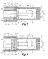
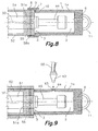
- FIG. 7 to 9 another example of embodiment of the device of the invention is shown, applied to a printing cylinder in which such means to releasably fasten the external liner 52 or the intermediate liner 53 on the shaft 51 comprise extensible elements associated to the shaft 51 mechanically or hydraulically driven, for example, expansion hydraulic bushings 51a and in which such means 50, 55 to introduce the compressed air in the chamber 2 include at least part of such pneumatic means to facilitate that the external liner 52 slides on the intermediate liner 53, which are similar to those disclosed with relation to the example of embodiment of Fig. 4 to 6 for creating the second air bag.
- the mouth 3 of the chamber 2 could have a size sufficient to communicate through an end 57b of such air bag with the interior of the chamber 2 to receive the compressed air from it (not shown).
- valve members 62 are shown which can be changed from and to a first and a second positions to selectively direct the compressed air to the deformable layer 59 through passageways 58a or to the chamber 2 through shifts 61a, respectively.
- the operation is analogous to the disclosed above with relation to the Fig. 5 and 6 and same tool can be used for changing from and to the first and second positions.
- Fig. 8 a variation is shown in which the surface 54b of the end of such intermediate liner 53 is a end portion of a cylindric external surface, coaxial to the shaft 51 centerline where outlets from the second passageways 58a are open while the surface 4b, which is arranged around the mouth 3, is an internal surface facing such surface 54b, being formed between both surfaces 4b, 54b, in lack of the external liner, a space 9 closed at its external end by sealing means 8, such as a O ring and communicated by its internal end with the chamber 2, for example, through channels or offsets 7 formed on an annular protuberance 10 of the internal wall of the chamber 2 which is abutting against a final flat surface of the intermediate liner 52 for communicating such space 9 with the chamber 2. Locking means are arranged 5 in this annular protuberance and flat final surface. The external liner would have previously removed by means of a body 1 similar to the shown in Fig. 5 .
- Fig. 9 shows another example of embodiment applied to a cylinder with expansion hydraulic bushings, although it could also be applied to any kind of cylinder with liners because, in it, the means for introducing compressed air in the chamber 2 are independent of the pneumatic means to facilitate that the liners slide.
- the body 1 is analogous to the one disclosed with respect to any of the Fig. 1 to 7 , and although it shows it connected to the intermediate liner 53, although it could be fastened to the external liner 52, but they comprise an inlet 65 to the chamber 2 which can communicate with a duct 60 connected to a compressed air supply.
- the said inlet 65 comprises a retaining valve 64 and such duct 60 is ending in a nozzle 63 which can be releasably coupled to the inlet 65 and it can be associated to handles provided with a catch for regulating the compressed air passageway, for example, a gun like (not shown).
- a quick connector for example, a gun like
- such body 1 is mounted at the end of a handling arm (not shown), for example, of the robotic kind, capable to automatically fasten/release it to/from such liner and to control the air exhaust to carry out the removal operation.
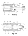
- Fig. 10 and 11 in which another example of embodiment is shown in which such wall 1a delimiting the chamber 2 is integral with an end of the external liner 52 instead of forming a detachable body 1, as above disclosed.
- the said wall 1a comprises a hole 67 through which a final configuration 66 of the shaft 51 is passing provided for supporting and guiding it.
- this configuration 66 requires a final stop 69
- such final stop 69 can be dismountable, for example, by means of a screw device 70.
- dynamic sealing means 68 are arranged, such as an O ring and the like, which prevent that the compressed air exhausts from the chamber while it allows that the wall 1a slides along the configuration 66.
- the means 50 for introducing compressed air in the chamber 2 use, as disclosed with relation to Fig. 1 to 3 , the said pneumatic means for facilitating that the liner 52 slides on the shaft 51.
- Fig. 10 shows the device idle, suitable for the rollers carrying out their functions, for example, in a printing machine, while in the Fig. 11 the device is shown operating, in which the compressed air within the chamber 2 generates extraction strengths, stated by the solid arrows, which makes the liner 52 slides joined to the wall 1a with respect to the shaft 51 in the direction stated by hollow arrows.
- the extraction strength will stop when the wall 1a arrives to the end of the configuration 66 and the compressed air exhausts through the hole 67, but an inertia will be created which, combined with the lower coefficient of dynamic friction, will be sufficient to allow that the liner is finished to be removed by hand.
Landscapes
- Actuator (AREA)
- Folding Of Thin Sheet-Like Materials, Special Discharging Devices, And Others (AREA)
- Supply, Installation And Extraction Of Printed Sheets Or Plates (AREA)
Claims (26)
- Vorrichtung zum Ausbau von Druckwalzenmanschetten, wobei die Druckwalzen eine Welle (51) aufweisen, die als Hülse wirkt, an der eine Druckmanschette befestigt wird, wobei Mittel zur ablösbaren Befestigung der Manschette an der Welle (51) sowie Pneumatikmittel zur leichteren Gleitbewegung der Manschette entlang der Welle (51) vorgesehen sind, dadurch gekennzeichnet, dass sie eine Kammer (2) aufweist, die von einer Wand (1a) begrenzt ist, die an einem Endstück der Manschette befestigt ist oder einen Teil davon bildet, sowie von zur Welle (51) gehörenden Flächen begrenzt ist, wobei Mittel (50, 60) zur Einleitung von Druckluft in die Kammer (2) vorgesehen sind, wobei die relative Anordnung einer Innenfläche der Wand (1a) und der zur Welle (51) gehörenden Flächen derart erfolgt, dass durch den auf die Flächen treffenden Druck axiale Komponenten einer Ausziehkraft erzeugt werden, die an der Welle und der Wand (1a), die an der Manschette befestigt sind bzw. einen Teil derselben bilden, in entgegengesetzter Richtung wirken, wobei die axialen Komponenten der Ausziehkraft in der Lage sind, die Gleitbewegung der Manschette entlang der Welle (51) zu bewirken.
- Vorrichtung nach Anspruch 1, dadurch gekennzeichnet, dass die die Kammer (2) begrenzende Wand (1a) einen Körper (1) bildet, in dem die Kammer (2) durch eine Mündung (3) geöffnet ist, die von einer Fläche (4, 4a, 4b) umgeben ist, wobei der Körper (1) an der Manschette mit einer lösbaren Verriegelungsvorrichtung (5) befestigt werden kann, wobei die Fläche (4, 4a, 4b) im wesentlichen dicht mit einer Fläche (54, 54a, 54b) des Manschettenendes gekoppelt ist und innerhalb des Umfangs der Mündung (3) ein Ende der Welle (51) einschließt.
- Vorrichtung nach Anspruch 2, dadurch gekennzeichnet, dass es sich bei der Manschette um eine Außenmanschette (52) bzw. eine Zwischenmanschette (53) handelt, an der die Außenmanschette (52) befestigt ist, wobei der Körper (1) an der Außenmanschette (52) bzw. der Zwischenmanschette (53) befestigt werden kann, wobei die Fläche (4, 4a, 4b) im wesentlichen dicht mit einer Fläche (54, 54a, 54b) des Endes derselben gekoppelt ist.
- Vorrichtung nach Anspruch 3, dadurch gekennzeichnet, dass die Mittel (50, 60) zur Einleitung von Druckluft in die Kammer (2) zumindest teilweise Pneumatikmittel zur leichteren Gleitbewegung der Außenmanschette (52) bzw. Zwischenmanschette (53) entlang der Welle (51) aufweisen, die einen Kanal (50) innerhalb der Welle (51) entlang derselben aufweisen und mit einer Druckluftversorgung sowie ersten Durchgängen (55) innerhalb der Welle (51) verbunden sind, die den Längskanal (50) mit einer ersten deformierbaren Schicht (56) aus einem zusammendrückbaren Material verbinden, die zwischen der Außenmanschette (52) bzw. Zwischenmanschette (53) und der Welle (51) angeordnet ist, wobei unterhalb der deformierbaren Schicht (56) ein erstes Luftkissen erzeugt werden kann.
- Vorrichtung nach Anspruch 4, dadurch gekennzeichnet, dass die Mündung (3) so groß ist, dass durch diese hindurch ein Ende (57) des ersten Luftkissens mit dem Innern der Kammer (2) kommunizieren kann.
- Vorrichtung nach Anspruch 4, dadurch gekennzeichnet, dass die Pneumatikmittel zweite Durchgänge (58) durch die Zwischenmanschette (53) hindurch aufweisen, durch die die ersten Durchgänge (55) zumindest teilweise mit einer zweiten deformierbaren Schicht (59) aus einem zusammendrückbaren Material kommunizieren, die zwischen der Außenmanschette (52) und der Zwischenmanschette (53) angeordnet ist, wobei unterhalb der zweiten deformierbaren Schicht (59) ein zweites Luftkissen erzeugt werden kann.
- Vorrichtung nach Anspruch 6, dadurch gekennzeichnet, dass die Mündung (3) so groß ist, dass durch diese hindurch ein Ende (57a) des zweiten Luftkissens mit dem Innern der Kammer (2) kommunizieren kann.
- Vorrichtung nach Anspruch 6, dadurch gekennzeichnet, dass sie mindestens eine Abzweigung (61) aufweist, über die zumindest einer der zweiten Durchgänge (58) mit einem Bereich der zweiten Fläche (54) des Endes der Zwischenmanschette (53) kommuniziert, die innerhalb des Umfangs der Mündung (3) der Kammer (2) liegt, wobei ein Ventilglied (62) an der Kreuzung des zweiten Durchgangs (58) mit der Abzweigung (61) angeordnet ist, die zwischen einer ersten Position, bei der die vom Längskanal (50) kommende Druckluft in Richtung der zweiten deformierbaren Schicht (59) durch den zweiten Durchgang (58) geleitet wird, und einer zweiten Position umschaltbar ist, bei der die vom Längskanal (50) kommende Druckluft in Richtung der Kammer (2) durch die Abzweigung (61) geleitet wird.
- Vorrichtung nach Anspruch 3, dadurch gekennzeichnet, dass die Mittel zur ablösbaren Befestigung der Außenmanschette (52) bzw. Zwischenmanschette (53) an der Welle (51) mit der Welle (51) verbundene mechanisch oder hydraulisch angetriebene ausdehnbare Elemente aufweisen und die Mittel (50, 60) zur Einleitung von Druckluft in die Kammer (2) zumindest teilweise Pneumatikmittel zur leichteren Gleitbewegung der Außenmanschette (52) entlang der Zwischenmanschette (53) aufweisen, die einen Kanal (50) innerhalb der Welle (51) entlang derselben aufweisen und mit einer Druckluftversorgung sowie ersten Durchgängen (55) innerhalb der Welle (51) verbunden sind, die den Längskanal (50) mit zweiten Durchgängen (58a) durch die Zwischenmanschette (53) verbinden, wobei die ersten Durchgänge (55) zumindest teilweise mit einer deformierbaren Schicht (59) aus einem zusammendrückbarem Material kommunizieren, die zwischen der Außenmanschette (52) und der Zwischenmanschette (53) angeordnet ist, wobei unterhalb der deformierbaren Schicht (59) ein Luftkissen erzeugt werden kann.
- Vorrichtung nach Anspruch 9, dadurch gekennzeichnet, dass die Mündung (3) so groß ist, dass durch diese hindurch ein Ende (57a) des Luftkissens mit dem Innern der Kammer (2) kommunizieren kann.
- Vorrichtung nach Anspruch 9, dadurch gekennzeichnet, dass sie mindestens eine Abzweigung (61) aufweist, über die zumindest einer der zweiten Durchgänge (58a) mit einem Bereich der zweiten Fläche (54a) des Endes der Zwischenmanschette (53) kommuniziert, die innerhalb des Umfangs der Mündung (3) der Kammer (2) liegt, wobei ein Ventilglied (62) an der Kreuzung des zweiten Durchgangs (58a) mit der Abzweigung (61) angeordnet ist, die zwischen einer ersten Position, bei der die vom Längskanal (50) kommende Druckluft in Richtung der zweiten deformierbaren Schicht (59) durch den zweiten Durchgang (58a) geleitet wird, und einer zweiten Position umschaltbar ist, bei der die vom Längskanal (50) kommende Druckluft in Richtung der Kammer (2) durch die Abzweigung (61) geleitet wird.
- Vorrichtung nach Anspruch 8 oder 11, dadurch gekennzeichnet, dass ein Werkzeug zur Durchführung dieser Positionsumschaltung des Ventilglieds (62) vorgesehen ist, das über die entsprechende Abzweigung (61) von deren Öffnung in der Fläche (54, 54a) des Endes der Zwischenmanschette (53) zugänglich ist.
- Vorrichtung nach Anspruch 9, dadurch gekennzeichnet, dass die Fläche (54b) des Endes der Zwischenmanschette (53) ein Endabschnitt einer Zylinderaußenfläche ist, die koaxial zur Mittellinie der Welle (51) verläuft, bei der die Ausgänge der zweiten Durchgänge (58a) offen sind und die Fläche (4b), die um die Mündung (3) herum angeordnet ist, eine der Fläche (54b) gegenüberliegende Innenfläche ist, wobei zwischen beiden Flächen (4b, 54b) bei Fehlen der Außenmanschette ein Raum (9) gebildet wird, der an seinem äußeren Ende mit Dichtmitteln (8) verschlossen ist und an seinem inneren Ende mit der Kammer (2) kommuniziert.
- Vorrichtung nach Anspruch 13, dadurch gekennzeichnet, dass sie Kanäle oder Versätze (7) aufweist, die in einem ringförmigen Vorsprung (10) des Körpers (1) angeordnet sind, die an einer Endplanfläche der Zwischenmanschette (53) anliegt, um den Raum (9) mit der Kammer (2) zu verbinden.
- Vorrichtung nach Anspruch 3, dadurch gekennzeichnet, dass die Mittel (60, 65) zur Einleitung von Druckluft in die Kammer (2) einen Einlass (65) zur Kammer (2) im Körper (1) aufweisen, der mit einem mit der Druckluftversorgung verbundenen Kanal (60) kommunizieren kann.
- Vorrichtung nach Anspruch 15, dadurch gekennzeichnet, dass der Einlass (65) ein Sicherheitsventil (64) aufweist, wobei der Kanal (60) in einer Düse (63) endet, die mit dem Einlass (65) lösbar gekoppelt werden kann.
- Vorrichtung nach Anspruch 16, dadurch gekennzeichnet, dass die Düse mit einem Griff verbunden ist, der mit einer Sperre zur Regulierung des Druckluftstroms versehen ist.
- Vorrichtung nach Anspruch 17, dadurch gekennzeichnet, dass sie eine Schnellsteckverbindung zur Verbindung/Lösung des Einlasses (65) mit/vom Kanal (60) aufweist.
- Vorrichtung nach einem der Ansprüche 1 bis 12, dadurch gekennzeichnet, dass die Fläche (54) des Endes der Außenmanschette (52) bzw. Zwischenmanschette (53) eine ringförmige Planfläche ist, die im wesentlichen senkrecht zur Mittellinie der Welle (51) angeordnet ist, und die Fläche (4), die um die Mündung (3) herum angeordnet ist, eine entsprechende ringförmige Planfläche ist.
- Vorrichtung nach einem der vorhergehenden Ansprüche, dadurch gekennzeichnet, dass die lösbare Verriegelungsvorrichtung (5) zwischen dem Körper (1) und der Außenmanschette (52) bzw. Zwischenmanschette (53) einen Bajonettverschluss aufweist.
- Vorrichtung nach einem der vorhergehenden Ansprüche, dadurch gekennzeichnet, dass in der Kammer (2) des Körpers (1) im Betrieb eine Endkonfiguration (66) der Welle (51) untergebracht werden kann, die zu dessen Stützung und Führung dient.
- Vorrichtung nach einem der vorhergehenden Ansprüche, dadurch gekennzeichnet, dass der Körper (1) zumindest eine Ausblasöffnung (6) aufweist, die die Kammer (2) mit der Außenumgebung verbindet, wobei der Durchgang der Ausblasöffnung (6) reguliert werden kann, um damit die Ausbaustärke zu regulieren.
- Vorrichtung nach Anspruch 22, dadurch gekennzeichnet, dass sich die Ausblasöffnung (6) nahe eines Griffs (11) befindet, der an dem Körper (1) befestigt ist, wobei der Durchgang der Ausblasöffnung (6) handreguliert werden kann, indem man den Griff (11) mit einem Finger einer Hand berührt und ihn festhält.
- Vorrichtung nach Anspruch 3, dadurch gekennzeichnet, dass es sich bei der Außenmanschette (52) um eine Klischeehaltermanschette oder eine Sieb- oder Farbauftragsmanschette handelt.
- Vorrichtung nach Anspruch 3, dadurch gekennzeichnet, dass der Körper (1) am Ende eines Bedienungsarms befestigt ist, der zwecks Durchführung des Ausbauvorgangs zur automatischen Befestigung bzw. zum Lösen der Manschette befähigt ist.
- Vorrichtung nach Anspruch 1, dadurch gekennzeichnet, dass die die Kammer (2) begrenzende Wand (1a) mit einem Ende der Manschette integral verbunden ist und ein Loch (67) aufweist, durch das eine Endkonfiguration (66) der Welle (51) geführt wird, die zu deren Stützung und Führung dient, wobei zwischen dem Loch (67) und der Endkonfiguration (66) dynamische Dichtmittel (68) vorgesehen sind, wobei die Mittel (50) zur Einleitung von Druckluft in die Kammer (2) zumindest teilweise Pneumatikmittel zur leichteren Gleitbewegung der Manschette entlang der Welle (51) aufweisen.
Applications Claiming Priority (1)
| Application Number | Priority Date | Filing Date | Title |
|---|---|---|---|
| PCT/ES2002/000220 WO2003095207A1 (es) | 2002-05-10 | 2002-05-10 | Dispositivo extractor de camisas de cilindros de impresion |
Publications (2)
| Publication Number | Publication Date |
|---|---|
| EP1504899A1 EP1504899A1 (de) | 2005-02-09 |
| EP1504899B1 true EP1504899B1 (de) | 2008-02-13 |
Family
ID=29414902
Family Applications (1)
| Application Number | Title | Priority Date | Filing Date |
|---|---|---|---|
| EP02730313A Expired - Lifetime EP1504899B1 (de) | 2002-05-10 | 2002-05-10 | Vorrichtung zum entfernen von druckzylinderhülsen |
Country Status (7)
| Country | Link |
|---|---|
| EP (1) | EP1504899B1 (de) |
| AR (1) | AR039992A1 (de) |
| AT (1) | ATE385895T1 (de) |
| AU (1) | AU2002302659A1 (de) |
| DE (1) | DE60225076D1 (de) |
| ES (1) | ES2301641T3 (de) |
| WO (1) | WO2003095207A1 (de) |
Families Citing this family (2)
| Publication number | Priority date | Publication date | Assignee | Title |
|---|---|---|---|---|
| ES2242520B1 (es) | 2004-01-14 | 2007-02-16 | Comexi, S.A. | Dispositivo automatico de manipulacion y transporte de camisas de impresion. |
| EP3792061A1 (de) * | 2019-09-11 | 2021-03-17 | Flint Group Germany GmbH | Verfahren zur montage bzw. demontage eines holzylinders auf bzw. aus einem weiteren zylinder und montagehilfe |
Family Cites Families (6)
| Publication number | Priority date | Publication date | Assignee | Title |
|---|---|---|---|---|
| US4903597A (en) * | 1988-10-24 | 1990-02-27 | Lavalley Industries, Inc. | Printing sleeves and methods for mounting and dismounting |
| US5481975A (en) * | 1994-10-03 | 1996-01-09 | Schulz; Werner | Printing cylinder mandrel and image carrier sleeve |
| FR2726786A1 (fr) * | 1994-11-14 | 1996-05-15 | Francille Jean | Agencement et manchon intercalaire porte-manchon mince notamment pour machine d'impression flexographique |
| US5840386A (en) * | 1996-02-22 | 1998-11-24 | Praxair S.T. Technology, Inc. | Sleeve for a liquid transfer roll and method for producing it |
| US5819657A (en) * | 1996-03-11 | 1998-10-13 | Ermino Rossini, Spa | Air carrier spacer sleeve for a printing cylinder |
| US5904095A (en) * | 1997-03-19 | 1999-05-18 | Meca Of Green Bay, Inc. | Bridge mandrel for flexographic printing presses |
-
2002
- 2002-05-10 AU AU2002302659A patent/AU2002302659A1/en not_active Abandoned
- 2002-05-10 EP EP02730313A patent/EP1504899B1/de not_active Expired - Lifetime
- 2002-05-10 ES ES02730313T patent/ES2301641T3/es not_active Expired - Lifetime
- 2002-05-10 WO PCT/ES2002/000220 patent/WO2003095207A1/es not_active Ceased
- 2002-05-10 DE DE60225076T patent/DE60225076D1/de not_active Expired - Lifetime
- 2002-05-10 AT AT02730313T patent/ATE385895T1/de not_active IP Right Cessation
-
2003
- 2003-05-09 AR ARP030101628A patent/AR039992A1/es unknown
Also Published As
| Publication number | Publication date |
|---|---|
| EP1504899A1 (de) | 2005-02-09 |
| ES2301641T3 (es) | 2008-07-01 |
| WO2003095207A1 (es) | 2003-11-20 |
| DE60225076D1 (de) | 2008-03-27 |
| AU2002302659A1 (en) | 2003-11-11 |
| ATE385895T1 (de) | 2008-03-15 |
| AR039992A1 (es) | 2005-03-09 |
Similar Documents
| Publication | Publication Date | Title |
|---|---|---|
| KR100381114B1 (ko) | 회전 압연기 내에서 롤 네크 상의 착좌위치 및 그 외부로 베어링 조립체를 축방향 가압하기 위한 장치 | |
| US7059030B2 (en) | Pressing device | |
| JPH0255136B2 (de) | ||
| JP2004502099A (ja) | 軸方向ロッキング装置を有する複動式油圧シリンダ | |
| EP1504899A1 (de) | Vorrichtung zum entfernen von druckzylinderhülsen | |
| CZ135197A3 (en) | Device with air-operated working cylinder | |
| JPH0571356B2 (de) | ||
| SE469953B (sv) | Rörkoppling med svängklaff | |
| EP1104507B1 (de) | Hydraulische zylinder | |
| IT202000019792A1 (it) | Kit di installazione per un espulsore pneumatico lineare del tipo collegabile ad un braccio di uno svolgitore a bracci mobili | |
| JPH0775906A (ja) | 自動工具交換装置 | |
| EP1679189B1 (de) | Verbundwelle für druckzylinder mit hydraulischer hülsenbefestigungsvorrichtung | |
| JP2972743B1 (ja) | ナット締結装置および締結方法 | |
| JPH0478435B2 (de) | ||
| JPH05203078A (ja) | スプール弁本体 | |
| EP1077096B1 (de) | Vorrichtung zum Setzen von zweiteiligen Befestigungselementen | |
| GB2137140A (en) | Printing Cylinders | |
| CN110947812A (zh) | 缸装置及其工作方法、冲压装置、工件夹持装置、工件的冲压方法及夹持方法 | |
| EP0818380A3 (de) | Servolenkung mit leicht einstellbarem Gegenkraftmechanismus | |
| WO2004018210A1 (en) | Device and method for mounting/demounting sleeves on/from a printing cylinder, particularly for a rotary printing press | |
| CA1113228A (en) | Portable hydraulic gear pulling device | |
| JP2010221324A (ja) | ピストンアセンブリ組み付け治具およびピストンアセンブリ組み付け方法 | |
| JPS5936777Y2 (ja) | 回転する操作用シリンダへの圧力媒体供給装置 | |
| JP2920020B2 (ja) | シリンダーのロック機構 | |
| JP3051044B2 (ja) | ロール幅調整装置 |
Legal Events
| Date | Code | Title | Description |
|---|---|---|---|
| PUAI | Public reference made under article 153(3) epc to a published international application that has entered the european phase |
Free format text: ORIGINAL CODE: 0009012 |
|
| 17P | Request for examination filed |
Effective date: 20041124 |
|
| AK | Designated contracting states |
Kind code of ref document: A1 Designated state(s): AT BE CH CY DE DK ES FI FR GB GR IE IT LI LU MC NL PT SE TR |
|
| AX | Request for extension of the european patent |
Extension state: AL LT LV MK RO SI |
|
| DAX | Request for extension of the european patent (deleted) | ||
| 17Q | First examination report despatched |
Effective date: 20070222 |
|
| GRAP | Despatch of communication of intention to grant a patent |
Free format text: ORIGINAL CODE: EPIDOSNIGR1 |
|
| GRAS | Grant fee paid |
Free format text: ORIGINAL CODE: EPIDOSNIGR3 |
|
| GRAA | (expected) grant |
Free format text: ORIGINAL CODE: 0009210 |
|
| AK | Designated contracting states |
Kind code of ref document: B1 Designated state(s): AT BE CH CY DE DK ES FI FR GB GR IE IT LI LU MC NL PT SE TR |
|
| REG | Reference to a national code |
Ref country code: GB Ref legal event code: FG4D |
|
| RIN1 | Information on inventor provided before grant (corrected) |
Inventor name: VINAS I TURRO, MIQUEL |
|
| REG | Reference to a national code |
Ref country code: CH Ref legal event code: EP |
|
| REG | Reference to a national code |
Ref country code: IE Ref legal event code: FG4D |
|
| REF | Corresponds to: |
Ref document number: 60225076 Country of ref document: DE Date of ref document: 20080327 Kind code of ref document: P |
|
| REG | Reference to a national code |
Ref country code: ES Ref legal event code: FG2A Ref document number: 2301641 Country of ref document: ES Kind code of ref document: T3 |
|
| PG25 | Lapsed in a contracting state [announced via postgrant information from national office to epo] |
Ref country code: FI Free format text: LAPSE BECAUSE OF FAILURE TO SUBMIT A TRANSLATION OF THE DESCRIPTION OR TO PAY THE FEE WITHIN THE PRESCRIBED TIME-LIMIT Effective date: 20080213 |
|
| PGFP | Annual fee paid to national office [announced via postgrant information from national office to epo] |
Ref country code: ES Payment date: 20080516 Year of fee payment: 7 |
|
| NLV1 | Nl: lapsed or annulled due to failure to fulfill the requirements of art. 29p and 29m of the patents act | ||
| PG25 | Lapsed in a contracting state [announced via postgrant information from national office to epo] |
Ref country code: AT Free format text: LAPSE BECAUSE OF FAILURE TO SUBMIT A TRANSLATION OF THE DESCRIPTION OR TO PAY THE FEE WITHIN THE PRESCRIBED TIME-LIMIT Effective date: 20080213 |
|
| PG25 | Lapsed in a contracting state [announced via postgrant information from national office to epo] |
Ref country code: BE Free format text: LAPSE BECAUSE OF FAILURE TO SUBMIT A TRANSLATION OF THE DESCRIPTION OR TO PAY THE FEE WITHIN THE PRESCRIBED TIME-LIMIT Effective date: 20080213 |
|
| PG25 | Lapsed in a contracting state [announced via postgrant information from national office to epo] |
Ref country code: PT Free format text: LAPSE BECAUSE OF FAILURE TO SUBMIT A TRANSLATION OF THE DESCRIPTION OR TO PAY THE FEE WITHIN THE PRESCRIBED TIME-LIMIT Effective date: 20080714 Ref country code: DK Free format text: LAPSE BECAUSE OF FAILURE TO SUBMIT A TRANSLATION OF THE DESCRIPTION OR TO PAY THE FEE WITHIN THE PRESCRIBED TIME-LIMIT Effective date: 20080213 Ref country code: NL Free format text: LAPSE BECAUSE OF FAILURE TO SUBMIT A TRANSLATION OF THE DESCRIPTION OR TO PAY THE FEE WITHIN THE PRESCRIBED TIME-LIMIT Effective date: 20080213 Ref country code: SE Free format text: LAPSE BECAUSE OF FAILURE TO SUBMIT A TRANSLATION OF THE DESCRIPTION OR TO PAY THE FEE WITHIN THE PRESCRIBED TIME-LIMIT Effective date: 20080513 |
|
| EN | Fr: translation not filed | ||
| PLBE | No opposition filed within time limit |
Free format text: ORIGINAL CODE: 0009261 |
|
| STAA | Information on the status of an ep patent application or granted ep patent |
Free format text: STATUS: NO OPPOSITION FILED WITHIN TIME LIMIT |
|
| PG25 | Lapsed in a contracting state [announced via postgrant information from national office to epo] |
Ref country code: MC Free format text: LAPSE BECAUSE OF NON-PAYMENT OF DUE FEES Effective date: 20080531 |
|
| REG | Reference to a national code |
Ref country code: CH Ref legal event code: PL |
|
| 26N | No opposition filed |
Effective date: 20081114 |
|
| GBPC | Gb: european patent ceased through non-payment of renewal fee |
Effective date: 20080513 |
|
| PG25 | Lapsed in a contracting state [announced via postgrant information from national office to epo] |
Ref country code: CH Free format text: LAPSE BECAUSE OF NON-PAYMENT OF DUE FEES Effective date: 20080531 Ref country code: LI Free format text: LAPSE BECAUSE OF NON-PAYMENT OF DUE FEES Effective date: 20080531 Ref country code: DE Free format text: LAPSE BECAUSE OF FAILURE TO SUBMIT A TRANSLATION OF THE DESCRIPTION OR TO PAY THE FEE WITHIN THE PRESCRIBED TIME-LIMIT Effective date: 20080514 |
|
| PG25 | Lapsed in a contracting state [announced via postgrant information from national office to epo] |
Ref country code: FR Free format text: LAPSE BECAUSE OF FAILURE TO SUBMIT A TRANSLATION OF THE DESCRIPTION OR TO PAY THE FEE WITHIN THE PRESCRIBED TIME-LIMIT Effective date: 20081205 Ref country code: IE Free format text: LAPSE BECAUSE OF NON-PAYMENT OF DUE FEES Effective date: 20080512 |
|
| PG25 | Lapsed in a contracting state [announced via postgrant information from national office to epo] |
Ref country code: GB Free format text: LAPSE BECAUSE OF NON-PAYMENT OF DUE FEES Effective date: 20080513 |
|
| PG25 | Lapsed in a contracting state [announced via postgrant information from national office to epo] |
Ref country code: CY Free format text: LAPSE BECAUSE OF FAILURE TO SUBMIT A TRANSLATION OF THE DESCRIPTION OR TO PAY THE FEE WITHIN THE PRESCRIBED TIME-LIMIT Effective date: 20080213 |
|
| PG25 | Lapsed in a contracting state [announced via postgrant information from national office to epo] |
Ref country code: IT Free format text: LAPSE BECAUSE OF FAILURE TO SUBMIT A TRANSLATION OF THE DESCRIPTION OR TO PAY THE FEE WITHIN THE PRESCRIBED TIME-LIMIT Effective date: 20080213 |
|
| REG | Reference to a national code |
Ref country code: ES Ref legal event code: FD2A Effective date: 20090511 |
|
| PG25 | Lapsed in a contracting state [announced via postgrant information from national office to epo] |
Ref country code: LU Free format text: LAPSE BECAUSE OF NON-PAYMENT OF DUE FEES Effective date: 20080510 |
|
| PG25 | Lapsed in a contracting state [announced via postgrant information from national office to epo] |
Ref country code: TR Free format text: LAPSE BECAUSE OF FAILURE TO SUBMIT A TRANSLATION OF THE DESCRIPTION OR TO PAY THE FEE WITHIN THE PRESCRIBED TIME-LIMIT Effective date: 20080213 |
|
| PG25 | Lapsed in a contracting state [announced via postgrant information from national office to epo] |
Ref country code: ES Free format text: LAPSE BECAUSE OF NON-PAYMENT OF DUE FEES Effective date: 20090511 Ref country code: GR Free format text: LAPSE BECAUSE OF FAILURE TO SUBMIT A TRANSLATION OF THE DESCRIPTION OR TO PAY THE FEE WITHIN THE PRESCRIBED TIME-LIMIT Effective date: 20080514 |