EP1505590B1 - Kombiniertes Bandabspielgerät und Lesegerät für optische Datenträger - Google Patents
Kombiniertes Bandabspielgerät und Lesegerät für optische Datenträger Download PDFInfo
- Publication number
- EP1505590B1 EP1505590B1 EP04103343A EP04103343A EP1505590B1 EP 1505590 B1 EP1505590 B1 EP 1505590B1 EP 04103343 A EP04103343 A EP 04103343A EP 04103343 A EP04103343 A EP 04103343A EP 1505590 B1 EP1505590 B1 EP 1505590B1
- Authority
- EP
- European Patent Office
- Prior art keywords
- vcr
- unit
- control data
- dvdp
- optical media
- Prior art date
- Legal status (The legal status is an assumption and is not a legal conclusion. Google has not performed a legal analysis and makes no representation as to the accuracy of the status listed.)
- Expired - Lifetime
Links
Images


Classifications
-
- G—PHYSICS
- G11—INFORMATION STORAGE
- G11B—INFORMATION STORAGE BASED ON RELATIVE MOVEMENT BETWEEN RECORD CARRIER AND TRANSDUCER
- G11B20/00—Signal processing not specific to the method of recording or reproducing; Circuits therefor
- G11B20/10—Digital recording or reproducing
-
- G—PHYSICS
- G11—INFORMATION STORAGE
- G11B—INFORMATION STORAGE BASED ON RELATIVE MOVEMENT BETWEEN RECORD CARRIER AND TRANSDUCER
- G11B20/00—Signal processing not specific to the method of recording or reproducing; Circuits therefor
- G11B20/10—Digital recording or reproducing
- G11B20/18—Error detection or correction; Testing, e.g. of drop-outs
-
- G—PHYSICS
- G11—INFORMATION STORAGE
- G11B—INFORMATION STORAGE BASED ON RELATIVE MOVEMENT BETWEEN RECORD CARRIER AND TRANSDUCER
- G11B31/00—Arrangements for the associated working of recording or reproducing apparatus with related apparatus
- G11B31/006—Arrangements for the associated working of recording or reproducing apparatus with related apparatus with video camera or receiver
Definitions
- the present invention relates to a combined video tape and optical media apparatus comprising a video tape player and an optical media reader, the apparatus comprising control means having a processor and storage means operable to store control data arranged to control the video tape player.
- CPU Central Processing Unit
- RAM Random Access Memory
- ROM Read Only Memory
- A/D an analogue-to-digital converter
- the one-chip design is useful because it can simplify the addition of peripheral components.
- the one-chip design offers improved performance compared to a circuit having separate components, and thus has been used as an essential core component to many applications.
- An electronic appliance using a one-chip may be, for example, a microwave oven, a Video Tape Recorder (VTR), and a Digital Video Disc Player/Video Cassette Recorder (DVDP/VCR) combination system.
- VTR Video Tape Recorder
- DVDP/VCR Digital Video Disc Player/Video Cassette Recorder
- FIG. 1 is a block diagram illustrating an example of a conventional DVDP/VCR combination system.
- the DVDP/VCR combination system 100 includes a VCR unit 110 for performing a general function of a VCR, a DVDP unit 120 for performing a general function of a DVDP, a selection unit 130 for selecting between the signals output from the VCR unit 110 and the DVDP unit 120, an input unit 140 for providing signals from external appliances such as a camcorder to the selection unit 130, an output unit 150 for providing the signals output from the VCR unit 110 and the DVDP unit 120 to peripheral appliances such as a television receiver (TV), an amplifier, etc., and an On-Screen Display (OSD) block 160 for adding an OSD function to video signals output from the VCR unit 110 and the DVDP unit 120.
- VCR unit 110 for performing a general function of a VCR
- DVDP unit 120 for performing a general function of a DVDP
- a selection unit 130 for selecting between the signals output from the VCR unit 110 and the DVDP unit 120
- the VCR unit 110 includes a VCR deck 111 for recording a signal on a magnetic tape or reproducing a signal recorded on the magnetic tape, a video block 112 and an audio block 113 for processing video and audio signals to be recorded and reproduced using the VCR deck 111, and a VCR one-chip 114 for controlling the VCR deck 111, the video block 112 and the audio block 113.
- the VCR one-chip 114 includes a VCR driving information storage unit 114a for storing information for controlling constituent elements of the VCR unit 110, i.e., a program for controlling the VCR unit 110, and a VCR control unit 114b for controlling the components of the VCR unit 110 using the control information stored in the VCR driving information storage unit 114a.
- the VCR unit 110 is provided with a display 116 for displaying status information of the VCR unit 110 such as operation, control, mode, etc., to allow a user to recognise the status information of the VCR unit, a manipulation panel 117 for receiving various commands from the user, and a remote control sensor 118 for receiving various commands from the user through a remote controller 180.
- a display 116 for displaying status information of the VCR unit 110 such as operation, control, mode, etc., to allow a user to recognise the status information of the VCR unit
- a manipulation panel 117 for receiving various commands from the user
- a remote control sensor 118 for receiving various commands from the user through a remote controller 180.
- the DVDP unit 120 includes a DVD deck 121, a DVD servo 122, a DVD one-chip 123, a Moving Picture Expert Group (MPEG) decoder 124, and a DVDP correction information storage unit 125. Also, the DVD one-chip 123 includes a DVDP control information storage unit 123a and a DVDP control unit 123b.
- MPEG Moving Picture Expert Group
- the DVD deck 121 reads data recorded on the DVD in order to reproduce picture information stored thereon, and the DVD servo 122 performs position and speed control of the DVD deck 121. Also, the DVD deck 121 reads DVDP correction information for compensating for DVDP information from a medium, for example a DVD.
- the DVDP correction information is useful if an error is found in the DVDP control information stored in the DVDP driving information storage unit 123a after the DVDP/VCR combination system is produced.
- the MPEG decoder 124 receives the data read by the DVD deck 121 through the DVD control unit 123, and outputs DVD video data and DVD sound data.
- the DVDP driving information storage unit 123a stores information for controlling the DVDP unit 120.
- the DVD control unit 123 reads the DVDP information stored in the DVDP driving information storage unit 123a, and controls the DVD deck 121, the DVD servo 122 and the MPEG decoder 124 of the DVDP unit 120 accordingly.
- the DVDP correction information storage unit 125 stores the DVDP correction information read by the DVD deck 121 if an error is present in the DVDP information stored in the DVDP driving information storage unit 123a.
- the DVDP correction information storage unit 125 is distinct from the DVDP driving information storage unit 123a provided inside the DVDP one-chip 123, and is installed separately from the DVDP one-chip 123.
- the DVDP correction information storage unit 125 is implemented using an Electrically Erasable and Programmable ROM (EEPROM) or a flash ROM which can erase the previously stored data and update new data.
- EEPROM Electrically Erasable and Programmable ROM
- the DVDP control unit 123b compensates for the damaged DVDP information by controlling the DVDP unit 120 in accordance with the DVDP correction information stored in the DVDP correction information storage unit 125.
- the selection unit 130 receives an output from the MPEG decoder 124, an output from both the video and audio blocks 112 and 113, and a signal from the input unit 140.
- the selection unit 130 selects between the VCR control unit 114 and the DVD control unit 123, and the output of the selection unit 130 is input to the OSD block 160 and the output unit 150.
- the OSD block 160 serves to add the OSD functionality to the signal from the selection unit 130. Accordingly, a menu for controlling the DVDP unit 120 and the VCR unit 110 and an image, such as the menu, which is to be added to the image signal output to the TV screen are provided by the OSD block 160.
- the output unit 150 receives signals from the DVD encoder 124, the selection unit 130 and the OSD block 160, and outputs signals related to the DVD image, DVD sound, VCR image and VCR sound.
- the output unit 150 is connected to peripheral appliances such as a TV, audio appliance, etc., so that the images and the sounds are appropriately output through the peripheral appliances.
- the input unit 140 is connected to the selection unit 130, and serves to transfer the externally input signals (from camcorders and the like) to the selection unit 130. Accordingly, signals recorded on the external appliances can be transmitted to the combination system 100 through the input unit 140, and can also be recorded on the magnetic tape using the VCR unit 110 or reproduced through the TV.
- the DVDP information can be compensated for by reading the DVDP correction information from the DVD having the DVDP correction information recorded thereon, it is difficult to compensate for the VCR driving information by reading the VCR correction information from the VCR that is a magnetic recording medium if an error is found in the VCR driving information in the VCR one-chip 114.
- the DVDP/VCR combination system needs to be opened, respective parts disassembled, and the VCR one-chip be replaced. This is inconvenient and expensive.
- the one-chip itself should be replaced. This results in a loss in time and an increase in cost to replace the one-chip.
- JP-A-58106975 describes an apparatus having the pre-characterising parts of claim 1 appended hereto.
- the present invention relates to a combined video tape and optical media apparatus comprising a video tape player and an optical media reader, the apparatus comprising control means having a processor and storage means operable to store control data arranged to control the video tape player.
- a method according to the present invention is provided in claim 10 appended hereto.
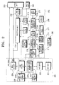
- the DVDP/VCR combination system includes a VCR unit 205 for performing the function of a VCR, a DVDP unit 220 for performing a general function of a DVDP, a selection unit 230 for selecting between the VCR unit 205 and the DVDP unit 220, an input unit 240 for providing signals input from external appliances such as a camcorder to the selection unit 230, an output unit 250 for providing the signals output from the VCR unit 205 and the DVDP unit 220 to peripheral appliances such as a TV, an amplifier, etc., and an On-Screen Display (OSD) block 260 for adding an OSD function to video signals output from the VCR unit 205 and the DVDP unit 220.
- OSD On-Screen Display
- the VCR unit 205 includes a switching signal input unit 210, a VCR deck unit 211, a video block 212, an audio block 213, a VCR one-chip 214, a VCR correction information storage unit 215, a display 216, a manipulation panel 217, a remote control sensor 218, and a switching selection setting unit 219.
- the VCR one-chip 214 includes a VCR driving information storage unit 214a, a VCR control unit 214b, and an address searching unit 214c.
- the DVDP unit 220 includes a DVD deck unit 221, a DVD servo 222, a DVD one-chip 223, a Moving Picture Expert Group (MPEG) decoder 224, and an area separation type storage unit 225.
- the DVDP one-chip 223 includes a DVDP driving information storage unit 223a and a DVDP control unit 223b.
- VCR deck unit 211 the construction and operation of the VCR deck unit 211, video block 212, audio block 213, manipulation panel 217, remote control sensor 218, selection unit 230, output unit 250, input unit, OSD block 260, DVD servo 222, and MPEG decoder 224 are the same as described above, and the explanation thereof will be omitted.
- the switching signal input unit 210 inputs a switching signal for switching the control of the VCR unit 205 from the information stored in the VCR driving information storage unit 214a over to the correction information stored in the VCR correction information storage unit 215.
- the VCR driving information storage unit 214a is provided inside the VCR one-chip 124, and stores the information for controlling the VCR unit 205.
- the VCR driving information storage unit 214a is provided with a predetermined area where correction is possible by a user of the DVDP/VCR combination system, and a specified address is given to the allocated area.
- the VCR control unit 214b controls the VCR unit 205 using the VCR correction information stored in the VCR correction information storage unit 215.
- the address searching unit 214c searches for a section of the VCR correction information that coincides with a section of the VCR driving information to be switched.
- the VCR correction information storage unit 215 stores the correction information for compensating for the VCR driving information. It is preferable that the VCR correction information storage unit 215 is separate to the VCR one-chip 214 and is distinct from the VCR driving information storage unit 214a provided inside the VCR one-chip 214. It is also preferable that the VCR correction information storage unit 215 is implemented using an Electrically Erasable and Programmable ROM (EEPROM) or a flash Read Only Memory (ROM) so that the existing stored data can be erased and new data can be uploaded.
- EEPROM Electrically Erasable and Programmable ROM
- ROM flash Read Only Memory
- the display 216 displays the VCR driving information stored in the VCR driving information storage unit 214a or the DVDP driving information stored in the DVDP driving information storage unit 223a.
- the displaying of the driving information may be performed during operation of the VCR unit 205 or the DVDP unit 220 or under the user's command.
- the user of the DVDP/VCR combination system can designate a section of the VCR driving information or the DVDP driving information to be displayed. Since the section of the VCR driving information or the DVDP driving information designated by the user refers to the section where the control of the VCR unit 205 switches from using VCR driving information to the VCR correction information this is called a 'switching section'.
- a similar analogy can be made for transfer of control for the DVDP unit 220. If an error occurs in the DVDP information, the same technology as that used in the conventional DVDP/VCR combination system is used, and thus the explanation thereof will be omitted while only the compensation of an improved VCR driving information will now be explained.
- the switching section setting unit 219 sets the switching section allowing the VCR unit 205 to be controlled by the VCR correction information rather than the VCR driving information.
- the switching section setting unit 219 sets the switching section by designating a start address and an end address of an area, which is to be corrected, of the VCR driving information displayed on the display 216.
- the user of the DVDP/VCR combination system may allocate the correction area instead of allowing the switching section setting unit 219 to automatically designate an address of an area of the VCR correction information corresponding to the correction area of the VCR driving information.
- the user of the DVDP/VCR combination system intends to compensate for the VCR driving information stored in the VCR driving information storage unit 214a or the DVDP driving information stored in the DVDP driving information storage unit 223a the user records the VCR correction information and/or DVDP correction information to be compensated for onto a DVD, and inserts the DVD in the DVD deck unit 221.
- the DVD deck unit 221 reads the DVDP driving information, the VCR correction information for compensating for the VCR driving information or the DVDP correction information from the DVD, and stores the readout correction information in the area separation type storage unit 225.
- the area separation type storage unit 225 is provided with a VCR correction information area for storing the VCR correction information and a DVDP correction information area for storing the DVDP correction information among the correction information read from the DVD. It is preferable that the area separation type storage unit 225 is installed separate from the DVDP one-chip 223 and is distinct from the DVDP driving information storage unit 223a provided inside the DVDP one-chip 223. It is also preferable that the area separation type storage unit 225 is implemented using an EEPROM or a flash ROM so that the existing stored data can be erased and new data can be uploaded. Hereinafter, the area separation type storage unit 225 is called a 'DVDP correction information storage unit' in order to distinguish it from the VCR correction information storage unit 214a of the VCR unit 205.
- the reset-sensing unit 226 detects the reset of the DVDP/VCR combination system. If the DVDP/VCR combination system is reset, the reset-sensing unit 226 informs the DVDP control unit 223b by transmitting a reset-sensing signal to the DVDP control unit 223b. If the reset-sensing signal is received from the reset-sensing unit 226, the DVDP control unit 223b transmits the VCR correction information stored in the VCR correction information area of the area separation type storage unit 225 to the VCR correction information storage unit 215, so that the VCR correction information stored in the VCR correction information storage unit 215 can be uploaded.
- the combination system according to the embodiment of the present invention is not limited to a DVDP/VCR combination system, but diverse types of combination systems can be implemented.
- the first appliance of the combination system may be a digital TV (DTV)
- the second appliance may be a VCR.
- the user of the DVDP/VCR combination system records the DVDP correction information or the VCR correction information to be compensated for onto a DVD, and inserts the DVD in the DVD deck unit 221.
- the DVD deck unit 221 reads the DVDP correction information and the VCR correction information from the inserted DVD (step S301).
- the DVDP control unit 223a separates and stores the readout DVDP correction information and the VCR correction information in the DVDP correction information area and the VCR correction information area provided in the area separation type storage unit 225, respectively (step S303).
- the reset-sensing unit 226 detects the reset of the DVDP/VCR combination system (step S305). If the reset of the DVDP/VCR combination system is detected through the reset-sensing unit 226, the DVDP control unit 223b receives the reset-sensing signal from the reset-sensing unit 226, and transmits the DVDP correction information stored in the area separation type storage unit 225 to the VCR correction information storage unit 215 in accordance with the received reset-sensing signal (step S307). As a result, whenever the DVDP/VCR combination system is reset, the DVDP control unit 223b searches whether the VCR correction information is stored in the area separation type storage unit 225, and transmits the searched VCR correction information to the VCR correction information storage unit 215.
- the VCR correction information storage unit 215 stores the received VCR correction information (step S309).
- the display 216 displays the VCR driving information stored in the VCR driving information storage unit 214a (step S311).
- the display of the VCR driving information through the display 216 may be performed during the operation of the VCR unit 205 by the VCR driving information or by a display command of the user of the DVDP/VCR combination system.
- the user of the DVDP/VCR combination system sets the switching section to the VCR driving information through the switching section setting unit 219 as the user is viewing the VCR driving information displayed on the display (step S313).
- the switching section of the VCR driving information is set through the designating of a start address and an end address of the area of the VCR driving information to be corrected.
- the user of the DVDP/VCR combination system inputs a switching signal for switching the operation of the VCR unit 205 using the VCR driving information stored in the VCR driving information storage unit 214a to operating the VCR unit 205 using the VCR correction information stored in the VCR correction information storage unit 215 through the switching signal input unit 210 (step S315).
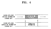
- the address searching unit 214c searches for the address of the correction information that coincides with the address of the switching section from the VCR correction information storage unit 215 (step S317). If the address of the correction information that coincides with the address of the switching section through the address searching unit 214c, the VCR control unit 214b operates the VCR unit 205 using the correction information that corresponds to the switching section, i.e., the correction information of the searched address section (step S319). If the driving of the VCR unit 205 by the correction information section that corresponds to the switching section is completed, the VCR control unit 214b again drives the VCR unit 205 by the VCR driving information stored in the VCR driving information storage unit 214a. In this case, the start point of the returned driving information becomes the address that corresponds to the end point of the switching section (See Figure 4 ).
- the DVDP/VCR combination system can compensate for the VCR driving information without replacing the VCR one-chip if an error occurs in the driving information stored in the VCR driving information storage unit in the VCR one-chip.
- the driving information can be compensated for through a simple procedure without replacing the VCR one-chip itself if an error occurs in the driving information stored in the VCR one-chip in the DVDP/VCR combination system, the cost for replacing components and the time required for correcting the driving information can be reduced.
Landscapes
- Engineering & Computer Science (AREA)
- Multimedia (AREA)
- Signal Processing (AREA)
- Television Signal Processing For Recording (AREA)
- Signal Processing For Digital Recording And Reproducing (AREA)
Claims (13)
- Kombinierte Vorrichtung für Videobänder und optische Medien, die eine Videobandwiedergabevorrichtung (205) und eine Lesevorrichtung (220) für optische Medien umfasst, wobei die Vorrichtung Folgendes umfasst:ein Steuermittel (214) zum Steuern der Videobandwiedergabevorrichtung (205), wobei das Steuermittel (214) ein Speichermittel (214a) enthält, das dafür konfiguriert ist, Steuerdaten zum Steuern der Videobandwiedergabevorrichtung (205) zu speichern, dadurch gekennzeichnet, dass die Vorrichtung des Weiteren Folgendes umfasst:einen nicht-flüchtigen Speicher (215), der dafür konfiguriert ist, Austauschsteuerdaten zu speichern, die über die Lesevorrichtung (220) für optische Medien erhalten wurde; undein Mittel (219) zum Umkonfigurieren des Steuermittels (214) zum Steuern der Videobandwiedergabevorrichtung (205) mittels der Austauschsteuerdaten.
- Vorrichtung nach Anspruch 1, wobei das Speichermittel (214a) in der Videobandwiedergabevorrichtung (205) angeordnet ist und die Vorrichtung Folgendes umfasst:ein weiteres Speichermittel (223a, 225) zum Speichern weiterer Steuerdaten für die Lesevorrichtung (220) für optische Medien;ein Deck (221) für optische Medien zum Erhalten der Austauschsteuerdaten;eine Umschaltsignaleingabeeinheit (210) zum Bereitstellen eines Umschaltsignals zum Umschalten der Steuerung der Videobandwiedergabevorrichtung (205) von einer Steuerung entsprechend den in dem Speichermittel (214a) gespeicherten Steuerdaten zu einer Steuerung entsprechend den Austauschsteuerdaten; undwobei das Steuermittel (214) die Videobandwiedergabevorrichtung (205) mittels der Austauschsteuerdaten in Reaktion auf das von der Umschaltsignaleingabeeinheit (210) bereitgestellte Umschaltsignal steuert.
- Vorrichtung nach Anspruch 2, wobei das weitere Speichermittel (223b, 225) Folgendes umfasst:eine Bereichstrennungsspeichereinheit (225) mit einem Videokassettenrekorderbereich zum Speichern der Austauschsteuerdaten für die Videobandwiedergabevorrichtung (205) und einen Optische-Medien-Informationsspeicherbereich zum Speichern von Optische-Medien-Austauschsteuerdaten, die von den optischen Medien abgerufen wurden.
- Vorrichtung nach Anspruch 3, wobei die Lesevorrichtung (220) für optische Medien einen Digitalvideodisk-Wiedergabevorrichtungschip (223) umfasst und wobei das Steuermittel (214) einen Videokassettenrekorderchip umfasst.
- Vorrichtung nach Anspruch 3 oder 4, wobei die Bereichstrennungsspeichereinheit (225) einen elektrisch löschbaren programmierbaren Nurlesespeicher EEPROM oder einen Nurlesespeicher ROM umfasst.
- Vorrichtung nach Anspruch 4, wobei die Bereichstrennungsspeichereinheit (225) von dem Digitalvideodisk-Wiedergabevorrichtungschip (223) und dem Videokassettenrekorderchip (214) getrennt ist.
- Vorrichtung nach einem der vorangehenden Ansprüche, die des Weiteren umfasst:eine Bildschirmanzeige OSD (260) zum Hinzufügen einer Bildschirmanzeigefunktion zu Videosignalen, die von der Vorrichtung ausgegeben werden.
- Vorrichtung nach einem der vorangehenden Ansprüche, die des Weiteren umfasst:einen Moving Picture Expert Group MPEG-Decoder (224) zum Verarbeiten von Videosignalen.
- Vorrichtung nach Anspruch 4, wobei der Videokassettenrekorderchip (214) des Weiteren umfasst:eine Adressensucheinheit (214c) zum Bereitstellen einer Korrekturinformationsadresse, die mit einer Umschaltsektionsadresse aus dem Speichermittel (214a) übereinstimmt.
- Verfahren zum Steuern einer kombinierten Vorrichtung für Videobänder und optische Medien, die eine Videobandwiedergabevorrichtung (205), eine Lesevorrichtung (220) für optische Medien und ein Steuermittel (214) zum Steuern der Videobandwiedergabevorrichtung (205) entsprechend Steuerdaten, die in einem Speichermittel (214a) gespeichert sind, umfasst, wobei das Verfahren gekennzeichnet ist durch:Speichern von Austauschsteuerdaten, die über die Lesevorrichtung (220) für optische Medien erhalten wurden, in einem nicht-flüchtigen Speicher (215); undUmkonfigurieren des Steuermittels (214) zum Steuern der Videobandwiedergabevorrichtung (205) mittels der Austauschsteuerdaten.
- Verfahren nach Anspruch 10, wobei das Speichermittel (214a) in der Videobandwiedergabevorrichtung (205) angeordnet ist und das Verfahren des Weiteren Folgendes umfasst:Speichern weiterer Steuerdaten zum Steuern der Lesevorrichtung (220) für optische Medien;Erhalten der Austauschsteuerdaten mit Hilfe eines Decks (221) für optische Medien;Bereitstellen eines Umschaltsignals zum Umschalten der Steuerung der Videobandwiedergabevorrichtung (205) von einer Steuerung entsprechend den in dem Speichermittel (214a) gespeicherten Steuerdaten zu einer Steuerung entsprechend den Austauschsteuerdaten; undSteuern der Videobandwiedergabevorrichtung (205) mittels der Austauschsteuerdaten in Reaktion auf das Umschaltsignal.
- Vorrichtung nach Anspruch 10 oder 11, die des Weiteren umfasst:Hinzufügen einer Bildschirmanzeigefunktion zu Videosignalen, die von der Vorrichtung ausgegeben werden.
- Vorrichtung nach Anspruch 10, 11 oder 12, die des Weiteren umfasst:Bereitstellen einer Korrekturinformationsadresse, die mit einer Umschaltsektionsadresse aus dem Speichermittel (214a) übereinstimmt.
Applications Claiming Priority (2)
| Application Number | Priority Date | Filing Date | Title |
|---|---|---|---|
| KR1020030054315A KR100761478B1 (ko) | 2003-08-06 | 2003-08-06 | Vcr 원칩의 구동정보의 보상이 가능한 dvdp/vcr콤비네이션 시스템 및 그 구동정보 보상방법 |
| KR2003054315 | 2003-08-06 |
Publications (2)
| Publication Number | Publication Date |
|---|---|
| EP1505590A1 EP1505590A1 (de) | 2005-02-09 |
| EP1505590B1 true EP1505590B1 (de) | 2008-04-16 |
Family
ID=33550317
Family Applications (1)
| Application Number | Title | Priority Date | Filing Date |
|---|---|---|---|
| EP04103343A Expired - Lifetime EP1505590B1 (de) | 2003-08-06 | 2004-07-13 | Kombiniertes Bandabspielgerät und Lesegerät für optische Datenträger |
Country Status (6)
| Country | Link |
|---|---|
| US (1) | US7450829B2 (de) |
| EP (1) | EP1505590B1 (de) |
| JP (1) | JP2005056546A (de) |
| KR (1) | KR100761478B1 (de) |
| CN (1) | CN1581328A (de) |
| DE (1) | DE602004013088T2 (de) |
Families Citing this family (1)
| Publication number | Priority date | Publication date | Assignee | Title |
|---|---|---|---|---|
| KR20060086730A (ko) * | 2005-01-27 | 2006-08-01 | 삼성전자주식회사 | 복합영상기기의 프로그램 수정방법 및 시스템 |
Family Cites Families (18)
| Publication number | Priority date | Publication date | Assignee | Title |
|---|---|---|---|---|
| JPS58106975A (ja) | 1981-12-21 | 1983-06-25 | Sanyo Electric Co Ltd | 情報処理装置 |
| DE3243812C2 (de) | 1982-11-26 | 1987-02-26 | Grundig E.M.V. Elektro-Mechanische Versuchsanstalt Max Grundig holländ. Stiftung & Co KG, 8510 Fürth | Funktionssteuerung für ein Tonbandgerät |
| JPH03186927A (ja) | 1989-12-18 | 1991-08-14 | Olympus Optical Co Ltd | マイクロコンピュータのプログラム変更装置 |
| JPH0371232A (ja) | 1989-08-10 | 1991-03-27 | Sanyo Electric Co Ltd | 電子機器 |
| US5293388A (en) | 1990-11-13 | 1994-03-08 | Hewlett-Packard Company | Compression/decompress with ECC data flow architecture |
| JPH0535457A (ja) | 1991-07-30 | 1993-02-12 | Matsushita Electric Ind Co Ltd | ワンチツプマイクロコンピユータ |
| JP3237103B2 (ja) | 1992-05-25 | 2001-12-10 | 船井電機株式会社 | 写真データの再生方法 |
| JP3748587B2 (ja) | 1995-03-16 | 2006-02-22 | 日立建機株式会社 | 建設機械の電子制御装置 |
| US5812883A (en) | 1995-11-22 | 1998-09-22 | Mitsubishi Chemical America, Inc. | System for reading and storing formatting information after formatting a first storage medium and using the stored formatting information to format a second storage medium |
| JPH10106242A (ja) | 1996-09-30 | 1998-04-24 | Sony Corp | 複合再生装置 |
| JPH11296364A (ja) | 1998-04-09 | 1999-10-29 | Alpine Electronics Inc | 車載用電子機器の記憶装置のデータ更新方法 |
| US20020064370A1 (en) * | 2000-06-15 | 2002-05-30 | John Berkheimer | Dual deck multimedia device |
| KR100395541B1 (ko) * | 2001-05-18 | 2003-08-25 | 삼성전자주식회사 | 콤비네이션 시스템 및 그에 적용되는 자동 복사 방법 |
| JP4613445B2 (ja) | 2001-05-22 | 2011-01-19 | ソニー株式会社 | 情報処理装置および方法、記録媒体、並びにプログラム |
| KR100395532B1 (ko) * | 2001-05-25 | 2003-08-25 | 삼성전자주식회사 | 복사되는 신호의 방식변환이 가능한 콤비네이션 시스템 및그의 신호 복사방법 |
| KR20020090022A (ko) * | 2001-05-25 | 2002-11-30 | 삼성전자 주식회사 | 선택된 동작패턴에 따라 동작하는 콤비네이션 시스템 |
| KR100732670B1 (ko) | 2001-07-28 | 2007-06-27 | 삼성전자주식회사 | 동작상태에 따른 외부기기 제어신호를 출력하는디브이디피와 브이씨알의 콤비네이션 시스템 |
| KR100740225B1 (ko) * | 2002-04-30 | 2007-07-18 | 삼성전자주식회사 | 전원의 재공급에 따른 동작상태를 복구할 수 있는 콤보시스템 및 방법 |
-
2003
- 2003-08-06 KR KR1020030054315A patent/KR100761478B1/ko not_active Expired - Fee Related
-
2004
- 2004-03-30 US US10/811,944 patent/US7450829B2/en not_active Expired - Fee Related
- 2004-03-31 JP JP2004108010A patent/JP2005056546A/ja active Pending
- 2004-07-02 CN CNA2004100621287A patent/CN1581328A/zh active Pending
- 2004-07-13 DE DE602004013088T patent/DE602004013088T2/de not_active Expired - Fee Related
- 2004-07-13 EP EP04103343A patent/EP1505590B1/de not_active Expired - Lifetime
Also Published As
| Publication number | Publication date |
|---|---|
| CN1581328A (zh) | 2005-02-16 |
| DE602004013088T2 (de) | 2008-11-20 |
| DE602004013088D1 (de) | 2008-05-29 |
| US7450829B2 (en) | 2008-11-11 |
| US20050031316A1 (en) | 2005-02-10 |
| JP2005056546A (ja) | 2005-03-03 |
| EP1505590A1 (de) | 2005-02-09 |
| KR20050015483A (ko) | 2005-02-21 |
| KR100761478B1 (ko) | 2007-09-27 |
Similar Documents
| Publication | Publication Date | Title |
|---|---|---|
| JP2004127471A (ja) | 記録装置及びその制御方法、並びに再生装置 | |
| CA2142441C (en) | Recording apparatus comprising a camera and a cassette which includes a separate memory for storing camera parameters | |
| KR100395567B1 (ko) | 설정치를 공유하는 콤비네이션 시스템 및 콤비네이션시스템의 환경 설정방법 | |
| US20060204220A1 (en) | Image recording and playing apparatus for automatically generating playlist using bookmark to-video recording format and playlist generating method thereof | |
| KR100740225B1 (ko) | 전원의 재공급에 따른 동작상태를 복구할 수 있는 콤보시스템 및 방법 | |
| US20050213931A1 (en) | Video data recording/reproducing apparatus and method | |
| EP1335379B1 (de) | Abspielgerät für Aufzeichnungsträger | |
| EP1505590A1 (de) | Kombiniertes Bandabspielgerät und Lesegerät für optische Datenträger | |
| US20060002261A1 (en) | Data reproduction apparatus having resume reproduction function, and program product for implementing resume reproduction function | |
| JP2003087748A (ja) | 光ディスク再生装置 | |
| EP1353328A2 (de) | Vorrichtung zur Wiedergabe eines Aufnahmemediums | |
| KR100530228B1 (ko) | 내부의 장치간에 동작명령의 전송이 가능한 콤비네이션시스템 및 그의 동작제어방법 | |
| KR100406992B1 (ko) | 하나의 오에스디 화면을 통해 각 장치의 제어가 가능한콤비네이션 시스템 | |
| US20060062545A1 (en) | Combination recording apparatus to automatically set relay recording and method thereof | |
| EP1450557A2 (de) | Vorrichtung und Verfahren zum Anzeigen eines OSD-Bildes in einer kombinierten Videoeinrichtung | |
| KR100513330B1 (ko) | 복합 영상기기에서의 오에스디 영상 표시장치 및 방법 | |
| KR100518831B1 (ko) | 콤비네이션 시스템 제어 방법 및 장치 | |
| KR100513329B1 (ko) | 복합 영상기기에서의 오에스디 영상 표시장치 및 방법 | |
| KR20020090022A (ko) | 선택된 동작패턴에 따라 동작하는 콤비네이션 시스템 | |
| US20060051051A1 (en) | Combination recording apparatus for simultaneous recording and method thereof | |
| KR20040064015A (ko) | 개선된 pvr 기능을 갖는 영상 표시 기기 및 그 방법 | |
| US20060093313A1 (en) | Combination recording apparatus for auto-selecting record apparatus to use referring to apparatus using status and method thereof | |
| US20060098939A1 (en) | Combination system capable of controlling each device through a single OSD menu and method thereof | |
| KR20050011066A (ko) | 콤비네이션 시스템 및 콤비네이션 시스템을 구성하는전자기기간의 동작전환방법 | |
| JP2006294164A (ja) | ディスク記録装置および方法 |
Legal Events
| Date | Code | Title | Description |
|---|---|---|---|
| PUAI | Public reference made under article 153(3) epc to a published international application that has entered the european phase |
Free format text: ORIGINAL CODE: 0009012 |
|
| AK | Designated contracting states |
Kind code of ref document: A1 Designated state(s): AT BE BG CH CY CZ DE DK EE ES FI FR GB GR HU IE IT LI LU MC NL PL PT RO SE SI SK TR |
|
| AX | Request for extension of the european patent |
Extension state: AL HR LT LV MK |
|
| 17P | Request for examination filed |
Effective date: 20050528 |
|
| 17Q | First examination report despatched |
Effective date: 20050629 |
|
| AKX | Designation fees paid |
Designated state(s): DE GB IT NL |
|
| 17Q | First examination report despatched |
Effective date: 20050629 |
|
| GRAP | Despatch of communication of intention to grant a patent |
Free format text: ORIGINAL CODE: EPIDOSNIGR1 |
|
| GRAC | Information related to communication of intention to grant a patent modified |
Free format text: ORIGINAL CODE: EPIDOSCIGR1 |
|
| GRAS | Grant fee paid |
Free format text: ORIGINAL CODE: EPIDOSNIGR3 |
|
| GRAA | (expected) grant |
Free format text: ORIGINAL CODE: 0009210 |
|
| AK | Designated contracting states |
Kind code of ref document: B1 Designated state(s): DE GB IT NL |
|
| REF | Corresponds to: |
Ref document number: 602004013088 Country of ref document: DE Date of ref document: 20080529 Kind code of ref document: P |
|
| PGFP | Annual fee paid to national office [announced via postgrant information from national office to epo] |
Ref country code: DE Payment date: 20080505 Year of fee payment: 5 |
|
| PGFP | Annual fee paid to national office [announced via postgrant information from national office to epo] |
Ref country code: NL Payment date: 20080724 Year of fee payment: 5 |
|
| PGFP | Annual fee paid to national office [announced via postgrant information from national office to epo] |
Ref country code: GB Payment date: 20080702 Year of fee payment: 5 |
|
| PLBE | No opposition filed within time limit |
Free format text: ORIGINAL CODE: 0009261 |
|
| STAA | Information on the status of an ep patent application or granted ep patent |
Free format text: STATUS: NO OPPOSITION FILED WITHIN TIME LIMIT |
|
| 26N | No opposition filed |
Effective date: 20090119 |
|
| PG25 | Lapsed in a contracting state [announced via postgrant information from national office to epo] |
Ref country code: IT Free format text: LAPSE BECAUSE OF FAILURE TO SUBMIT A TRANSLATION OF THE DESCRIPTION OR TO PAY THE FEE WITHIN THE PRESCRIBED TIME-LIMIT Effective date: 20080416 |
|
| GBPC | Gb: european patent ceased through non-payment of renewal fee |
Effective date: 20090713 |
|
| NLV4 | Nl: lapsed or anulled due to non-payment of the annual fee |
Effective date: 20100201 |
|
| PG25 | Lapsed in a contracting state [announced via postgrant information from national office to epo] |
Ref country code: GB Free format text: LAPSE BECAUSE OF NON-PAYMENT OF DUE FEES Effective date: 20090713 |
|
| PG25 | Lapsed in a contracting state [announced via postgrant information from national office to epo] |
Ref country code: DE Free format text: LAPSE BECAUSE OF NON-PAYMENT OF DUE FEES Effective date: 20100202 |
|
| PG25 | Lapsed in a contracting state [announced via postgrant information from national office to epo] |
Ref country code: NL Free format text: LAPSE BECAUSE OF NON-PAYMENT OF DUE FEES Effective date: 20100201 |