EP1511046A1 - Procede de fabrication d'un aimant permanent resistant a la corrosion a base de terres rares, aimant permanent resistant a la corrosion a base de terres rares, procede de revetement par immersion et rotation pour piece a usiner et procede pour former un film de revetement sur une piece a usiner - Google Patents
Procede de fabrication d'un aimant permanent resistant a la corrosion a base de terres rares, aimant permanent resistant a la corrosion a base de terres rares, procede de revetement par immersion et rotation pour piece a usiner et procede pour former un film de revetement sur une piece a usiner Download PDFInfo
- Publication number
- EP1511046A1 EP1511046A1 EP03812349A EP03812349A EP1511046A1 EP 1511046 A1 EP1511046 A1 EP 1511046A1 EP 03812349 A EP03812349 A EP 03812349A EP 03812349 A EP03812349 A EP 03812349A EP 1511046 A1 EP1511046 A1 EP 1511046A1
- Authority
- EP
- European Patent Office
- Prior art keywords
- rare earth
- based permanent
- corrosion
- turn table
- earth metal
- Prior art date
- Legal status (The legal status is an assumption and is not a legal conclusion. Google has not performed a legal analysis and makes no representation as to the accuracy of the status listed.)
- Granted
Links
Images



Classifications
-
- H—ELECTRICITY
- H01—ELECTRIC ELEMENTS
- H01F—MAGNETS; INDUCTANCES; TRANSFORMERS; SELECTION OF MATERIALS FOR THEIR MAGNETIC PROPERTIES
- H01F1/00—Magnets or magnetic bodies characterised by the magnetic materials therefor; Selection of materials for their magnetic properties
- H01F1/01—Magnets or magnetic bodies characterised by the magnetic materials therefor; Selection of materials for their magnetic properties of inorganic materials
- H01F1/03—Magnets or magnetic bodies characterised by the magnetic materials therefor; Selection of materials for their magnetic properties of inorganic materials characterised by their coercivity
- H01F1/032—Magnets or magnetic bodies characterised by the magnetic materials therefor; Selection of materials for their magnetic properties of inorganic materials characterised by their coercivity of hard-magnetic materials
- H01F1/04—Magnets or magnetic bodies characterised by the magnetic materials therefor; Selection of materials for their magnetic properties of inorganic materials characterised by their coercivity of hard-magnetic materials metals or alloys
- H01F1/047—Alloys characterised by their composition
- H01F1/053—Alloys characterised by their composition containing rare earth metals
-
- B—PERFORMING OPERATIONS; TRANSPORTING
- B05—SPRAYING OR ATOMISING IN GENERAL; APPLYING FLUENT MATERIALS TO SURFACES, IN GENERAL
- B05C—APPARATUS FOR APPLYING FLUENT MATERIALS TO SURFACES, IN GENERAL
- B05C11/00—Component parts, details or accessories not specifically provided for in groups B05C1/00 - B05C9/00
- B05C11/02—Apparatus for spreading or distributing liquids or other fluent materials already applied to a surface ; Controlling means therefor; Control of the thickness of a coating by spreading or distributing liquids or other fluent materials already applied to the coated surface
- B05C11/08—Spreading liquid or other fluent material by manipulating the work, e.g. tilting
-
- B—PERFORMING OPERATIONS; TRANSPORTING
- B05—SPRAYING OR ATOMISING IN GENERAL; APPLYING FLUENT MATERIALS TO SURFACES, IN GENERAL
- B05C—APPARATUS FOR APPLYING FLUENT MATERIALS TO SURFACES, IN GENERAL
- B05C13/00—Means for manipulating or holding work, e.g. for separate articles
- B05C13/02—Means for manipulating or holding work, e.g. for separate articles for particular articles
-
- B—PERFORMING OPERATIONS; TRANSPORTING
- B05—SPRAYING OR ATOMISING IN GENERAL; APPLYING FLUENT MATERIALS TO SURFACES, IN GENERAL
- B05C—APPARATUS FOR APPLYING FLUENT MATERIALS TO SURFACES, IN GENERAL
- B05C3/00—Apparatus in which the work is brought into contact with a bulk quantity of liquid or other fluent material
- B05C3/02—Apparatus in which the work is brought into contact with a bulk quantity of liquid or other fluent material the work being immersed in the liquid or other fluent material
- B05C3/09—Apparatus in which the work is brought into contact with a bulk quantity of liquid or other fluent material the work being immersed in the liquid or other fluent material for treating separate articles
-
- C—CHEMISTRY; METALLURGY
- C23—COATING METALLIC MATERIAL; COATING MATERIAL WITH METALLIC MATERIAL; CHEMICAL SURFACE TREATMENT; DIFFUSION TREATMENT OF METALLIC MATERIAL; COATING BY VACUUM EVAPORATION, BY SPUTTERING, BY ION IMPLANTATION OR BY CHEMICAL VAPOUR DEPOSITION, IN GENERAL; INHIBITING CORROSION OF METALLIC MATERIAL OR INCRUSTATION IN GENERAL
- C23C—COATING METALLIC MATERIAL; COATING MATERIAL WITH METALLIC MATERIAL; SURFACE TREATMENT OF METALLIC MATERIAL BY DIFFUSION INTO THE SURFACE, BY CHEMICAL CONVERSION OR SUBSTITUTION; COATING BY VACUUM EVAPORATION, BY SPUTTERING, BY ION IMPLANTATION OR BY CHEMICAL VAPOUR DEPOSITION, IN GENERAL
- C23C2/00—Hot-dipping or immersion processes for applying the coating material in the molten state without affecting the shape; Apparatus therefor
- C23C2/04—Hot-dipping or immersion processes for applying the coating material in the molten state without affecting the shape; Apparatus therefor characterised by the coating material
-
- C—CHEMISTRY; METALLURGY
- C23—COATING METALLIC MATERIAL; COATING MATERIAL WITH METALLIC MATERIAL; CHEMICAL SURFACE TREATMENT; DIFFUSION TREATMENT OF METALLIC MATERIAL; COATING BY VACUUM EVAPORATION, BY SPUTTERING, BY ION IMPLANTATION OR BY CHEMICAL VAPOUR DEPOSITION, IN GENERAL; INHIBITING CORROSION OF METALLIC MATERIAL OR INCRUSTATION IN GENERAL
- C23C—COATING METALLIC MATERIAL; COATING MATERIAL WITH METALLIC MATERIAL; SURFACE TREATMENT OF METALLIC MATERIAL BY DIFFUSION INTO THE SURFACE, BY CHEMICAL CONVERSION OR SUBSTITUTION; COATING BY VACUUM EVAPORATION, BY SPUTTERING, BY ION IMPLANTATION OR BY CHEMICAL VAPOUR DEPOSITION, IN GENERAL
- C23C24/00—Coating starting from inorganic powder
- C23C24/08—Coating starting from inorganic powder by application of heat or pressure and heat
-
- C—CHEMISTRY; METALLURGY
- C23—COATING METALLIC MATERIAL; COATING MATERIAL WITH METALLIC MATERIAL; CHEMICAL SURFACE TREATMENT; DIFFUSION TREATMENT OF METALLIC MATERIAL; COATING BY VACUUM EVAPORATION, BY SPUTTERING, BY ION IMPLANTATION OR BY CHEMICAL VAPOUR DEPOSITION, IN GENERAL; INHIBITING CORROSION OF METALLIC MATERIAL OR INCRUSTATION IN GENERAL
- C23C—COATING METALLIC MATERIAL; COATING MATERIAL WITH METALLIC MATERIAL; SURFACE TREATMENT OF METALLIC MATERIAL BY DIFFUSION INTO THE SURFACE, BY CHEMICAL CONVERSION OR SUBSTITUTION; COATING BY VACUUM EVAPORATION, BY SPUTTERING, BY ION IMPLANTATION OR BY CHEMICAL VAPOUR DEPOSITION, IN GENERAL
- C23C24/00—Coating starting from inorganic powder
- C23C24/08—Coating starting from inorganic powder by application of heat or pressure and heat
- C23C24/10—Coating starting from inorganic powder by application of heat or pressure and heat with intermediate formation of a liquid phase in the layer
-
- C—CHEMISTRY; METALLURGY
- C23—COATING METALLIC MATERIAL; COATING MATERIAL WITH METALLIC MATERIAL; CHEMICAL SURFACE TREATMENT; DIFFUSION TREATMENT OF METALLIC MATERIAL; COATING BY VACUUM EVAPORATION, BY SPUTTERING, BY ION IMPLANTATION OR BY CHEMICAL VAPOUR DEPOSITION, IN GENERAL; INHIBITING CORROSION OF METALLIC MATERIAL OR INCRUSTATION IN GENERAL
- C23C—COATING METALLIC MATERIAL; COATING MATERIAL WITH METALLIC MATERIAL; SURFACE TREATMENT OF METALLIC MATERIAL BY DIFFUSION INTO THE SURFACE, BY CHEMICAL CONVERSION OR SUBSTITUTION; COATING BY VACUUM EVAPORATION, BY SPUTTERING, BY ION IMPLANTATION OR BY CHEMICAL VAPOUR DEPOSITION, IN GENERAL
- C23C26/00—Coating not provided for in groups C23C2/00 - C23C24/00
-
- C—CHEMISTRY; METALLURGY
- C23—COATING METALLIC MATERIAL; COATING MATERIAL WITH METALLIC MATERIAL; CHEMICAL SURFACE TREATMENT; DIFFUSION TREATMENT OF METALLIC MATERIAL; COATING BY VACUUM EVAPORATION, BY SPUTTERING, BY ION IMPLANTATION OR BY CHEMICAL VAPOUR DEPOSITION, IN GENERAL; INHIBITING CORROSION OF METALLIC MATERIAL OR INCRUSTATION IN GENERAL
- C23C—COATING METALLIC MATERIAL; COATING MATERIAL WITH METALLIC MATERIAL; SURFACE TREATMENT OF METALLIC MATERIAL BY DIFFUSION INTO THE SURFACE, BY CHEMICAL CONVERSION OR SUBSTITUTION; COATING BY VACUUM EVAPORATION, BY SPUTTERING, BY ION IMPLANTATION OR BY CHEMICAL VAPOUR DEPOSITION, IN GENERAL
- C23C26/00—Coating not provided for in groups C23C2/00 - C23C24/00
- C23C26/02—Coating not provided for in groups C23C2/00 - C23C24/00 applying molten material to the substrate
-
- H—ELECTRICITY
- H01—ELECTRIC ELEMENTS
- H01F—MAGNETS; INDUCTANCES; TRANSFORMERS; SELECTION OF MATERIALS FOR THEIR MAGNETIC PROPERTIES
- H01F1/00—Magnets or magnetic bodies characterised by the magnetic materials therefor; Selection of materials for their magnetic properties
- H01F1/01—Magnets or magnetic bodies characterised by the magnetic materials therefor; Selection of materials for their magnetic properties of inorganic materials
- H01F1/03—Magnets or magnetic bodies characterised by the magnetic materials therefor; Selection of materials for their magnetic properties of inorganic materials characterised by their coercivity
- H01F1/032—Magnets or magnetic bodies characterised by the magnetic materials therefor; Selection of materials for their magnetic properties of inorganic materials characterised by their coercivity of hard-magnetic materials
- H01F1/04—Magnets or magnetic bodies characterised by the magnetic materials therefor; Selection of materials for their magnetic properties of inorganic materials characterised by their coercivity of hard-magnetic materials metals or alloys
- H01F1/047—Alloys characterised by their composition
- H01F1/053—Alloys characterised by their composition containing rare earth metals
- H01F1/055—Alloys characterised by their composition containing rare earth metals and magnetic transition metals, e.g. SmCo5
- H01F1/057—Alloys characterised by their composition containing rare earth metals and magnetic transition metals, e.g. SmCo5 and IIIa elements, e.g. Nd2Fe14B
- H01F1/0571—Alloys characterised by their composition containing rare earth metals and magnetic transition metals, e.g. SmCo5 and IIIa elements, e.g. Nd2Fe14B in the form of particles, e.g. rapid quenched powders or ribbon flakes
- H01F1/0575—Alloys characterised by their composition containing rare earth metals and magnetic transition metals, e.g. SmCo5 and IIIa elements, e.g. Nd2Fe14B in the form of particles, e.g. rapid quenched powders or ribbon flakes pressed, sintered or bonded together
- H01F1/0577—Alloys characterised by their composition containing rare earth metals and magnetic transition metals, e.g. SmCo5 and IIIa elements, e.g. Nd2Fe14B in the form of particles, e.g. rapid quenched powders or ribbon flakes pressed, sintered or bonded together sintered
-
- H—ELECTRICITY
- H01—ELECTRIC ELEMENTS
- H01F—MAGNETS; INDUCTANCES; TRANSFORMERS; SELECTION OF MATERIALS FOR THEIR MAGNETIC PROPERTIES
- H01F1/00—Magnets or magnetic bodies characterised by the magnetic materials therefor; Selection of materials for their magnetic properties
- H01F1/01—Magnets or magnetic bodies characterised by the magnetic materials therefor; Selection of materials for their magnetic properties of inorganic materials
- H01F1/03—Magnets or magnetic bodies characterised by the magnetic materials therefor; Selection of materials for their magnetic properties of inorganic materials characterised by their coercivity
- H01F1/032—Magnets or magnetic bodies characterised by the magnetic materials therefor; Selection of materials for their magnetic properties of inorganic materials characterised by their coercivity of hard-magnetic materials
- H01F1/04—Magnets or magnetic bodies characterised by the magnetic materials therefor; Selection of materials for their magnetic properties of inorganic materials characterised by their coercivity of hard-magnetic materials metals or alloys
- H01F1/047—Alloys characterised by their composition
- H01F1/053—Alloys characterised by their composition containing rare earth metals
- H01F1/055—Alloys characterised by their composition containing rare earth metals and magnetic transition metals, e.g. SmCo5
- H01F1/057—Alloys characterised by their composition containing rare earth metals and magnetic transition metals, e.g. SmCo5 and IIIa elements, e.g. Nd2Fe14B
- H01F1/0571—Alloys characterised by their composition containing rare earth metals and magnetic transition metals, e.g. SmCo5 and IIIa elements, e.g. Nd2Fe14B in the form of particles, e.g. rapid quenched powders or ribbon flakes
- H01F1/0575—Alloys characterised by their composition containing rare earth metals and magnetic transition metals, e.g. SmCo5 and IIIa elements, e.g. Nd2Fe14B in the form of particles, e.g. rapid quenched powders or ribbon flakes pressed, sintered or bonded together
- H01F1/0578—Alloys characterised by their composition containing rare earth metals and magnetic transition metals, e.g. SmCo5 and IIIa elements, e.g. Nd2Fe14B in the form of particles, e.g. rapid quenched powders or ribbon flakes pressed, sintered or bonded together bonded together
-
- H—ELECTRICITY
- H01—ELECTRIC ELEMENTS
- H01F—MAGNETS; INDUCTANCES; TRANSFORMERS; SELECTION OF MATERIALS FOR THEIR MAGNETIC PROPERTIES
- H01F1/00—Magnets or magnetic bodies characterised by the magnetic materials therefor; Selection of materials for their magnetic properties
- H01F1/01—Magnets or magnetic bodies characterised by the magnetic materials therefor; Selection of materials for their magnetic properties of inorganic materials
- H01F1/03—Magnets or magnetic bodies characterised by the magnetic materials therefor; Selection of materials for their magnetic properties of inorganic materials characterised by their coercivity
- H01F1/032—Magnets or magnetic bodies characterised by the magnetic materials therefor; Selection of materials for their magnetic properties of inorganic materials characterised by their coercivity of hard-magnetic materials
- H01F1/04—Magnets or magnetic bodies characterised by the magnetic materials therefor; Selection of materials for their magnetic properties of inorganic materials characterised by their coercivity of hard-magnetic materials metals or alloys
- H01F1/047—Alloys characterised by their composition
- H01F1/053—Alloys characterised by their composition containing rare earth metals
- H01F1/055—Alloys characterised by their composition containing rare earth metals and magnetic transition metals, e.g. SmCo5
- H01F1/059—Alloys characterised by their composition containing rare earth metals and magnetic transition metals, e.g. SmCo5 and Va elements, e.g. Sm2Fe17N2
-
- H—ELECTRICITY
- H01—ELECTRIC ELEMENTS
- H01F—MAGNETS; INDUCTANCES; TRANSFORMERS; SELECTION OF MATERIALS FOR THEIR MAGNETIC PROPERTIES
- H01F41/00—Apparatus or processes specially adapted for manufacturing or assembling magnets, inductances or transformers; Apparatus or processes specially adapted for manufacturing materials characterised by their magnetic properties
- H01F41/02—Apparatus or processes specially adapted for manufacturing or assembling magnets, inductances or transformers; Apparatus or processes specially adapted for manufacturing materials characterised by their magnetic properties for manufacturing cores, coils, or magnets
- H01F41/0253—Apparatus or processes specially adapted for manufacturing or assembling magnets, inductances or transformers; Apparatus or processes specially adapted for manufacturing materials characterised by their magnetic properties for manufacturing cores, coils, or magnets for manufacturing permanent magnets
- H01F41/026—Apparatus or processes specially adapted for manufacturing or assembling magnets, inductances or transformers; Apparatus or processes specially adapted for manufacturing materials characterised by their magnetic properties for manufacturing cores, coils, or magnets for manufacturing permanent magnets protecting methods against environmental influences, e.g. oxygen, by surface treatment
-
- Y—GENERAL TAGGING OF NEW TECHNOLOGICAL DEVELOPMENTS; GENERAL TAGGING OF CROSS-SECTIONAL TECHNOLOGIES SPANNING OVER SEVERAL SECTIONS OF THE IPC; TECHNICAL SUBJECTS COVERED BY FORMER USPC CROSS-REFERENCE ART COLLECTIONS [XRACs] AND DIGESTS
- Y02—TECHNOLOGIES OR APPLICATIONS FOR MITIGATION OR ADAPTATION AGAINST CLIMATE CHANGE
- Y02T—CLIMATE CHANGE MITIGATION TECHNOLOGIES RELATED TO TRANSPORTATION
- Y02T50/00—Aeronautics or air transport
- Y02T50/60—Efficient propulsion technologies, e.g. for aircraft
-
- Y—GENERAL TAGGING OF NEW TECHNOLOGICAL DEVELOPMENTS; GENERAL TAGGING OF CROSS-SECTIONAL TECHNOLOGIES SPANNING OVER SEVERAL SECTIONS OF THE IPC; TECHNICAL SUBJECTS COVERED BY FORMER USPC CROSS-REFERENCE ART COLLECTIONS [XRACs] AND DIGESTS
- Y10—TECHNICAL SUBJECTS COVERED BY FORMER USPC
- Y10T—TECHNICAL SUBJECTS COVERED BY FORMER US CLASSIFICATION
- Y10T428/00—Stock material or miscellaneous articles
- Y10T428/12—All metal or with adjacent metals
- Y10T428/12014—All metal or with adjacent metals having metal particles
- Y10T428/12028—Composite; i.e., plural, adjacent, spatially distinct metal components [e.g., layers, etc.]
- Y10T428/12063—Nonparticulate metal component
-
- Y—GENERAL TAGGING OF NEW TECHNOLOGICAL DEVELOPMENTS; GENERAL TAGGING OF CROSS-SECTIONAL TECHNOLOGIES SPANNING OVER SEVERAL SECTIONS OF THE IPC; TECHNICAL SUBJECTS COVERED BY FORMER USPC CROSS-REFERENCE ART COLLECTIONS [XRACs] AND DIGESTS
- Y10—TECHNICAL SUBJECTS COVERED BY FORMER USPC
- Y10T—TECHNICAL SUBJECTS COVERED BY FORMER US CLASSIFICATION
- Y10T428/00—Stock material or miscellaneous articles
- Y10T428/12—All metal or with adjacent metals
- Y10T428/12465—All metal or with adjacent metals having magnetic properties, or preformed fiber orientation coordinate with shape
-
- Y—GENERAL TAGGING OF NEW TECHNOLOGICAL DEVELOPMENTS; GENERAL TAGGING OF CROSS-SECTIONAL TECHNOLOGIES SPANNING OVER SEVERAL SECTIONS OF THE IPC; TECHNICAL SUBJECTS COVERED BY FORMER USPC CROSS-REFERENCE ART COLLECTIONS [XRACs] AND DIGESTS
- Y10—TECHNICAL SUBJECTS COVERED BY FORMER USPC
- Y10T—TECHNICAL SUBJECTS COVERED BY FORMER US CLASSIFICATION
- Y10T428/00—Stock material or miscellaneous articles
- Y10T428/32—Composite [nonstructural laminate] of inorganic material having metal-compound-containing layer and having defined magnetic layer
- Y10T428/325—Magnetic layer next to second metal compound-containing layer
Definitions
- the present invention relates to a stable and simple method for producing a rare earth metal-based permanent magnet having on the surface thereof a corrosion-resistant film containing fine zinc particles dispersed therein, a corrosion-resistant rare earth metal-based permanent magnet produced by the method, a dip spin coating method being suitable for forming a coating film on thin type work pieces having various shapes, and a method for forming a coating film on a work piece.
- Rare earth metal-based permanent magnets for instance, R-Fe-B based permanent magnets represented by a Nd-Fe-B based permanent magnet, or R-Fe-N based permanent magnets represented by a Sm-Fe-N based permanent magnet, etc. , utilize inexpensive materials abundant in resources and possess high magnetic properties, and particularly among them, R-Fe-B based permanent magnets are employed today in various fields.
- rare earth metal-based permanent magnets contain a highly reactive rare earth element: R, they are apt to be oxidized and corroded in ambient, and in case they are used without applying any surface treatment, corrosion tends to proceed from the surface in the presence of small acidic or alkaline substance or water to generate rust, and this brings about the degradation and the fluctuation inmagnetic properties.
- a rusty magnet is embedded in a magnetic circuit and a like device, there is fear of scattering rust as to contaminate peripheral components.
- Patent literature 1 Japanese Patent Laid-Open No. 2000-182813 (Patent literature 1) is proposed a method comprising coating the surface of the rare earth metal-based permanent magnet with a treating solution comprising an aqueous solution of alkali silicate having dispersed therein fine zinc particles, and then applying a heat treatment thereto to obtain a corrosion-resistant film containing fine zinc particles dispersed therein.
- This method utilizes the anti-corrosive function of the film using alkali silicate as the starting raw material and the sacrificial anti-corrosive function of the fine zinc particles that is potentially base, and is expected as a method capable of imparting high corrosion resistance to the rare earth metal-based permanent magnets.
- this method requires the treating solution to be kept alkaline in order to maintain the fine zinc particles uniformly dispersed in the treating solution; thus, in case the treating solution is applied to the surface of the rare earth metal-based permanent magnet, hydroxides of the metal which constitutes the magnet generate on the surface of the magnet, and, due to the layer comprising such metal hydroxides covering the surface of the magnet, there occur problems such as a difficulty in forming a corrosion-resistant film containing fine zinc particles dispersed therein with high adhesive strength, a tendency in generating cracks due to the poor flexibility of the film using alkali silicate as the starting raw material, a troublesome waste liquid treatment, and the like.
- Patent literature 2 Japanese Patent Laid-Open No. 2001-143949 (Patent literature 2) is proposed a method comprising coating the surface of the rare earth metal-based permanent magnet with a treating solution containing silico-organic compound and inorganic fine particles having an average particle diameter of 1 nm to 100 nm, and then applying a heat treatment thereto to obtain a corrosion-resistant film containing fine inorganic particles dispersed therein.
- This method is proposed in order to form a thin and dense corrosion-resistant film on the surface of the rare earth metal-based permanent magnet using a silico-organic compound as the starting raw material; the internal stress inside the film which forms during the process of the film formation can be relaxed by dispersing fine inorganic particles having the specified average particle diameter in the film component, and hence, the generation of physical defects such as cracks can be thereby prevented from occurring.
- This method is also expected as a method capable of imparting high corrosion resistance to the rare earth metal-based permanent magnets.
- the thus prepared treating solution is acidic, in case the treating solution is applied to the surface of the rare earth metal-based permanent magnet, there occur problems such as inducing corrosion of the magnet, or causing the fluctuation in the composition of the treating solution due to the volatilization of the organic solvent; furthermore, there are problems such as causing unfavorable influences to the environment, or requiring a troublesome waste solution treatment.
- the objectives of the present invention are to provide a stable and simple method for producing a rare earth metal-based permanent magnet having on the surface thereof a corrosion-resistant film containing fine zinc particles dispersed therein, a corrosion-resistant rare earth metal-based permanent magnet produced by the method, a dip spin coating method being suitable for forming a coating film on thin type work pieces having various shapes, and a method for forming a coating film on a work piece.
- a method for producing a corrosion-resistant rare earth metal-based permanent magnet characterized in that it comprises providing an aqueous treating fluid, which contains a hydrolysis polymerization product of alkyl silicate and fine zinc particles having an average particle diameter of 1 ⁇ m to 50 ⁇ m and has a pH value of 6 to 8 and a viscosity of 1000 cP or less, applying the fluid on the surface of a rare earth metal-based permanent magnet, and subjecting the resultant magnet to a heat treatment at 250°C to 400°C, to thereby form a corrosion-resistant film containing fine zinc particles dispersed therein.
- the fine zinc particles are flaky particles.
- the total content of alkyl silicate as the starting raw material and fine zinc particles in the aqueous treating fluid accounts for 40 wt.% to 90 wt.% (where alkyl silicate content is converted to SiO 2 content).
- the mixing ratio of alkyl silicate as the starting raw material and fine zinc particles in the aqueous treating fluid is 1:1 to 1:19 (in weight ratio: where alkyl silicate content is converted to SiO 2 content).
- an organic dispersing agent is added in the aqueous treating fluid.
- the film thickness of the corrosion-resistant film containing fine zinc particles dispersed therein is 1 ⁇ m to 50 ⁇ m.
- other fine inorganic particles are additionally dispersed in the corrosion-resistant film containing fine zinc particles dispersed therein.
- the aqueous treating fluid is applied to the surface of the rare earth metal-based permanent magnet by a dip spin coating method.
- the method is carried out by using an aqueous treating fluid having a viscosity of 300 cP to 600 cP.
- the dip spin coating is carried out by supporting plural rare earth metal-based permanent magnets on approximately the outer peripheral edge portion of a turn table which is rotatable around a vertical center axis that is used as the axis of rotation, immersion coating the rare earth metal-based permanent magnets with the aqueous treating fluid by immersing the turn table having the rare earth metal-based permanent magnets supported thereon in an aqueous treating fluid tank, and after taking out the resulting turn table from the liquid, rotating the turn table to centrifugally cut off the aqueous treating fluid that has adhered in excess to the rare earth metal-based permanent magnets.
- the plural rare earth metal-based permanent magnets are supported in approximately a ring-like arrangement on approximately the outer peripheral edge portion of the turn table.
- the rare earth metal-based permanent magnets are thin type magnets.
- the thin type magnets are supported in such a manner that the widest plane of the thin type magnet is disposed approximately in parallel with the radial direction of the turn table.
- a coating jig is used as such that in case of attaching it on approximately the outer peripheral edge portion of the turn table, each of the thin type magnets is set apart from each other with the widest plane thereof being placed approximately in parallel with the radial direction of the turn table and in approximately a ring-like arrangement.
- the thin type magnets are shaped in one of the shapes selected from planar, ring-like, and arc-like shape.
- the coating jig is detached from the turn table while leaving the thin type magnets still set thereon, and the thin type magnets still set on the coating jig are subjected to a heat treatment at an arbitrary place.
- a rare earth metal-based permanent magnet characterized by having on the surface thereof a corrosion-resistant film containing fine zinc particles having an average particle diameter of 1 ⁇ m to 50 ⁇ m being dispersed in the film component using alkyl silicate as the starting raw material.
- the corrosion-resistant film contains 50 wt.% to 95 wt.% of fine zinc particles.
- zinc is diffused from the surface of the magnet body to the internal part.
- a dip spin coating method for work pieces characterized in that it comprises supporting plural work pieces on approximately the outer peripheral edge portion of a turn table which is rotatable around a vertical center axis that is used as the axis of rotation, immersion coating the work pieces with a paint by immersing the turn table having the work pieces supported thereon in a paint tank, and after taking out the resulting turn table from the liquid, rotating the turn table to centrifugally cut off the paint that has adhered in excess to the work pieces.
- a method for forming a coating film on a work piece characterized in that it comprises, a coating jig is used as such that in case of attaching it on approximately the outer peripheral edge portion of a turn table which is rotatable around a vertical center axis that is used as the axis of rotation, each of work pieces is set apart from each other in approximately a ring-like arrangement, and it further comprises immersion coating the work pieces with a paint by immersing the turn table on which the coating jig having the work pieces set thereon is attached in a paint tank; taking out the resulting turn table from the liquid and rotating the turn table to centrifugally cut off the paint that has adhered in excess to the work pieces; detaching, from the turn table, the coating jig having the work pieces still set thereon; and if desired, subjecting the work pieces still set on the coating jig to a dry treatment at an arbitrary place.
- a corrosion-resistant film containing fine zinc particles dispersed therein is formed by applying an aqueous treating fluid which contains a hydrolysis polymerization product of alkyl silicate and fine zinc particles having an average particle diameter of 1 ⁇ m to 50 ⁇ m and has a pH value of 6 to 8 and a viscosity of 1000 cP or less on the surface of a rare earth metal-based permanent magnet, followed by then subjecting the resultant magnet to a heat treatment at 250°C to 400°C.
- the thus formed corrosion-resistant film containing fine zinc particles dispersed therein not only imparts high corrosion resistance to the rare earth metal-based permanent magnet, but also has high adhesive strength because zinc is internally diffused from the surface of the magnet body.
- Alkyl silicates used herein are such expressed by the general formula: Si n O (n-1) (OR) (2n+2) .
- R represents an alkyl group exemplified by lower alkyl groups having 1 to 4 carbon atoms, such as methyl group, ethyl group, propyl group, butyl group, and the like, but suitable among them is ethyl group (i.e., ethyl silicate) because it not only is inexpensive, but also is nontoxic and has superior handling properties.
- n represents 1 or higher integer, however, in order to form a dense film, n preferably is an integer of 10 or lower.
- fine zinc particles having an average particle diameter of 1 ⁇ m to 50 ⁇ m are used. This is because, if the average particle diameter is smaller than 1 ⁇ m, it is feared that the fine zinc particles undergo secondary aggregation in the aqueous treating fluid; on the other hand, if the average particle diameter is larger than 50 ⁇ m, it is feared that the fine zinc particles sediment in the aqueous treating fluid; in either case, there is fear of making it difficult to prepare an aqueous treating fluid which contains fine zinc particles uniformly dispersed therein and which have excellent preservation stability.
- the average particle diameter of the fine zinc particles is preferably 2 ⁇ m to 30 ⁇ m, and more preferably, 5 ⁇ m to 20 ⁇ m.
- the fine zinc particles may be of any shape, but to minimize the generation of pinholes in the corrosion-resistant film containing fine zinc particles dispersed therein, it is advantageous if the fine zinc particles are densely laminated and packed in the component of the film; furthermore, in order to diffuse zinc from the surface of the magnet body to the internal part, it is advantageous if the fine zinc particles have a larger contact area with respect to the magnet body. Accordingly, from the above points of view, fine zinc particles are preferably flaky particles. In case fine zinc particles are flaky particles, the average particle diameter means the average major diameter.
- the total content of alkyl silicate as the starting raw material and fine zinc particles in the aqueous treating fluid is preferably 40 wt.% to 90 wt.% (where alkyl silicate content is converted to SiO 2 content), and more preferably, 60 wt.% to 80 wt.%. If the total content should be lower than 40 wt.%, it is feared that the total process steps would be increased to more than those necessary in obtaining a corrosion-resistant film containing fine zinc particles dispersed therein at a film thickness capable of exhibiting sufficiently properties; on the other hand, if the total content should be higher than 90 wt.%, it is feared that the preservation stability of the aqueous treating fluid would be affected.
- the mixing ratio of alkyl silicate as the starting raw material and fine zinc particles in the aqueous treating fluid is preferably 1:1 to 1:19 (in weight ratio: where alkyl silicate content is converted to SiO 2 content), and more preferably, 1:3 to 1:10, such that the content of the fine zinc particles should account for 50 wt.% to 95 wt.% of the corrosion-resistant film containing fine zinc particles dispersed therein.
- the content of the fine zinc particles in the resulting corrosion-resistant film containing fine zinc particles dispersed therein should be lower than 50 wt.%, it is feared that the effect of dispersing fine zinc particles in the film component would not be sufficiently exhibited; on the other hand, if it should be higher than 95 wt.%, it is feared that the main properties as the corrosion-resistant film using alkyl silicate as the starting raw material would not be fully exhibited.
- the pH value of the aqueous treating fluid to be applied to the surface of the rare earth metal-based permanent magnet is restricted in a range of 6 to 8, because if the pH value should be lower than 6, as described in the patent literature 2 above, there is fear of bringing about corrosion of the rare earth metal-based permanent magnet; on the other hand, if the pH value should be higher than 8, as described in the patent literature 1 above, it is feared that no corrosion-resistant film containing fine zinc particles dispersed therein would be formed with high adhesive strength.
- the viscosity of the aqueous treating fluid to be applied to the surface of the rare earth metal-based permanent magnet is restricted to 1000 cP or less, because if the viscosity of the aqueous treating fluid should exceed 1000 cP, it is feared that it becomes difficult to form a corrosion-resistant film containing fine zinc particles dispersed therein and having an uniform film thickness.
- An aqueous treating fluid having excellent homogeneity can be prepared, preferably, for example, by adding fine zinc particles having an average particle diameter of 1 ⁇ m to 50 ⁇ m into an aqueous solution obtainedby subjecting alkyl silicate to a hydrolysis polymerization reaction under an acidic condition (at a pH value of ca. 3 to 4) or under an alkaline condition (at a pH value of ca. 10 to 12), adjusting the pH value in a range of 6 to 8 and maintaining or adjusting the viscosity to 100 cP or less (the viscosity is, more preferably, 50 cP or less and further preferably, 25 cP or less).
- alkyl silicate is subjected to a hydrolysis polymerization reaction under an acidic condition
- the pH value is adjusted, for instance, by using sodium hydroxide and the like.
- the pH value is adjusted, for instance, by using hydrochloric acid and the like.
- alkyl silicate is subjected to a hydrolysis polymerization reaction at the stage of preparing the aqueous treating fluid.
- the hydrolysis polymerization reaction of alkyl silicate need not be such capable of completing the hydrolysis polymerization reaction on the entire alkyl silicate, but an embodiment as such in which a part of alkyl silicate undergoes the hydrolysis polymerization reaction is sufficient.
- the degree of the hydrolysis polymerization reaction can be adjusted by controlling the amount of added acid or base, or by controlling the amount of water used as the medium in carrying out the hydrolysis polymerization reaction.
- the degree of the hydrolysis polymerization reaction of alkyl silicate is high, there may be a case in which the viscosity of the aqueous solution exceeds 100 cP. Even in case the viscosity should once exceed 100 cP, the viscosity can be lowered by adding warm water and the like; however, in order to achieve an aqueous treating fluid with higher homogeneity, it is preferred to properly take means, such as adding water and the like, for preventing the viscosity from exceeding 100 cP in case the viscosity of the aqueous solution tends to exceed 100 cP during the hydrolysis polymerization reaction.
- a cellulose-based thickener for example, a water-soluble cellulose ether exemplified by hydroxyethyl cellulose, methyl cellulose, methyl hydroxypropyl cellulose, ethyl hydroxyethyl cellulose, methyl ethyl cellulose, and so on
- a cellulose-based thickener for example, a water-soluble cellulose ether exemplified by hydroxyethyl cellulose, methyl cellulose, methyl hydroxypropyl cellulose, ethyl hydroxyethyl cellulose, methyl ethyl cellulose, and so on
- the viscosity of the aqueous treating fluid is desired to be set to 100 cP or higher with an objective of increasing the thickness of the film to be formed, etc., it is preferred that a thickener is added into an once prepared aqueous treating fluid to increase the viscosity.
- an organic dispersing agent can be added into the aqueous treating fluid, for instance, by feeding fine zinc particles into water having added therein the organic dispersing agent, thereby preparing a fine zinc particles dispersed aqueous medium containing fine zinc particles uniformly dispersed therein, and then mixing the fine zinc particles dispersed aqueous medium with the aqueous solution obtained by subjecting alkyl silicate to a hydrolysis polymerization reaction.
- organic dispersing medium preferably used from the viewpoint of affinity with fine zinc particles and cost are an anionic dispersing medium (for example, an aliphatic polycarboxylic acid, a salt of polyether polyester carboxylic acid, a salt of high molecular polyester acid polyamine, a salt of high molecular polycarboxylic acid long chain amine, etc.
- anionic dispersing medium for example, an aliphatic polycarboxylic acid, a salt of polyether polyester carboxylic acid, a salt of high molecular polyester acid polyamine, a salt of high molecular polycarboxylic acid long chain amine, etc.
- a nonionic dispersing medium for example, a carboxylic acid salt, a sulfonic acid salt, or an ammonium salt of polyoxyethylene alkyl ether or sorbitan ester, etc.
- a high molecular dispersing medium for example, a carboxylic acid salt, a sulfonic acid salt, or an ammonium salt of water-soluble epoxy, a styrene-acrylic acid copolymer, a glue, etc.
- the viscosity of the aqueous treating fluid to be applied on the surface of the rare earth metal-based permanent magnet is preferably 5 cP or higher.
- aqueous treating fluid On applying the aqueous treating fluid on the surface of the rare earth metal-based permanent magnet, applicable are a dip coating method, a spray method, a spin coating method, a dip spin coating method, and the like. Furthermore, in order to improve the adhesive strength of the corrosion-resistant film containing fine zinc particles dispersed therein, which is formed on the surface of the rare earth metal-based permanent magnet, a sand blasting treatment or a pickling treatment may be applied to the surface of the magnet before coating the aqueous treating fluid thereon.
- the aqueous treating fluid is preferably applied to the surface of the rare earth metal-based permanent magnet by a dip spin coating method.
- a dip spin coating is preferably carried out by supporting plural rare earth metal-based permanent magnets on approximately the outer peripheral edge portion of a turn table which is rotatable around a vertical center axis that is used as the axis of rotation, immersion coating the rare earth metal-based permanent magnets with the aqueous treating fluid by immersing the turn table having the rare earth metal-based permanent magnets supported thereon in an aqueous treating fluid tank, and after taking out the resulting turn table from the liquid, rotating the turn table to centrifugally cut off the aqueous treating fluid that has adhered in excess to the rare earth metal-based permanent magnets.
- a dip spin coating method which comprises immersion coating the work piece with a paint by immersing the work piece in a paint tank, and after taking out the resulting work piece from the liquid, rotating it at high speed to cut off the paint that has adhered in excess to the work piece.
- a dip spin coating method for thin type work pieces known in the art, for instance, there can be mentioned a method for coating an optical disk with a protective film proposed in Japanese Patent Laid-Open No. 201088/1995.
- This method comprises vertically setting plural substrates at a predetermined interval on the horizontal main shaft; immersing the substrates, except for the central portion , in the protective film material while rotating them at low speed around the main shaft to thereby coat the substrates with the material; drawing out the resulting product from the material; and finally, cutting off the material by high speed rotation.
- a dip spin coating method characterized by that it comprises a step of centrifugally cutting off the paint, which is applied to the object to be coated that is in a state supported by a hanger in such a manner that the coating plane (flat plane) is set approximately horizontally, in which whole body inclusive of the hanger and the object to be coated is rotated around the axis of rotation set to the plumb line passing through the center of gravity of the whole body.
- 2000-164556 is proposed a method comprising using a wafer carrier, in which a pair of supporting members having plural grooves thereon are set in such a manner that the side having the grooves thereon may be disposed faced to each other; the wafers are supported by their peripheral part with the facing grooves of the wafer carrier, and the liquid is centrifugally cut off from the plural wafers supported on the carrier by rotating the carrier in such a manner that the grooves may be faced approximately in the accelerating direction of rotation, and is dried.
- this method comprises rotating the work pieces themselves by the friction force generated by bringing the horizontal main shaft in contact with the inner peripheral plane of the ring-shaped work pieces; accordingly, this method has a shortcoming as such that, if the friction force between the work pieces and the main shaft fluctuates, the rotation speed of the work pieces fluctuates, and it is thereby feared that an uniform coating for all of the work pieces cannot be realized. Moreover, since it is difficult to rotate the work pieces at high speed, this method also suffers another shortcoming as such that the paint adhered in excess cannot be sufficiently cut off in case a paint with high viscosity (for instance, such having a viscosity exceeding 500 cP) is applied to the surface of the work pieces. Further, in the method described in Japanese Patent Laid-Open No.
- the flat planes of the work pieces are held approximately horizontally; accordingly, the method is disadvantageous in that there is fear of causing difference in the amount of the paint adhered to the upper and the lower planes.
- the work pieces are supported in such a manner that one of the flat planes is disposed opposed to the axis of rotation; hence, the rotation speed is different for each work piece depending on the holding place. Accordingly, this method has a disadvantage as such that an uniform coating for all of the work pieces cannot be realized.
- the dip spin coating method proposed in the present invention enables mass production of uniform coating films on thin type work pieces without generating the fluctuation in the film thickness.
- the dip spin coating method proposed in the present invention is explained below by making reference to drawings where necessary, but it should be understood that the dip spin coating method proposed in the present invention is by no means limited to the description below.
- the dip spin coating method proposed in the present invention is applicable for the coating of work pieces of any shape, irrespective to the shape of the work piece, but it is particularly suitable for thin type work pieces of planar, ring-like, and arc-like shapes. Accordingly, in the explanation below, cases of applying the method of the present invention to the coating of planar work piece and ring-shaped work piece are selected as examples.
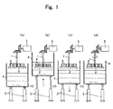
- Fig. 1 is a schematic process flow diagram showing an example of a dip spin coating method proposed in the present invention. The process is described step by step below: (a) Firstly, plural planar work pieces X are supported on approximately the outer peripheral edge portion of a turn table 2 which is rotatable around a center shaft 1 set in the vertical direction which is used as the axis of rotation, in such a manner that each of the work pieces X is set with the widest plane thereof (flat plane) placed approximately in parallel with the radial direction of the turn table 2 in approximately a ring-like arrangement.
- the work pieces X are immersion coated with paint by elevating a paint tank 4 using an air cylinder 3, and by immersing the turn table 2 having supported thereon the work pieces X into the paint tank 4.
- the turn table 2 is taken out of the fluid by lowering the paint tank 4 using the air cylinder 3.
- the paint adhered in excess to the flat plane of the work pieces X is centrifugally cut off by rotating the turn table 2 by using a motor 5 around the center shaft 1 that is used as the axis of rotation (preferably, the direction of rotation is reversed at least once).
- the amount of the paint adhered to the flat plane of the work pieces X can be freely controlled by adjusting the size of the turn table 2 or by controlling the rotation speed; accordingly, the film thickness of the coating film can be freely controlled.
- mesh plane is used as the plane of the turn table 2, such that the residual paint would not form a paint reservoir.
- Fig. 2 (a) shows an oblique view of a schematically drawn part of an example of a state in which plural planar work pieces X are supported on approximately the outer peripheral edge portion of a turn table 2 in approximately a ring-like arrangement, in which the flat plane of each of the work pieces X is set approximately in parallel with the radial direction.
- Fig. 2 (b) shows an upper planar view of the turn table 2 having supported thereon the work pieces X.
- the work pieces X are mounted on two supporting members 11 (preferably they are rod-like, and have a semicircle cross section) provided on the turn table 2.
- the work pieces X may be mounted directly on the turn table 2, and by employing such a mounting method, the mounting trace that is generated on the lower plane of the work pieces X can be minimized (see Fig. 2(c)).
- the planar work pieces X are supported in a state separated from each other by using spacers 12 provided in the vertical direction with respect to the supporting members 11.
- the spacers 12 also function as to prevent work pieces X from rolling.
- the interval between a spacer 12 and a neighboring spacer 12 is preferably wider than the thickness of the work piece X; because, if spacers 12 are constantly brought into contact with the both sides of the work pieces X, the contact trace becomes distinct.
- the cross section of the spacers 12 is preferably round, because the contact trace that is generated on the flat plane of the work pieces X by rotating the turn table 2 can be minimized.
- process step (d) in case the paint adhered in excess to the flat plane of the planar work pieces X is centrifugally cut off by rotating the turn table 2 around the center shaft 1 that is used as the axis of rotation by means of a motor 5, the work pieces X tend to fly out to the radial direction due to the centrifugal force, but the centrifugal fly-out regulation rods 13, which are fixed to the turn table 2 by the constitution omitted in the figure and arranged in the horizontal direction, are brought into contact with the outer side plane of the work pieces X and function as to prohibit work pieces X from flying out to the radial direction. Furthermore, the spacers 14 provided in the direction of the axis of rotation with respect to the centrifugal fly-out regulation rods 13 function as to regulate the movement of the work pieces X during their centrifugal cutting off of the paint.
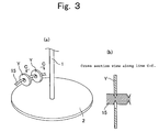
- Fig. 3(a) shows an oblique view of a schematically drawn part of an example of a state in which plural ring-shaped work pieces Y are supported on approximately the outer peripheral edge portion of a turn table 2 in approximately a ring-like arrangement, in which the flat plane of each of the work pieces Y is set approximately in parallel with the radial direction.
- the work pieces Y are supported to the turn table 2 by hanging the ring portion of the work pieces Y to horizontal hook members 15 fixed to the turn table 2 by the constitution omitted in the figure.
- the horizontal hook members 15 are preferably rod-like ones having a round cross section.
- the part of the horizontal hook members 15 onto which the work pieces Y are hung is cut, for example, in a V shape (see Fig. 3(b)).
- the hooking trace that is generated on the ring portion of the work pieces Y can be minimized.
- each of the thin type work pieces may be directly supported on the turn table as shown in Figs. 1 to 3; however, it is also possible to use a coating jig which is capable of setting each of the thin type work pieces apart from each other with the widest plane thereof being placed approximately in parallel with the radial direction of the turn table and in approximately a ring-like arrangement, in case of attaching it on approximately the outer peripheral edge portion of a turn table.
- Fig. 4 shows a schematically drawn oblique view of, in case of attaching on approximately the outer peripheral edge portion of a turn table, an example of a coating jig capable of setting each of the planar work pieces apart from each other with the flat plane thereof being placed approximately in parallel with the radial direction of the turn table and in approximately a ring-like arrangement.
- the coating jig Z at least comprises two supporting rods 21 with spacers 22, which are arranged in parallel with the horizontal direction and used for supporting plural planar work pieces X set apart from each other and in such a manner that the flat planes thereof are set approximately in parallel with the vertical direction, and centrifugal fly-out regulation rods 23 with spacers 24, which are arranged in parallel with the horizontal direction, are brought into contact with the outer side plane of the work pieces X and function as to prohibit work pieces X from flying out to the radial direction due to the centrifugal force in case the jig having the work pieces X set thereon is attached on approximately the outer peripheral edge portion of the turn table, and the turn table is rotated; however, it also comprises, on the upper side of the supporting rods 21, two rod-like members 25 with spacers 26 which are arranged in parallel with the supporting rods 21, in such a manner that the plural work pieces X may maintain the flat planes approximately in parallel with the vertical direction with appropriate intervals kept among them, and that space is kept between the
- Fig. 5 shows a schematic front view (a) and a cross section view along line D-D (b) of a coating jig Z having plural thin type work pieces X set thereon.
- the supporting rods 21 and rod-like members 25 each preferably have a circular cross section. In this manner, the mounting trace that is generated on the lower plane of the thin type work pieces X can be minimized. Furthermore, the centrifugal fly-out regulation rods 23 preferably have a circular cross section. In this manner, the contact trace that is generated on the outer side plane of the thin type work pieces X can be minimized. Also, the spacers 22, spacers 24, and spacers 26 each preferably have a circular cross section. In this manner, the contact trace that is generated on the flat plane of the thin type work pieces X can be minimized. Further, the supporting rods 21 as well as rod-like members 25 need not consist of two pieces each, and may consist of only one piece each.
- Fig. 6 is a schematic diagram showing a planar view of a part of an example of a state in which the coating jig Z having plural planar work pieces X set thereon is attached on approximately the outer peripheral edge portion of a turn table 2 using a known freely detachable attaching means.
- the work pieces X are immersion coated with a paint by immersing the turn table 2 having attached thereon the coating jig Z having the work pieces X set thereon into a paint tank 4, in accordance with the schematic process flow diagram shown in Fig. 1; i.e., by elevating the paint tank 4 using an air cylinder 2.
- the paint tank 4 is lowered by using the air cylinder 3 to take out the turn table 2 from the liquid.
- the dip spin coating is completed by rotating the turn table 2 by using a motor 5 around the center shaft 1 that is used as the axis of rotation, to thereby centrifugally cut off the paint adhered in excess to the flat plane of the work pieces X.
- the coating jig Z having the work pieces X still set thereon is detached from the turn table 2, and if desired, the work pieces X, which are still set on the coating jig Z, are subjected to a dry treatment (natural drying or hot drying) at an arbitrary place.
- the coating jig Z having the work pieces X still set thereon is reversed upside down and attached again on the turn table 2, such that the dip spin coating is carried out in a process similar to that above.
- the positions of the mounting trace and the contact trace generated in the second coating can be differed from those generated in the first coating, and the mounting trace and the contact trace generated in the first coating can be coated in the second coating; thus, a more uniform coating can be applied to the work pieces X.
- the coating jig Z having the work pieces X still set thereon is detached from the turn table 2, and if desired, the work pieces X, which are still set on the coating jig Z, are subjected to a dry treatment (natural drying or hot drying) at an arbitrary place; in this manner, an uniform coating film can be efficiently formed on a large number of work pieces without causing the fluctuation in the film thickness.
- a more uniform coating film can be formed by using an aqueous treating fluid having a viscosity of 300 cP to 600 cP.
- the aqueous treating fluid having such a viscosity is, as described above, such having its viscosity increased by adding a cellulose based thickener into an once prepared aqueous treating fluid (preferably, the thickener is added in such a manner that it accounts for 1 wt.% to 2 wt.% of the aqueous treating fluid).
- the heat treatment of the rare earth metal-based permanent magnet having the coating film of the aqueous treating fluid formed on the surface thereof is carried out at 250°C to 400°C.
- a part of the fine zinc particles contained in the aqueous treating fluid is properly diffused from the surface of the magnet body to the internal part during the process of forming the film, and a corrosion-resistant film containing fine zinc particles dispersed therein can be formed with high adhesive strength.
- the time duration of the heat treatment is preferably, for example, 10 minutes to 120 minutes.
- a further homogeneous corrosion-resistant film containing fine zinc particles dispersed therein can be formed by carrying out the heat treatment after once carrying out pre-drying at 100°C to 170°C on the rare earth metal-based permanent magnet having the aqueous treating fluid coating applied to the surface thereof.
- the corrosion-resistant film containing fine zinc particles dispersed therein is preferably formed in such a manner that the film thickness thereof falls in a range of 1 ⁇ m to 50 ⁇ m, and more preferably, in a range of 5 ⁇ m to 15 ⁇ m. If the film thickness should be less than 1 ⁇ m, it is feared that the properties necessary for a corrosion-resistant film containing fine zinc particles dispersed therein would not be sufficiently exhibited; on the other hand, if the film thickness should exceed 50 ⁇ m, it is feared that the effective volume as a rare earth metal-based permanent magnet would not be sufficiently acquired.
- fine inorganic particles may be additionally dispersed in the corrosion-resistant film containing fine zinc particles dispersed therein.
- fine inorganic particles there may be mentioned fine particles of metals that are potentially base similar to zinc, for instance, aluminum, tin, manganese, magnesium, titanium, nickel, and the like.
- the total weight of the fine zinc particles and the fine inorganic particles preferably accounts for 95 wt.% or less of the formed corrosion-resistant film.
- rare earth metal-based permanent magnets there can be mentioned, for instance, known R-Fe-B based permanent magnets represented by an Nd-Fe-B based permanent magnet, and R-Fe-N based permanent magnets represented by a Sm-Fe-N based permanent magnet, etc.
- R-Fe-B based permanent magnets are particularly preferred from the viewpoint of possessing high magnetic properties and of having excellent mass productivity as well as economical advantage.
- the rare earth metal-based permanent magnets may be sintered magnets or bonded magnets.
- the rare earth element (R) of the rare earth metal-based permanent magnets is preferably at least one selected from Nd, Pr, Dy, Ho, Tb, and Sm; or at least one selected from La, Ce, Gd, Er, Eu, Tm, Yb, Lu, and Y.
- one of the aforementioned rare earth metals is sufficient for use as R, but in practice, from the viewpoint of ease in availability and the like, it is possible to use a mixture of two or more (misch metal, didymium and the like).
- electrolytic iron, ferroboron, and Nd as R were blended to give the predetermined magnet composition, and after melting and casting, the resulting product was coarsely crushed and finely ground by a mechanical crushing method to obtain a fine powder having a granularity in a range of 3 ⁇ m to 10 ⁇ m.
- the fine powder thus obtained was shaped under a magnetic field of 10 kOe, sintered under argon atmosphere at 1100°C for 1 hour, and the resulting sinter was subjected to aging treatment at 600°C for 2 hours to obtain a magnetic body having a composition of 15Nd-7B-78Fe, from which a 36 mm ⁇ 32mm ⁇ 3 mm size planar sintered magnet test piece was cut out to be subjected to the following experiments.
- An aqueous solution having a pH value of 3 and containing 20 wt.% of ethyl silicate (where ethyl silicate was content was converted to SiO 2 content) as the starting raw material was prepared in the same manner as in Example 1.
- This aqueous solution thus prepared was mixed with an aqueous medium containing fine zinc particles and fine aluminum particles dispersed therein, which was prepared by adding an organic dispersing agent (Trademark: Solsperse S20000: produced by Avecia Limited), flaky fine zinc particles having an average major diameter of 20 ⁇ m (approximately 20 ⁇ m ⁇ 20 ⁇ m ⁇ 1 ⁇ m in size) , and fine granular aluminum particles having an average diameter of 3 ⁇ m in water, and after thoroughly stirring the resulting product, the pH value thereof was adjusted to 7 by using 1N sodium hydroxide.
- an organic dispersing agent Trademark: Solsperse S20000: produced by Avecia Limited
- flaky fine zinc particles having an average major diameter of 20 ⁇ m approximately 20 ⁇ m ⁇ 20 ⁇ m ⁇ 1 ⁇ m in size
- fine granular aluminum particles having an average diameter of 3 ⁇ m in water
- an aqueous treating fluid having a viscosity of 13 cP and containing ethyl silicate as the starting raw material, fine zinc particles, and fine aluminum particles at a total content of 70 wt. % (where ethyl silicate content was converted to SiO 2 content), in which ethyl silicate as the starting rawmaterial, fine zinc particles, fine aluminum particles, and the organic dispersing agent were contained at a mixing ratio of 9.9:60:30:0.1 (in weight ratio; where ethyl silicate content was converted to SiO 2 content).
- the resulting aqueous treating fluid was used to form a corrosion-resistant film containing fine zinc particles and fine aluminum particles dispersed therein at a fine zinc particles content of 60 wt.% and a fine aluminum particles content of 30 wt.% on the surface of the same test piece as in Example 1 in the same manner as in Example 1.
- the film thickness of the thus formed corrosion-resistant film containing fine zinc particles and fine aluminum particles dispersed therein was found to be about 10 ⁇ m (from observation of the cross section).
- Corrosion resistance test was performed in the same manner as in Example 1 on the thus produced ten test pieces having on the surface thereof the corrosion-resistant film containing fine zinc particles and fine aluminum particles dispersed therein, and found no change in appearance (no rust generation) on any of the test pieces after the test.
- An aqueous solution having a pH value of 3 and containing 20 wt.% of ethyl silicate (where ethyl silicate was content was converted to SiO 2 content) as the starting raw material was prepared in the same manner as in Example 1.
- This aqueous solution thus prepared was mixed with an aqueous medium containing fine zinc particles, fine aluminum particle, and fine tin particles dispersed therein, which was prepared by adding an organic dispersing agent (Trademark: Solsperse S20000: produced by Avecia Limited) , flaky fine zinc particles having an average major diameter of 20 ⁇ m (approximately 20 ⁇ m ⁇ 20 ⁇ m ⁇ 1 ⁇ m in size), fine granular aluminum particles having an average diameter of 3 ⁇ m, and fine granular tin particles having an average diameter of 3 ⁇ m in water, and after thoroughly stirring the resulting product, the pH value thereof was adjusted to 7 by using 1N sodium hydroxide.
- an organic dispersing agent Trademark: Solsperse S20000: produced by Avecia Limited
- an aqueous treating fluid having a viscosity of 18 cP and containing ethyl silicate as the starting raw material, fine zinc particles, fine aluminum particles, and fine tin particles at a total content of 70 wt.% (where ethyl silicate was content was converted to SiO 2 content), in which ethyl silicate as the starting raw material, fine zinc particles, fine aluminum particles, fine tin particles, and the organic dispersing agent were contained at a mixing ratio of 9.9:55:25:10:0.1 (in weight ratio; where ethyl silicate was content was converted to SiO 2 content).
- the resulting aqueous treating fluid was used to form a corrosion-resistant film containing fine zinc particles, fine aluminum particles and fine tin particles dispersed therein at a fine zinc particles content of 55 wt.%, a fine aluminum particles content of 25 wt.% and a fine tin particles content of 10 wt.% on the surface of the same test piece as in Example 1 in the same manner as in Example 1.
- the film thickness of the thus formed corrosion-resistant film containing fine zinc particles, fine aluminum particles, and fine tin particles dispersed therein was found to be about 10 ⁇ m (from observation of the cross section).
- Corrosion resistance test was performed in the same manner as in Example 1 on the thus produced ten test pieces having on the surface thereof the corrosion-resistant film containing fine zinc particles, fine aluminum particles, and fine tin particles dispersed therein, and found no change in appearance (no rust generation) on any of the test pieces after the test.
- An alloy powder consisting of particles having an average major diameter of 150 ⁇ m and having a composition of 12 atomic% Nd, 77 atomic% Fe, 6 atomic% B, and 5 atomic% Co was prepared by a rapid solidification process, and was kneaded with epoxy resin added at a concentration of 2 wt.%. The resulting mixture was compression molded under a pressure of 686 N/mm 2 , followed by curing at 150°C for 1 hour to obtain a ring-shaped bonded magnet test piece having an outer diameter of 30 mm, an inner diameter of 28 mm, and a length of 4 mm.
- the test piece was subjected to an experiment similar to that of Example 1 to form on the surface thereof a corrosion-resistant film containing fine zinc particles dispersed therein at a fine zinc particles content of 90 wt.%.
- the film thickness of the thus formed corrosion-resistant film containing fine zinc particles dispersed therein was found to be about 10 ⁇ m (from observation of the cross section).
- observation of the cross section in the vicinity of the surface of the test piece having on the surface thereof the corrosion-resistant film containing fine zinc particles dispersed therein was performed by using an EPMA (electron probe micro analyzer; EPM810 manufactured by Shimadzu Corp.).
- Fig. 7 is given the secondary electron image.
- Fig. 8 is given the X-ray image of zinc.
- Fig. 7 is given the secondary electron image.
- the viscosity of the aqueous treating fluid prepared in Example 1 was adjusted to 450 cP by adding hydroxyethyl cellulose as a thickener in such a manner that it accounts for 1 wt.% of the aqueous treating liquid.
- a large number of the same test pieces as in Example 1 subjected to ultrasonic washing (degreasing treatment) in ethanol and to natural drying for 15 minutes were set on a coating jig shown in Fig. 4, and the coating jig having the test pieces set thereon was attached on approximately the outer peripheral edge portion of the turn table as shown in Fig. 6 to perform a dip spin coating as shown in Fig.
- the coating jig having the test pieces still set thereon was taken out from the turn table and the test pieces still set on the coating jig were pre-dried in air at 130°C for 10 minutes; subsequently, a heat treatment was applied in air at 350°C for 30 minutes to the test pieces having the coating films of the aqueous treating fluid formed on the surface thereof.
- the coating jig having the test pieces still set thereon was reversed upside down, and was attached again on the turn table, such that a dip spin coating, a pre-drying, and a heat treatment were carried out in a process similar to that above to form a corrosion-resistant film containing fine zinc particles dispersed therein at a fine zinc particles content of 90 wt. % on the surface of the test pieces.
- the film thickness of the thus formed corrosion-resistant film containing fine zinc particles dispersed therein was found to be about 10 ⁇ m (from observation of the cross section).
- Corrosion resistance test was performed in the same manner as in Example 1 on the thus produced ten test pieces having on the surface thereof the corrosion-resistant film containing fine zinc particles dispersed therein, and found no change in appearance (no rust generation) on any of the test pieces after the test.
- the viscosity of the aqueous treating fluid prepared in Example 2 was adjusted to 440 cP by adding hydroxyethyl cellulose as a thickener in such a manner that it accounts for 1 wt.% of the aqueous treating liquid.
- a corrosion-resistant film containing fine zinc particles and fine aluminum particles dispersed therein at a fine zinc particles content of 60 wt.% and a fine aluminum particles content of 30 wt.% was formed in a similar manner as in Example 5 on the surface of the same test pieces as in Example 1 subjected to ultrasonic washing (degreasing treatment) in ethanol and to natural drying for 15 minutes.
- the film thickness of the thus formed corrosion-resistant film containing fine zinc particles and fine aluminum particles dispersed therein was found to be about 10 ⁇ m (from observation of the cross section). Corrosion resistance test was performed in the same manner as in Example 1 on the thus produced ten test pieces having on the surface thereof the corrosion-resistant film containing fine zinc particles and fine aluminum particles dispersed therein, and found no change in appearance (no rust generation) on any of the test pieces after the test.
- the viscosity of the aqueous treating fluid prepared in Example 3 was adjusted to 460 cP by adding hydroxyethyl cellulose as a thickener in such a manner that it accounts for 1 wt.% of the aqueous treating liquid.
- a corrosion-resistant film containing fine zinc particles, fine aluminum particles, and fine tin particles dispersed therein at a fine zinc particles content of 55 wt.%, a fine aluminum particles content of 25 wt.% and a fine tin particles content of 10 wt.% was formed in a similar manner as in Example 5 on the surface of the same test pieces as in Example 1 subjected to ultrasonic washing (degreasing treatment) in ethanol and to natural drying for 15 minutes.
- the film thickness of the thus formed corrosion-resistant film containing fine zinc particles, fine aluminum particles, and fine tin particles dispersed therein was found to be about 10 ⁇ m (from observation of the cross section).
- Corrosion resistance test was performed in the same manner as in Example 1 on the thus produced ten test pieces having on the surface thereof the corrosion-resistant film containing fine zinc particles, fine aluminum particles, and fine tin particles dispersed therein, and found no change in appearance (no rust generation) on any of the test pieces after the test.
- An aqueous solution having a pH value of 3 and containing 20 wt.% of ethyl silicate (where alkaline sodium silicate content was converted to SiO 2 content) as the starting raw material was prepared in the same manner as in Example 1.
- This aqueous solution thus prepared was mixed with an aqueous medium containing fine zinc particles, fine aluminum particles, fine tin particles, and fine alumina particles dispersed therein, which was prepared by adding an organic dispersing agent (Trademark: Solsperse S20000: produced by Avecia Limited), flaky fine zinc particles having an average major diameter of 20 ⁇ m (approximately 20 ⁇ m ⁇ 20 ⁇ m ⁇ 1 ⁇ m in size), fine granular aluminum particles having an average diameter of 3 ⁇ m, fine granular tin particles having an average diameter of 3 ⁇ m, and fine alumina particles having an average diameter of 1 ⁇ m in water; and after thoroughly stirring the resulting product, the pH value thereof was adjusted to 7 by using 1N sodium hydro
- an aqueous treating fluid having a viscosity of 16 cP and containing ethyl silicate as the starting raw material, fine zinc particles, fine aluminum particles, fine tin particles, and fine alumina particles at a total content of 70 wt. % (where alkaline sodium silicate content was converted to SiO 2 content), in which ethyl silicate as the starting raw material, fine zinc particles, fine aluminum particles, fine tin particles, fine alumina particles, and the organic dispersing agent were contained at a mixing ratio of 9.9:55:25:8:2:0.1 (in weight ratio; where alkaline sodium silicate content was converted to SiO 2 content).
- the viscosity of the aqueous treating fluid thus prepared was adjusted to 465 cP by adding hydroxyethyl cellulose as a thickener in such a manner that it accounts for 1 wt.% of the aqueous treating liquid.
- Example 5 a fine alumina particles content of 2 wt.% was formed in a similar manner as in Example 5 on the surface of the same test pieces as in Example 1 subjected to ultrasonic washing (degreasing treatment) in ethanol and to natural drying for 15 minutes.
- the film thickness of the thus formed corrosion-resistant film containing fine zinc particles, fine aluminum particles, fine tin particles, and fine alumina particles dispersed therein was found to be about 10 ⁇ m (from observation of the cross section).
- Corrosion resistance test was performed in the same manner as in Example 1 on the thus produced ten test pieces having on the surface thereof the corrosion-resistant film containing fine zinc particles, fine aluminum particles, fine tin particles, and fine alumina particles dispersed therein, and found no change in appearance (no rust generation) on any of the test pieces after the test.
- the viscosity of the treating solution prepared in Comparative Example 1 was adjusted to 420 cP by adding hydroxyethyl cellulose as a thickener in such a manner that it accounts for 1 wt.% of the treating solution.
- a corrosion-resistant film containing fine zinc particles dispersed therein at a fine zinc particles content of 90 wt.% was formed on the surface of the same test pieces as in Example 1 subjected to ultrasonic washing (degreasing treatment) in ethanol and to natural drying for 15 minutes, in a similar manner as in Example 5, except for setting the pre-drying condition and the heat treatment condition similar to those employed in Comparative Example 1.
- the film thickness of the thus formed corrosion-resistant film containing fine zinc particles dispersed therein was found to be about 10 ⁇ m (from observation of the cross section). Corrosion resistance test was performed in the same manner as in Example 1 on the thus produced ten test pieces having on the surface thereof the corrosion-resistant film containing fine zinc particles dispersed therein, and found that 6 test pieces showed change in appearance (rust generation) at time passage of 200 hours.
- the present invention has industrial applicability in the point that it provides a stable and simple method for producing a rare earth metal-based permanent magnet having on the surface thereof a corrosion-resistant film containing fine zinc particles dispersed therein, a corrosion-resistant rare earth metal-based permanent magnet produced by the method, a dip spin coating method being suitable for forming a coating film on thin type work pieces having various shapes, and a method for forming a coating film on a work piece.
Landscapes
- Chemical & Material Sciences (AREA)
- Engineering & Computer Science (AREA)
- Power Engineering (AREA)
- Materials Engineering (AREA)
- Chemical Kinetics & Catalysis (AREA)
- Mechanical Engineering (AREA)
- Metallurgy (AREA)
- Organic Chemistry (AREA)
- Inorganic Chemistry (AREA)
- Crystallography & Structural Chemistry (AREA)
- Environmental & Geological Engineering (AREA)
- Manufacturing & Machinery (AREA)
- Application Of Or Painting With Fluid Materials (AREA)
- Manufacturing Cores, Coils, And Magnets (AREA)
- Hard Magnetic Materials (AREA)
Applications Claiming Priority (5)
| Application Number | Priority Date | Filing Date | Title |
|---|---|---|---|
| JP2002348841 | 2002-11-29 | ||
| JP2002348841 | 2002-11-29 | ||
| JP2003319207 | 2003-09-11 | ||
| JP2003319207 | 2003-09-11 | ||
| PCT/JP2003/015268 WO2004051678A1 (fr) | 2002-11-29 | 2003-11-28 | Procede de fabrication d'un aimant permanent resistant a la corrosion a base de terres rares, aimant permanent resistant a la corrosion a base de terres rares, procede de revetement par immersion et rotation pour piece a usiner et procede pour former un film de revetement sur une piece a usiner |
Publications (3)
| Publication Number | Publication Date |
|---|---|
| EP1511046A1 true EP1511046A1 (fr) | 2005-03-02 |
| EP1511046A4 EP1511046A4 (fr) | 2009-04-22 |
| EP1511046B1 EP1511046B1 (fr) | 2015-05-20 |
Family
ID=32473663
Family Applications (1)
| Application Number | Title | Priority Date | Filing Date |
|---|---|---|---|
| EP20030812349 Expired - Lifetime EP1511046B1 (fr) | 2002-11-29 | 2003-11-28 | Procede de fabrication d'un aimant permanent resistant a la corrosion a base de terres rares, aimant permanent resistant a la corrosion a base de terres rares, procede de revetement par immersion et rotation pour piece a usiner et procede pour former un film de revetement sur une piece a usiner |
Country Status (5)
| Country | Link |
|---|---|
| US (2) | US7335392B2 (fr) |
| EP (1) | EP1511046B1 (fr) |
| KR (1) | KR101073326B1 (fr) |
| AU (1) | AU2003302524A1 (fr) |
| WO (1) | WO2004051678A1 (fr) |
Cited By (4)
| Publication number | Priority date | Publication date | Assignee | Title |
|---|---|---|---|---|
| WO2006003882A1 (fr) | 2004-06-30 | 2006-01-12 | Shin-Etsu Chemical Co., Ltd. | Aimants de terre rare résistants à la corrosion et procédé de production de ceux-ci |
| FR2906401A1 (fr) * | 2006-09-26 | 2008-03-28 | Commissariat Energie Atomique | Procede de depot d'une couche polymere sur une face non plane d'un support par trempage. |
| DE102005025469B4 (de) * | 2005-06-02 | 2009-08-27 | Vogt Electronic Components Gmbh | Verfahren und Vorrichtung zum Aufbringen einer Materialschicht auf elektrische Komponenten |
| EP2521141A4 (fr) * | 2009-12-28 | 2014-06-04 | Hitachi Metals Ltd | Aimant résistant à la corrosion et son procédé de fabrication |
Families Citing this family (15)
| Publication number | Priority date | Publication date | Assignee | Title |
|---|---|---|---|---|
| JP2005204480A (ja) * | 2004-01-19 | 2005-07-28 | Mitsubishi Electric Corp | 回転電機の回転子および回転電機 |
| EP1947657A1 (fr) * | 2005-08-08 | 2008-07-23 | Hitachi Metals, Ltd. | Aimant d alliage de terre rare sans liant et son procédé de fabrication |
| JP4706411B2 (ja) * | 2005-09-21 | 2011-06-22 | 住友電気工業株式会社 | 軟磁性材料、圧粉磁心、軟磁性材料の製造方法、および圧粉磁心の製造方法 |
| JP4783178B2 (ja) * | 2006-03-03 | 2011-09-28 | Jsr株式会社 | アルミニウム微粒子分散フィルムおよびその形成用組成物並びに形成方法 |
| US7781932B2 (en) | 2007-12-31 | 2010-08-24 | General Electric Company | Permanent magnet assembly and method of manufacturing same |
| WO2011108704A1 (fr) | 2010-03-04 | 2011-09-09 | Tdk株式会社 | Aimant de terre rare fritté et moteur |
| DE102012203898A1 (de) | 2012-03-13 | 2013-09-19 | Robert Bosch Gmbh | Permanentmagnet, sowie elektrische Maschine beinhaltend einen solchen, sowie Verfahren zum Herstellen der elektrischen Maschine |
| KR101368617B1 (ko) | 2013-04-16 | 2014-03-25 | 성림첨단산업(주) | 내식성 희토류 소결 영구자석 및 이를 위한 제조 방법 |
| JP6459758B2 (ja) * | 2015-04-28 | 2019-01-30 | 信越化学工業株式会社 | 希土類磁石の製造方法及び希土類化合物の塗布装置 |
| JP6365393B2 (ja) * | 2015-04-28 | 2018-08-01 | 信越化学工業株式会社 | 希土類磁石の製造方法及び希土類化合物の塗布装置 |
| KR101878228B1 (ko) * | 2018-04-06 | 2018-08-17 | 주식회사 메가젠임플란트 | 워터글라스 코팅 픽스츄어의 제조방법 |
| DE102018111331A1 (de) * | 2018-05-11 | 2019-11-14 | Ejot Gmbh & Co. Kg | Verfahren zur Beschichtung von Teilen in einem Tauch-Schleuderverfahren |
| CN113963932A (zh) * | 2021-10-21 | 2022-01-21 | 中钢天源股份有限公司 | 一种小尺寸r-t-b稀土永磁体的制备方法 |
| KR102405371B1 (ko) | 2021-12-13 | 2022-06-07 | 한국지질자원연구원 | 니켈도금층을 제거하는 방법 |
| CN115584496B (zh) * | 2022-10-25 | 2024-10-29 | 福建省金龙稀土股份有限公司 | 永磁体的表面处理方法、永磁体及其保护膜 |
Family Cites Families (27)
| Publication number | Priority date | Publication date | Assignee | Title |
|---|---|---|---|---|
| US2556744A (en) * | 1947-05-21 | 1951-06-12 | Raymond L Walrath | Painting apparatus |
| US3306602A (en) * | 1964-08-11 | 1967-02-28 | Bendix Corp | Work holder fixture |
| US3269633A (en) * | 1964-11-04 | 1966-08-30 | Sanders Associates Inc | Automatic spin soldering machine |
| US3917648A (en) * | 1971-01-18 | 1975-11-04 | G D Mcleod & Sons Inc | Galvanic coating compositions comprising polyol silcates and zinc dust |
| US3734337A (en) * | 1971-09-24 | 1973-05-22 | American Spin A Batch Co | Spin centrifuge baskets |
| JPS52151635A (en) | 1976-06-14 | 1977-12-16 | Dainippon Toryo Kk | Lusttproof coating composition |
| JPS5964671A (ja) | 1982-10-05 | 1984-04-12 | Kansai Paint Co Ltd | 無機質塗膜の形成方法 |
| JPS60179180A (ja) * | 1984-02-24 | 1985-09-13 | Kansai Paint Co Ltd | 防食被覆方法 |
| JPS6213470A (ja) | 1985-07-11 | 1987-01-22 | Kansai Paint Co Ltd | 防錆被覆組成物 |
| US4988755A (en) * | 1987-12-14 | 1991-01-29 | The B. F. Goodrich Company | Passivated rare earth magnet or magnetic material compositions |
| JPH01197385A (ja) * | 1988-02-03 | 1989-08-09 | Matsushita Electric Ind Co Ltd | 基板保持体 |
| US4870814A (en) * | 1988-04-29 | 1989-10-03 | Orscheln Co. | Process for manufacturing corrosion resistant cable |
| JPH0313486A (ja) | 1989-06-09 | 1991-01-22 | Hitachi Ltd | エレベータの扉制御装置 |
| US4933025A (en) * | 1989-10-02 | 1990-06-12 | General Motors Corporation | Method for enhancing magnetic properties of rare earth permanent magnets |
| JPH0664762U (ja) * | 1991-03-11 | 1994-09-13 | マルイ鍍金工業株式会社 | 塗装処理装置と乾燥処理装置 |
| US5167701A (en) * | 1992-05-22 | 1992-12-01 | Savin Roland R | Zinc-rich coating composition with inorganic binder |
| JPH0664762A (ja) | 1992-08-17 | 1994-03-08 | Ricoh Co Ltd | 給紙カセット |
| EP0855049B1 (fr) * | 1996-08-01 | 2005-11-09 | Loctite (Ireland) Limited | Procede de formation d'une monocouche de particules et produits realises selon ce procede |
| GB9803970D0 (en) * | 1998-02-26 | 1998-04-22 | Univ Birmingham | Method of applying a corrosion-resistant coating |
| JP3719483B2 (ja) | 1998-11-30 | 2005-11-24 | 日亜化学工業株式会社 | 希土類系磁性粉末およびその表面処理方法 |
| JP3966631B2 (ja) * | 1998-12-15 | 2007-08-29 | 信越化学工業株式会社 | 希土類・鉄・ボロン系永久磁石の製造方法 |
| JP3519069B2 (ja) | 1999-01-27 | 2004-04-12 | 住友特殊金属株式会社 | 希土類系焼結磁石 |
| JP3278647B2 (ja) * | 1999-01-27 | 2002-04-30 | 住友特殊金属株式会社 | 希土類系ボンド磁石 |
| JP3719492B2 (ja) | 1999-02-26 | 2005-11-24 | 日亜化学工業株式会社 | 希土類系磁性粉末及びその表面処理方法並びにそれを用いた希土類ボンド磁石 |
| JP3159693B1 (ja) * | 1999-08-30 | 2001-04-23 | 住友特殊金属株式会社 | 耐食性被膜を有する希土類系永久磁石の製造方法 |
| JP3781095B2 (ja) * | 2000-02-15 | 2006-05-31 | 信越化学工業株式会社 | 耐食性希土類磁石の製造方法 |
| JP2001295071A (ja) | 2000-04-06 | 2001-10-26 | Kansai Paint Co Ltd | 鋼板前処理方法 |
-
2003
- 2003-11-28 AU AU2003302524A patent/AU2003302524A1/en not_active Abandoned
- 2003-11-28 WO PCT/JP2003/015268 patent/WO2004051678A1/fr not_active Ceased
- 2003-11-28 EP EP20030812349 patent/EP1511046B1/fr not_active Expired - Lifetime
- 2003-11-28 US US10/511,598 patent/US7335392B2/en not_active Expired - Lifetime
- 2003-11-28 KR KR1020047018573A patent/KR101073326B1/ko not_active Expired - Lifetime
-
2007
- 2007-12-27 US US12/005,391 patent/US20080124567A1/en not_active Abandoned
Cited By (5)
| Publication number | Priority date | Publication date | Assignee | Title |
|---|---|---|---|---|
| WO2006003882A1 (fr) | 2004-06-30 | 2006-01-12 | Shin-Etsu Chemical Co., Ltd. | Aimants de terre rare résistants à la corrosion et procédé de production de ceux-ci |
| EP1734539A4 (fr) * | 2004-06-30 | 2007-06-06 | Shinetsu Chemical Co | Aimants de terre rare résistants à la corrosion et procédé de production de ceux-ci |
| DE102005025469B4 (de) * | 2005-06-02 | 2009-08-27 | Vogt Electronic Components Gmbh | Verfahren und Vorrichtung zum Aufbringen einer Materialschicht auf elektrische Komponenten |
| FR2906401A1 (fr) * | 2006-09-26 | 2008-03-28 | Commissariat Energie Atomique | Procede de depot d'une couche polymere sur une face non plane d'un support par trempage. |
| EP2521141A4 (fr) * | 2009-12-28 | 2014-06-04 | Hitachi Metals Ltd | Aimant résistant à la corrosion et son procédé de fabrication |
Also Published As
| Publication number | Publication date |
|---|---|
| AU2003302524A1 (en) | 2004-06-23 |
| US7335392B2 (en) | 2008-02-26 |
| US20050233068A1 (en) | 2005-10-20 |
| EP1511046A4 (fr) | 2009-04-22 |
| KR20050083572A (ko) | 2005-08-26 |
| KR101073326B1 (ko) | 2011-10-12 |
| EP1511046B1 (fr) | 2015-05-20 |
| US20080124567A1 (en) | 2008-05-29 |
| WO2004051678A1 (fr) | 2004-06-17 |
Similar Documents
| Publication | Publication Date | Title |
|---|---|---|
| US20080124567A1 (en) | Corrosion-resistant rare earth metal-based permanent magnet | |
| CN1618108A (zh) | 稀土类烧结磁体及其制造方法 | |
| JP2021087010A (ja) | Nd−Fe−B系焼結永久磁性体の希土類元素拡散処理方法 | |
| KR100607297B1 (ko) | 내식성 피막을 가지는 Fe-B-R계 영구자석의 제조방법 | |
| JP4285218B2 (ja) | 耐食性希土類系永久磁石の製造方法および耐食性希土類系永久磁石 | |
| CN100361239C (zh) | 抗腐蚀稀土金属基永磁体的制造方法、抗腐蚀稀土金属基永磁体 | |
| EP1028438B1 (fr) | Procede de fabrication d'aimants a liaison r-fe-b presentant une haute resistance a la corrosion | |
| EP1453069B1 (fr) | Aimant permanent a base de terres rares comportant un revetement anticorrosion et procede de production de ce dernier | |
| JP2002075767A (ja) | 耐食性被膜を有する希土類系永久磁石およびその製造方法 | |
| JP3187396B2 (ja) | 耐食性皮膜を有するFe−B−R系永久磁石の製造方法 | |
| JP2004200387A (ja) | 耐食性永久磁石およびその製造方法 | |
| JP3236815B2 (ja) | 高耐食性R−Fe−B系ボンド磁石とその製造方法 | |
| JP3236813B2 (ja) | 高耐食性R−Fe−B系ボンド磁石とその製造方法 | |
| JP2004266093A (ja) | 希土類系ボンド磁石の製造方法 | |
| EP0984464B1 (fr) | Procédé de fabrication d'un aimant permanent à base de R-Fe-B, pourvu d'un film résistant à la corrosion | |
| CN1131530C (zh) | 具有耐腐蚀膜的Fe-B-R基永磁体的制造工艺 | |
| JP2003100536A (ja) | ボンド磁石空孔部の封孔処理方法 | |
| JPWO1999023676A1 (ja) | 高耐食性R−Fe−B系ボンド磁石の製造方法 | |
| JPH11238641A (ja) | 高耐食性R−Fe−B系ボンド磁石とその製造方法 | |
| JP2004356615A (ja) | 耐酸化性希土類系磁石粉末およびその製造方法 | |
| JPH10154611A (ja) | 絶縁性のすぐれた耐食性永久磁石及びその製造方法 | |
| JPS6377102A (ja) | 耐食性のすぐれた希土類磁石及びその製造方法 | |
| JPH0462903A (ja) | 永久磁石及びその製造方法 | |
| JPS63166975A (ja) | 耐酸化性のすぐれた永久磁石の製造方法 |
Legal Events
| Date | Code | Title | Description |
|---|---|---|---|
| PUAI | Public reference made under article 153(3) epc to a published international application that has entered the european phase |
Free format text: ORIGINAL CODE: 0009012 |
|
| 17P | Request for examination filed |
Effective date: 20041109 |
|
| AK | Designated contracting states |
Kind code of ref document: A1 Designated state(s): AT BE BG CH CY CZ DE DK EE ES FI FR GB GR HU IE IT LI LU MC NL PT RO SE SI SK TR |
|
| AX | Request for extension of the european patent |
Extension state: AL LT LV MK |
|
| DAX | Request for extension of the european patent (deleted) | ||
| RBV | Designated contracting states (corrected) |
Designated state(s): DE FI FR GB NL |
|
| RAP1 | Party data changed (applicant data changed or rights of an application transferred) |
Owner name: HITACHI METALS, LTD. |
|
| A4 | Supplementary search report drawn up and despatched |
Effective date: 20090324 |
|
| RIC1 | Information provided on ipc code assigned before grant |
Ipc: H01F 1/059 20060101ALI20090318BHEP Ipc: H01F 1/057 20060101ALI20090318BHEP Ipc: H01F 41/02 20060101AFI20040623BHEP Ipc: B05C 11/08 20060101ALI20090318BHEP Ipc: C23C 26/00 20060101ALI20090318BHEP Ipc: B05C 13/02 20060101ALI20090318BHEP |
|
| 17Q | First examination report despatched |
Effective date: 20090921 |
|
| GRAP | Despatch of communication of intention to grant a patent |
Free format text: ORIGINAL CODE: EPIDOSNIGR1 |
|
| INTG | Intention to grant announced |
Effective date: 20141208 |
|
| GRAS | Grant fee paid |
Free format text: ORIGINAL CODE: EPIDOSNIGR3 |
|
| GRAA | (expected) grant |
Free format text: ORIGINAL CODE: 0009210 |
|
| RIN1 | Information on inventor provided before grant (corrected) |
Inventor name: OTANI, TOMOIKU Inventor name: YOSHIMURA, KOHSHI |
|
| AK | Designated contracting states |
Kind code of ref document: B1 Designated state(s): DE FI FR GB NL |
|
| REG | Reference to a national code |
Ref country code: GB Ref legal event code: FG4D |
|
| RIN2 | Information on inventor provided after grant (corrected) |
Inventor name: OTANI, TOMOIKU Inventor name: YOSHIMURA, KOHSHI |
|
| REG | Reference to a national code |
Ref country code: DE Ref legal event code: R096 Ref document number: 60347643 Country of ref document: DE |
|
| REG | Reference to a national code |
Ref country code: NL Ref legal event code: MP Effective date: 20150520 |
|
| PG25 | Lapsed in a contracting state [announced via postgrant information from national office to epo] |
Ref country code: FI Free format text: LAPSE BECAUSE OF FAILURE TO SUBMIT A TRANSLATION OF THE DESCRIPTION OR TO PAY THE FEE WITHIN THE PRESCRIBED TIME-LIMIT Effective date: 20150520 |
|
| REG | Reference to a national code |
Ref country code: DE Ref legal event code: R097 Ref document number: 60347643 Country of ref document: DE |
|
| PLBE | No opposition filed within time limit |
Free format text: ORIGINAL CODE: 0009261 |
|
| STAA | Information on the status of an ep patent application or granted ep patent |
Free format text: STATUS: NO OPPOSITION FILED WITHIN TIME LIMIT |
|
| 26N | No opposition filed |
Effective date: 20160223 |
|
| GBPC | Gb: european patent ceased through non-payment of renewal fee |
Effective date: 20151128 |
|
| REG | Reference to a national code |
Ref country code: FR Ref legal event code: ST Effective date: 20160729 |
|
| PG25 | Lapsed in a contracting state [announced via postgrant information from national office to epo] |
Ref country code: GB Free format text: LAPSE BECAUSE OF NON-PAYMENT OF DUE FEES Effective date: 20151128 |
|
| PG25 | Lapsed in a contracting state [announced via postgrant information from national office to epo] |
Ref country code: FR Free format text: LAPSE BECAUSE OF NON-PAYMENT OF DUE FEES Effective date: 20151130 |
|
| PG25 | Lapsed in a contracting state [announced via postgrant information from national office to epo] |
Ref country code: NL Free format text: LAPSE BECAUSE OF FAILURE TO SUBMIT A TRANSLATION OF THE DESCRIPTION OR TO PAY THE FEE WITHIN THE PRESCRIBED TIME-LIMIT Effective date: 20150520 |
|
| PGFP | Annual fee paid to national office [announced via postgrant information from national office to epo] |
Ref country code: DE Payment date: 20220621 Year of fee payment: 20 |
|
| REG | Reference to a national code |
Ref country code: DE Ref legal event code: R071 Ref document number: 60347643 Country of ref document: DE |