EP1512062B1 - Ameliorations apportees ou liees au refroidissement de composants electriques et/ou electroniques, specifiquement de materiel informatique - Google Patents
Ameliorations apportees ou liees au refroidissement de composants electriques et/ou electroniques, specifiquement de materiel informatique Download PDFInfo
- Publication number
- EP1512062B1 EP1512062B1 EP03713084A EP03713084A EP1512062B1 EP 1512062 B1 EP1512062 B1 EP 1512062B1 EP 03713084 A EP03713084 A EP 03713084A EP 03713084 A EP03713084 A EP 03713084A EP 1512062 B1 EP1512062 B1 EP 1512062B1
- Authority
- EP
- European Patent Office
- Prior art keywords
- fan
- cooling
- electrical
- combination
- electronic component
- Prior art date
- Legal status (The legal status is an assumption and is not a legal conclusion. Google has not performed a legal analysis and makes no representation as to the accuracy of the status listed.)
- Expired - Lifetime
Links
Images


Classifications
-
- H—ELECTRICITY
- H05—ELECTRIC TECHNIQUES NOT OTHERWISE PROVIDED FOR
- H05K—PRINTED CIRCUITS; CASINGS OR CONSTRUCTIONAL DETAILS OF ELECTRIC APPARATUS; MANUFACTURE OF ASSEMBLAGES OF ELECTRICAL COMPONENTS
- H05K7/00—Constructional details common to different types of electric apparatus
- H05K7/20—Modifications to facilitate cooling, ventilating, or heating
- H05K7/20709—Modifications to facilitate cooling, ventilating, or heating for server racks or cabinets; for data centers, e.g. 19-inch computer racks
- H05K7/20718—Forced ventilation of a gaseous coolant
- H05K7/20727—Forced ventilation of a gaseous coolant within server blades for removing heat from heat source
-
- G—PHYSICS
- G06—COMPUTING OR CALCULATING; COUNTING
- G06F—ELECTRIC DIGITAL DATA PROCESSING
- G06F1/00—Details not covered by groups G06F3/00 - G06F13/00 and G06F21/00
- G06F1/16—Constructional details or arrangements
- G06F1/20—Cooling means
Definitions
- the invention relates to a improvements in or relating to cooling of electrical and/or electronic components, and computer equipment in particular.
- the invention relates specifically to a fan arranged in a computer casing for drawing in cooling air for electrical and/or electronic components, said fan comprising a housing with at least one suction opening, at least one outlet opening and at least one wheel arranged between the suction opening and the outlet opening for rotation on an axis and bearing a number of blades, the suction opening being arranged in a base plate of the housing that is substantially perpendicular to the rotation axis of the blade wheel, and the blades in the wheel being placed and embodied such that the flow of the cooling air generated thereby has a radial or centrifugal component.
- a fan is known from US-A-3 829 250 .
- Fans for cooling computer equipment have been embodied heretofore solely as radial fans, wherein the suction opening, the outlet opening and the blade wheel are arranged coaxially in a tubular housing.
- Such an axial fan has a relatively low efficiency, whereby a relatively large fan has to be used to achieve a high cooling capacity, which moreover has to develop a considerable rotation speed.
- the noise production of axial fans is hereby relatively high.
- US-A-3 829 250 discloses a fan for cooling PCBs in a computer.
- This known fan comprises a rotating disc arranged in a cylindrical housing and carrying a plurality of blades. The free ends of the blades are connected by a ring.
- This fan has a central suction opening at a first side of the housing. Cooling air is initially blown in radial direction by the blade wheel, but is subsequently deflected by the cylindrical sidewall of the fan housing and finally exits the fan in axial direction.
- the invention now has for its object to propose improvements in the field of cooling electrical and/or electronic components, whereby Lhe above described problems do not occur, or do so to a lesser extent.
- this is accomplished in a fan of the above described type in that the housing has an inner side wall that is oriented substantially parallel to the rotation axis of the blade wheel and that moves in a spiral shape away from the blade wheel in the rotation direction of said wheel, the outlet opening being formed in said side wall, whereby cooling air drawn in through the suction opening substantially in the direction of the rotation axis is blown out substantially transversely of the direction of said axis.
- a structurally simple embodiment of this fan is characterized in that the blades are formed by elongate, profiled slats arranged distributed on a rotatable ring and extending substantially parallel to the rotation axis of the ring.
- the suction opening arranged in the base plate can advantageously debouch within a periphery defined by the slats
- the housing can further include an upper plate on which a motor driving the blade wheel is mounted. This motor can also be advantageously arranged within a periphery defined by the slats.
- the fan may be used for withdrawing air from the computer casing after it has flowed along the electrical and/or electronic components.
- outlet opening is connected with an electrical and/or electronic component to be cooled. In that case the fan would blow the cooling air into the computer casing.
- a compact and efficient embodiment of the fan is obtained when the dimension of the blade wheel in the axial direction is substantially equal to its diameter.
- the invention further relates to a combination of a fan as described above and a connecting part for connecting an opening of the fan to an electrical or electronic component.
- the connecting part of this combination comprises a frame with fixing means for the fan and means for connecting the frame to the electrical or electronic component.
- the connecting means comprise a rapid-action coupling. Assembly operations are hereby simplified.
- This rapid-action coupling preferably comprises at least two hook parts engaging round the electrical or electronic component and tensioning means connected thereto.
- a coupling can be effected in rapid and reliable manner by arranging the hook parts behind a protruding portion of the component(s) for cooling and subsequently tensioning the tensioning parts.
- a cooling block enclosed between the connecting part and the component for cooling is pressed uniformly onto the component.
- a tensioning part which is easy to operate comprises a spring-loaded lever.
- the frame is preferably dimensioned such that it can be placed in close-fitting manner round at least a part of the cooling block. This ensures an airtight connection.
- the cooling block is provided with at least one wall running substantially transversely of the cooling fins for deflecting of the flow thereby. This deflecting ot the flow ensures that the cooling air must cover a longer path through the cooling block, whereby more time is available for heat transfer between the cooling ribs and the air brushing therealong and better cooling is achieved as a consequence.
- a structurally simple embodiment is obtained when the deflecting wall is received in a cut-away portion running through adjacent cooling fins. So as to limit the number of different parts, the deflecting wall advantageously forms part of a connecting part. Different functions can thus be integrated into one component.
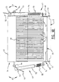
- a casing 1 for electrical and/or electronic components such as motherboards with processors 2 (fig. 3), graphic cards, a power supply 3 and storage units, for instance a number of hard disk stations 4 and CD-ROM and/or DVD players and/or writers 5, comprises a frame 6, a front wall 7, two side walls 8, a rear wall 9, an upper wall 10 and a base 11 (fig. 1).
- Walls 7-10 enclose the frame 6 practically on all sides and form a substantially airtight casing.
- the frame 6 is manufactured from metal, while the front wall 7, upper wall 10, rear wall 9 and side walls 8 are formed integrally (fig. 10) from plastic which is optionally covered on the inside with a layer of sound-damping material, for instance felt.
- These walls 7-10 are mutually connected by fold lines 17 and have on the inside protruding strips 18 which in the assembled situation of casing 1 engage in profiles 19 of frame 6 (fig. 8).
- the front wall 7 and side walls 8 are provided along their lower edge with clamping strips 20, 21 which are snapped round a lower edge 22 of frame 6 to fix the walls 7-10 to frame 6.
- the base 11 is left open and thus forms a suction opening 12, while a number of outlet openings 13 is formed in upper wall 10 of casing 1.
- a number of outlet openings 13 is formed in upper wall 10 of casing 1.
- cooling air is drawn into casing 1 (arrows S) and blown out of it again (arrows B).
- fans 14 in the shown embodiment four in number, which are placed between suction openings 12 and outlet openings 13.
- the fans 14 are arranged close to outlet openings 13.
- Fans 14 hereby draw the cooling air through casing 1 instead of blowing it therethrough.
- Outlet openings 13 are here arranged in upper wall 10. Owing to this arrangement an airflow is generated from bottom to top through casing 1 which enhances the natural tendency of warm air to rise.
- Casing 1 is intended to produce a considerably higher cooling capacity than conventional computer housings, inter alia by increasing the amount of cooling air which flows through casing 1.
- the base 11 which defines the suction opening 12 is covered with filter material 15.
- This filter material 15 is in the form of a mat accommodated releasably in a drawer 16, which is in turn received slidably in an opening 23 close to the bottom edge of front wall 7 so that filter material 15 can be readily replaced or cleaned.
- openings 24 are Further formed in front wall 7 through which access is obtained to DVD players 5.
- openings 24 are not is use, for instance because fewer than the maximum number of components are accommodated in casing 1, they are closed in airtight manner with snap-on covers (not shown).
- Sealing material for instance felt, is moreover arranged around openings 24 in order to prevent as far as possible air being drawn in through openings 24. Similar sealing material can also be arranged along the opening 23 for the filter drawer 16.
- a relatively large opening 25 through which the necessary cabling can be connected in simple manner to motherboards 2, graphic card(s) and power supply 3. These are specifically power supply cables and connecting cables to peripheral equipment such as a monitor, a keyboard, a printer and the like.
- peripheral equipment such as a monitor, a keyboard, a printer and the like.
- a sleeve 26 tapering toward the outside which is fastened using velcro to the peripheral edge 27 of opening 25, and which has a relatively narrow opening 28, which is likewise closed using velcro in close-fitting manner around the cables fed therethrough.
- the guiding of the cooling airflows through casing 1 is optimized further in the shown embodiment in that the different components 2-5 for cooling are connected to their associated fan(s) 14 via cooling hoses 29 and/or ducts 30. This prevents warm air coming from components 2-5 being able to circulate freely through casing 1.
- fans 14 are each accommodated in their own closed compartment 31 on the top side of casing 1.
- the separating walls 32 between compartments 31 can here also be covered with a layer of absorbent material, for instance felt, in order to limit the noise production as far as possible.
- another layer of sound-damping material 33 is further arranged above compartments 31 in order to limit as far as possible the egress of sound from casing 1 into the surrounding space.
- a sound-damping mat use could also be made of for instance a labyrinth through which the cooling air would have to leave the casing 1.
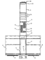
- this connecting part 34 is dimensioned such that it connects close-fittingly onto a cooling block 35 connected to component 2 (fig. 6, 7) in order to transfer the heat generated thereby as efficiently as possible to the flow-by cooling air.
- the cooling block 35 comprises a base 36 which is connected to the component for cooling, here therefore to the motherboard with processor 2, and a number of parallel cooling fins 37 protruding from base 36.
- the base and the cooling fins are here formed integrally from a material with a high heat conductivity, for instance copper or an alloy thereof.
- two deflecting walls 38 are formed transversely of cooling fins 37, which walls extend from the free edges of cooling fins 37 over a part of the height of cooling fins 37 in the direction of base 36.
- the cooling air is hereby forced to follow a winding path (arrows C) between cooling fins 37, whereby the flow speed is decreased and contact time increased.
- Deflecting walls 38 are received in cut-away portions 39 formed in cooling fins 37.
- cooling block 35 is also provided with two deflecting walls 75 extending from the base 36 over the whole height of cooling fins 37. These walls 75 serve to prevent the cooling air flows which develop from both sides of cooling block 35 from meeting each other in the middle of the block. This would result in large swirls and associated pressure losses. Walls 75 deflect these cooling air flows in controlled manner so that they flow away almost transversely of base 36 and, after leaving cooling block 35, provide a uniform flow pattern. Between walls 75 is defined a space 76 through which cooling air can also be drawn in. If necessary, secondary cooling fins 77 running transversely of cooling fins 37 can further be placed in this space 76. A single central deflecting wall 75 could also be used instead of two walls 75 with an intermediate space 76.
- the deflecting walls 38 are formed by two parallel side wall parts 40 of the frame 41 of connecting part 34.
- This frame 41 further comprises two transverse walls 42, the distance between which is the same as the width of cooling block 35, and an upper plate 43.
- Formed in upper plate 43 is an opening 44 for drawing off cooling air to the cooling hose 29 or directly to fan 14.
- Upper plate 43 also has means 78 for fixing thereto either a mouthpiece 45 of cooling hose 29 (fig. 8) or a base plate 46 of fan 14 (fig. 9).
- These fixing means 78 here take the form of four holes for receiving screws or bolts.
- connecting part 34 is provided with means 47 for connecting frame 41 to the component 2-5 for cooling or the cooling block 35 optionally mounted thereon. So as to be able to effect this connection in rapid and simple manner the connecting means 47 here take the form of a rapid-action coupling.
- this rapid-action coupling is formed by two hook parts 48 and tensioning parts 49 connected to each of the hook parts 48.
- Each hook part 48 consists of a plate or strip with a number of openings 50 formed therein which can be pushed round protruding parts 51 of the component for cooling.
- Each of the hook parts 48 is connected to frame 41 via tensioning part 49.
- This tensioning part 49 comprises a lever 52 which is pivotable on a shaft 54 mounted on frame 41.
- Lever 52 has a transverse carrier 53 to which are fixed outer tubes 73 of two telescopic legs.
- the corresponding inner tubes 74 are fixed to the corresponding hook part 48.
- the telescopic legs are urged to their shown extended position by compression springs 55.
- Each lever 52 is pivotable as according to arrow P between the position shown on the right in fig. 6B, in which springs 55 are not under pressure, and a position rotated through about 180° on the left in fig. 6B, in which lever 53 rests against frame 41 and springs 55 are tensioned and pull the connecting part 34 taut against cooling block 35.
- hook parts 48 each have two protrusions 50 and the motherboard is provided with openings 51.
- the transverse carrier 53 of each lever 52 is further connected to hook part 48 by means of two draw springs 55.
- a cooling hose 29 and connecting part 34 For guiding of the air coming from storage units 4, 5, use is not made in the shown embodiment of a cooling hose 29 and connecting part 34 but of a duct 30 which extends as a kind of "chimney" along the storage units 4, 5 (fig. 3).
- This duct 30 is formed here by a lower part 56 which runs along hard disk stations 4 and an upper part 57 connecting thereto which runs along the CD-ROM or DVD stations 5.
- Openings 58 are arranged in duct 30 at the location of points where storage units 4, 5 can be connected thereto (fig. 4). When no storage unit 4, 5 for cooling is present at the relevant location, these openings 58 can be closed in airtight manner by covers 59 so that the cooling air is drawn only along the storage units 4, 5 actually installed in casing 1.
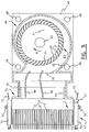
- each fan 14 is provided for this purpose with a housing 60 with a suction opening 61, an outlet opening 62 and a wheel 63 arranged therebetween which is rotatable on a shaft 64 and which bears a number of blades 65 (fig. 9).
- Housing 60 is formed by a base plate 46 in which the suction opening 61 is arranged, a spiral-shaped side wall 66 having therein the outlet opening 62, and an upper plate 67.
- Base plate 46 is provided with means 68 for fixing the fan 14 to a connecting part 34, to an end part 69 of a cooling hose 29 or to a bottom 70 of a compartment 31.
- Connecting means 68 here take the form of a number of holes for receiving screws, bolts or other fastening elements.
- Blades 65 extend parallel to rotation shaft 64 of wheel 63 and are formed by elongate profiled slats which are arranged distributed between two rotatable rings 71. Slats 65 lie outside suction opening 61.
- Rotation shaft 64 is mounted in upper plate 67 and blade wheel 63 is driven by a motor 72, for instance an electric motor, which is mounted around the shaft 64 on upper plate 67.
- the fan 14 shown and described above is in an arrangement in which it draws in air, it can also be used to blow cooling air while still retaining the advantages resulting from its configuration.
- the suction opening 61 is connected to suction opening 12 in casing 1, while outlet opening 62 is fixed to connecting part 34 via a coupling 79 (fig. 11).
- This connecting part 34 is in turn fixed in the known manner to a component for cooling and the cooling block 35 arranged thereon.
- two baffles 80 are also arranged in coupling 79.
- the invention thus provides a casing in which electrical and/or electronic components can be optimally cooled with relatively simple means. This makes it possible to accommodate a large number of high-power components, such as are for instance found in a server, in a casing of compact dimensions. Measurements on a prototype have shown that, even at very high processor load, the temperature of a motherboard 2 in the casing 1 according to the invention becomes no higher than about 25°C, while the temperature of the processor itself varies between 40 and 55°C. An identical motherboard in a casing with the same dimensions and lay-out, but without the improved cooling according to the invention, reaches a temperature at the same load of about 55 to 60°C. The temperature of the processor rises here to almost 85°C.
Landscapes
- Engineering & Computer Science (AREA)
- Theoretical Computer Science (AREA)
- General Engineering & Computer Science (AREA)
- Physics & Mathematics (AREA)
- Human Computer Interaction (AREA)
- General Physics & Mathematics (AREA)
- Microelectronics & Electronic Packaging (AREA)
- Thermal Sciences (AREA)
- Computer Hardware Design (AREA)
- Cooling Or The Like Of Electrical Apparatus (AREA)
- Polyurethanes Or Polyureas (AREA)
- Compositions Of Macromolecular Compounds (AREA)
- Macromonomer-Based Addition Polymer (AREA)
- Epoxy Compounds (AREA)
- Organic Low-Molecular-Weight Compounds And Preparation Thereof (AREA)
Claims (16)
- Ventilateur (14) agencé dans un boîtier d'ordinateur (1) pour faire entrer de l'air de refroidissement destiné à des composants électriques et/ou électroniques (2-5), ledit ventilateur (14) comportant un carter (60) ayant au moins une ouverture d'aspiration (61), au moins une ouverture de sortie (62) et au moins une roue (63) agencée entre l'ouverture d'aspiration (61) et l'ouverture de sortie (62) pour tourner sur un axe (64) et supporter plusieurs aubes (65), l'ouverture d'aspiration (61) étant agencée dans une plaque de base (46) du carter (60) qui est sensiblement perpendiculaire à l'axe de rotation (64) de la roue à aubes (63), et les aubes (65) de la roue (63) étant placées et constituées de sorte que l'écoulement de l'air de refroidissement produit par celles-ci a une composante radiale ou centrifuge, caractérisé en ce que le carter (60) a une paroi latérale intérieure (66) qui est orientée sensiblement parallèlement à l'axe de rotation (64) de la roue à aubes (63) et qui s'éloigne de la roue à aubes (63) selon une forme de spirale dans la direction de rotation de ladite roue (63), l'ouverture de sortie (62) étant formée dans ladite paroi latérale (66), de sorte que l'air de refroidissement entré à travers l'ouverture d'aspiration sensiblement dans la direction de l'axe de rotation (64) est soufflé à l'extérieur sensiblement transversalement par rapport à la direction dudit axe (64).
- Ventilateur (14) selon la revendication 1, caractérisé en ce que les aubes (65) sont formées par des lamelles profilées allongées agencées de manière répartie sur un anneau rotatif (71) et s'étendant sensiblement parallèlement à l'axe de rotation (64) de l'anneau (71).
- Ventilateur (14) selon la revendication 2, caractérisé en ce que l'ouverture d'aspiration (61) agencée dans la plaque de base (46) débouche dans une périphérie définie par les lamelles, et en ce que le carter (60) comporte de plus une plaque supérieure (67) sur laquelle est monté un moteur (72) entraînant la roue à aubes (63).
- Ventilateur (14) selon la revendication 3, caractérisé en ce que le moteur (72) est agencé dans une périphérie définie par les lamelles.
- Ventilateur (14) selon l'une quelconque des revendications précédentes, caractérisé en ce que la plaque de base (46) comporte des moyens (68) pour fixer le ventilateur (14) par exemple sur une partie de liaison (34) ou sur un tuyau de refroidissement (29).
- Ventilateur (14) selon l'une quelconque des revendications 1 à 4, caractérisé en ce que l'ouverture de sortie (62) est reliée à un composant électrique et/ou électronique (2 à 5) à refroidir.
- Ventilateur (14) selon l'une quelconque des revendications précédentes, caractérisé en ce que la dimension de la roue à aubes (63) dans la direction axiale est sensiblement égale à son diamètre.
- Combinaison d'un ventilateur (14) selon l'une quelconque des revendications précédentes et d'une partie de liaison (34) pour relier une ouverture (61, 62) dudit ventilateur (14) à un composant électrique ou électronique (2 à 5).
- Combinaison selon la revendication 8, caractérisée en ce que ladite partie de liaison (34) comporte un châssis (41) ayant des moyens de fixation (78, 79) du ventilateur (14) et des moyens (47) pour relier le châssis (41) au composant électrique ou électronique (2 à 5).
- Combinaison selon la revendication 9, caractérisée en ce que les moyens de liaison (47) sont constitués d'un accouplement à action rapide.
- Combinaison selon la revendication 10, caractérisée en ce que l'accouplement à action rapide comporte au moins deux parties de crochet (48) venant en prise autour du composant électrique ou électronique (2 à 5) et des parties de mise sous traction (49) reliées à celles-ci.
- Combinaison selon la revendication 11, caractérisée en ce que la partie de mise sous traction (49) comprend d'un levier chargé par ressort (52).
- Combinaison selon l'une quelconque des revendications 9 à 12, caractérisée en ce qu'un bloc de refroidissement (35) est relié au composant électrique ou électronique (2 à 5), ledit bloc de refroidissement (35) comportant une base (36) pour liaison au composant électrique ou électronique et plusieurs ailettes de refroidissement sensiblement parallèles (37) faisant saillie à partir de celle-ci, le châssis (41) étant dimensionné de telle sorte qu'il peut être placé de manière serrée autour d'au moins une partie dudit bloc de refroidissement (35).
- Combinaison selon la revendication 13, caractérisée en ce que ledit bloc de refroidissement (35) comporte au moins une paroi (38) s'étendant sensiblement transversalement par rapport aux ailettes de refroidissement (37) pour dévier ainsi l'écoulement.
- Combinaison selon la revendication 14, caractérisée en ce que la paroi de déviation (38) est reçue dans une partie découpée (39) s'étendant à travers des ailettes de refroidissement adjacentes (37).
- Combinaison selon la revendication 15, caractérisée en ce que la paroi de déviation (38) forme une partie de ladite partie de liaison (34).
Priority Applications (2)
| Application Number | Priority Date | Filing Date | Title |
|---|---|---|---|
| SI200331072T SI1512062T1 (sl) | 2002-05-31 | 2003-03-11 | Hlajenje elektricnih in/ali elektronskih komponent, se posebej racunalniske opreme |
| CY20081100026T CY1108858T1 (el) | 2002-05-31 | 2008-01-09 | Ψυξη ηλεκτρικων και/ή ηλεκτρονικων εξαρτηματων, συγκεκριμενα εξοπλισμου υπολογιστων |
Applications Claiming Priority (3)
| Application Number | Priority Date | Filing Date | Title |
|---|---|---|---|
| NL1020727 | 2002-05-31 | ||
| NL1020727 | 2002-05-31 | ||
| PCT/NL2003/000184 WO2003102746A2 (fr) | 2002-05-31 | 2003-03-11 | Ameliorations apportees ou liees au refroidissement de composants electriques et/ou electroniques, specifiquement de materiel informatique |
Publications (2)
| Publication Number | Publication Date |
|---|---|
| EP1512062A2 EP1512062A2 (fr) | 2005-03-09 |
| EP1512062B1 true EP1512062B1 (fr) | 2007-10-10 |
Family
ID=29707799
Family Applications (1)
| Application Number | Title | Priority Date | Filing Date |
|---|---|---|---|
| EP03713084A Expired - Lifetime EP1512062B1 (fr) | 2002-05-31 | 2003-03-11 | Ameliorations apportees ou liees au refroidissement de composants electriques et/ou electroniques, specifiquement de materiel informatique |
Country Status (13)
| Country | Link |
|---|---|
| US (1) | US7813129B2 (fr) |
| EP (1) | EP1512062B1 (fr) |
| JP (1) | JP2005536869A (fr) |
| KR (1) | KR100986948B1 (fr) |
| AT (1) | ATE375542T1 (fr) |
| AU (1) | AU2003221263A1 (fr) |
| CY (1) | CY1108858T1 (fr) |
| DE (1) | DE60316801T2 (fr) |
| DK (1) | DK1512062T3 (fr) |
| ES (1) | ES2295568T3 (fr) |
| PT (1) | PT1512062E (fr) |
| WO (1) | WO2003102746A2 (fr) |
| ZA (1) | ZA200409696B (fr) |
Cited By (1)
| Publication number | Priority date | Publication date | Assignee | Title |
|---|---|---|---|---|
| CN111787719A (zh) * | 2020-07-14 | 2020-10-16 | 湖北皓天智通科技有限公司 | 一种便于拆装的机房一体化机柜 |
Families Citing this family (43)
| Publication number | Priority date | Publication date | Assignee | Title |
|---|---|---|---|---|
| SE527918C2 (sv) * | 2004-12-22 | 2006-07-11 | Dometic Sweden Ab | Apparatlåda för dator samt dator innefattande en sådan apparatlåda |
| JP4493611B2 (ja) | 2005-12-13 | 2010-06-30 | 富士通株式会社 | 電子機器 |
| US7379299B2 (en) * | 2006-03-17 | 2008-05-27 | Kell Systems | Noiseproofed and ventilated enclosure for electronics equipment |
| US7379298B2 (en) * | 2006-03-17 | 2008-05-27 | Kell Systems | Noise proofed ventilated air intake chamber for electronics equipment enclosure |
| US8016927B2 (en) * | 2007-04-11 | 2011-09-13 | Hewlett-Packard Development Company, L.P. | Computing device filter system |
| WO2009142644A1 (fr) * | 2008-05-23 | 2009-11-26 | Hewlett-Packard Development Company, L.P. | Châssis d'ordinateur |
| US9426903B1 (en) * | 2008-06-27 | 2016-08-23 | Amazon Technologies, Inc. | Cooling air stack for computer equipment |
| US20100175554A1 (en) * | 2009-01-15 | 2010-07-15 | Dell Products L.P. | Cooling system with debris filtering |
| CN102135117A (zh) * | 2010-01-23 | 2011-07-27 | 富准精密工业(深圳)有限公司 | 离心风扇 |
| US7952857B1 (en) * | 2010-02-22 | 2011-05-31 | Motley Gregory O | Arc-resistant switchgear enclosure with ambient air ventilation system |
| US8335081B2 (en) | 2010-07-16 | 2012-12-18 | Rockwell Automation Technologies, Inc. | Heat sink cooling arrangement for multiple power electronic circuits |
| US8325478B2 (en) * | 2010-07-16 | 2012-12-04 | Rockwell Automation Technologies, Inc. | Cooling duct attachment and sealing for a motor drive |
| US8325479B2 (en) * | 2010-07-16 | 2012-12-04 | Rockwell Automation Technologies, Inc. | Motor drive cooling duct system and method |
| US8184434B2 (en) * | 2010-08-19 | 2012-05-22 | M & A Technology Inc. | Video/audio computer display processor |
| JP5348623B2 (ja) | 2010-09-10 | 2013-11-20 | 株式会社安川電機 | 電子機器装置 |
| US8593760B2 (en) | 2011-04-28 | 2013-11-26 | Entrotech, Inc. | Hard disk drives with electrical connectors comprising a flexible circuit extending through an opening in the base and related methods |
| US9466335B2 (en) | 2011-04-28 | 2016-10-11 | Entrotech, Inc. | Hermetic hard disk drives comprising integrally molded filters and related methods |
| US8837080B2 (en) | 2011-04-28 | 2014-09-16 | Entrotech, Inc. | Hard disk drives with composite housings and related methods |
| US8427787B2 (en) | 2011-04-28 | 2013-04-23 | Entrotech, Inc. | Hard disk drives with improved exiting regions for electrical connectors and related methods |
| US8599514B2 (en) | 2011-04-28 | 2013-12-03 | Entrotech, Inc. | Stabilization of components within hard disk drives and related methods |
| US8533934B2 (en) | 2011-04-28 | 2013-09-17 | Entrotech, Inc. | Method of assembling a hard disk drive |
| US9190115B2 (en) | 2011-04-28 | 2015-11-17 | Entrotech, Inc. | Method of assembling a disk drive |
| JP5861509B2 (ja) * | 2012-03-13 | 2016-02-16 | 富士電機株式会社 | 半導体電力変換装置の排気ファン支持構造 |
| US9125302B2 (en) * | 2012-04-23 | 2015-09-01 | Emerson Network Power, Energy Systems, North America, Inc. | Electronic equipment enclosures and methods related thereto |
| DE102014101611A1 (de) * | 2014-02-10 | 2015-08-13 | Fujitsu Technology Solutions Intellectual Property Gmbh | Kühlanordnung für eine partikelfreie Kühlung eines Computersystems |
| EP3134898A4 (fr) | 2014-04-22 | 2017-12-13 | Entrotech, Inc. | Lecteurs de disque dur ré-usinables, joints d'étanchéité de couvercle , pour ces derniers et procédés connexes |
| US10002645B2 (en) | 2014-06-09 | 2018-06-19 | Entrotech, Inc. | Laminate-wrapped hard disk drives and related methods |
| US10993353B2 (en) * | 2014-09-29 | 2021-04-27 | Hewlett Packard Enterprise Development Lp | Fan controlled ambient air cooling of equipment in a controlled airflow environment |
| CN105697396A (zh) * | 2014-11-25 | 2016-06-22 | 台达电子工业股份有限公司 | 离心式风扇 |
| US10718342B2 (en) | 2014-11-25 | 2020-07-21 | Delta Electronics, Inc. | Centrifugal fan comprising a sidewall and plurality of air deflectors forming a plurality of airflow entry tunnels to sequentially expand a flow channel outwardly in a radial direction |
| CN105992486A (zh) * | 2015-01-28 | 2016-10-05 | 鸿富锦精密工业(武汉)有限公司 | 散热模组 |
| US9601161B2 (en) | 2015-04-15 | 2017-03-21 | entroteech, inc. | Metallically sealed, wrapped hard disk drives and related methods |
| US9832912B2 (en) | 2015-05-07 | 2017-11-28 | Dhk Storage, Llc | Computer server heat regulation utilizing integrated precision air flow |
| JP6538607B2 (ja) | 2016-03-31 | 2019-07-03 | 株式会社ソニー・インタラクティブエンタテインメント | 電子機器 |
| US10433464B1 (en) * | 2016-06-06 | 2019-10-01 | ZT Group Int'l, Inc. | Air duct for cooling a rear-mounted switch in a rack |
| US10388327B2 (en) * | 2017-02-28 | 2019-08-20 | Western Digital Technologies, Inc. | Fan noise attenuation at hard disk drive in rack-mount |
| JP7181443B2 (ja) * | 2018-02-14 | 2022-12-01 | 日本電産サンキョー株式会社 | 冷却装置 |
| US11152283B2 (en) * | 2018-11-15 | 2021-10-19 | Hewlett Packard Enterprise Development Lp | Rack and row-scale cooling |
| US11015608B2 (en) | 2018-12-10 | 2021-05-25 | Hewlett Packard Enterprise Development Lp | Axial flow pump with reduced height dimension |
| TWI768882B (zh) * | 2021-05-07 | 2022-06-21 | 緯穎科技服務股份有限公司 | 具有伸縮裝置的伺服器機箱、及具有伸縮裝置的伺服器 |
| CN114321582B (zh) * | 2021-11-30 | 2024-04-02 | 中建八局第一建设有限公司 | 一种节能环保的建筑机电设备安装固定装置 |
| DE102022117314A1 (de) * | 2022-07-12 | 2024-01-18 | Andreas Seibold | Vorrichtung zum austausch von wärmeenergie mit der umgebungsluft |
| CN117812903B (zh) * | 2024-02-28 | 2024-05-17 | 英莱德科技股份公司 | 一种智慧政务自助服务终端装置 |
Family Cites Families (42)
| Publication number | Priority date | Publication date | Assignee | Title |
|---|---|---|---|---|
| US1884898A (en) * | 1930-05-07 | 1932-10-25 | Joseph Porzel | Air circulating and temperature changing unit |
| US3829250A (en) | 1971-09-22 | 1974-08-13 | Torin Corp | Blower assembly |
| US4838762A (en) * | 1988-04-11 | 1989-06-13 | General Motors Corporation | Fan body and rotor cup assembly |
| US4944654A (en) * | 1989-05-15 | 1990-07-31 | Carrier Corporation | Split scroll for centrifugal blower |
| GB2241118A (en) * | 1990-02-15 | 1991-08-21 | Ibm | Electrical apparatus with forced air cooling |
| US5107398A (en) * | 1990-05-30 | 1992-04-21 | Digital Equipment Corporation | Cooling system for computers |
| JPH051829A (ja) * | 1991-06-24 | 1993-01-08 | Brother Ind Ltd | 移動式空気調和装置 |
| US5158741A (en) * | 1991-08-16 | 1992-10-27 | General Electric Company | Passive cooling system for top entry liquid metal cooled nuclear reactors |
| JP3293104B2 (ja) * | 1992-02-20 | 2002-06-17 | 株式会社デンソー | 多翼送風機 |
| JP3069819B2 (ja) | 1992-05-28 | 2000-07-24 | 富士通株式会社 | ヒートシンク並びに該ヒートシンクに用いるヒートシンク取付具及びヒートシンクを用いた可搬型電子装置 |
| JPH0786779A (ja) * | 1993-06-22 | 1995-03-31 | Mitsubishi Cable Ind Ltd | 密閉筐体の熱交換装置 |
| JPH07269490A (ja) * | 1994-03-31 | 1995-10-17 | Nippon Densan Corp | 送風機 |
| US5409352A (en) | 1994-04-18 | 1995-04-25 | Lin; Mike | CPU heat dissipating device |
| GB2293487B (en) * | 1994-09-21 | 1998-08-12 | Hewlett Packard Co | Method and apparatus for attaching a heat sink and a fan to an intergrated circuit package |
| JP3784333B2 (ja) * | 1995-05-31 | 2006-06-07 | 山洋電気株式会社 | 電子部品冷却装置 |
| US5566377A (en) * | 1995-07-10 | 1996-10-15 | Lee; Richard | Heat dissipating apparatus |
| US5588803A (en) * | 1995-12-01 | 1996-12-31 | General Motors Corporation | Centrifugal impeller with simplified manufacture |
| JPH09172113A (ja) | 1995-12-18 | 1997-06-30 | Nec Corp | 半導体装置用ヒートシンク |
| US6011299A (en) * | 1996-07-24 | 2000-01-04 | Digital Equipment Corporation | Apparatus to minimize integrated circuit heatsink E.M.I. radiation |
| US5664624A (en) | 1996-11-04 | 1997-09-09 | Chin-Fu Tsai | Sloped wall type heat radiating member for chip |
| GB2322962B (en) * | 1997-03-03 | 2001-10-10 | Motor One Electronics Inc | Heat dissipating fan/integrated circuit assemblies |
| JP4269092B2 (ja) * | 1997-05-21 | 2009-05-27 | Toto株式会社 | 多翼遠心ファン |
| US5876278A (en) * | 1997-05-29 | 1999-03-02 | Cheng; Henry | Cooling device |
| US6141213A (en) | 1997-06-24 | 2000-10-31 | Sun Microsystems, Inc. | Computer with high airflow and low acoustic noise |
| US5927947A (en) * | 1997-12-08 | 1999-07-27 | Ford Motor Company | Dynamically balanced centrifugal fan |
| JP2911441B1 (ja) * | 1998-04-03 | 1999-06-23 | 伊藤 さとみ | ヒートパイプ及びその製造方法とそれを用いた放熱構造 |
| PL355228A1 (en) * | 1999-06-01 | 2004-04-05 | Volker Dalheimer | Housing system for housing electronic components, especially a flat desktop pc or multimedia housing |
| US6695038B2 (en) * | 1999-09-02 | 2004-02-24 | Advanced Rotary Systems, Llc | Heat exchanger type fan |
| JP2001111277A (ja) * | 1999-10-05 | 2001-04-20 | Toshiba Corp | 遠心ファンとそれを用いた電子機器 |
| JP2001153090A (ja) * | 1999-12-01 | 2001-06-05 | Toshiba Home Technology Corp | 冷却ファンモータ |
| JP2002048085A (ja) * | 2000-07-28 | 2002-02-15 | Mitsubishi Electric Corp | 多連型多翼送風機用羽根車、多連型多翼送風機および空気調和機 |
| US20020062947A1 (en) * | 2000-11-07 | 2002-05-30 | O'connor John F. | Centrifugal impeller |
| TW590169U (en) * | 2000-12-27 | 2004-06-01 | Delta Electronics Inc | Embedded centrifugal cooling device |
| DE20107242U1 (de) * | 2001-04-26 | 2001-07-12 | Joker GmbH, 82256 Fürstenfeldbruck | Filterlüfter |
| JP2003008272A (ja) * | 2001-06-25 | 2003-01-10 | Nec Corp | 防塵用フイルタ搭載電子装置 |
| US6664673B2 (en) * | 2001-08-27 | 2003-12-16 | Advanced Rotary Systems Llc | Cooler for electronic devices |
| US7071587B2 (en) * | 2001-09-07 | 2006-07-04 | Rotys Inc. | Integrated cooler for electronic devices |
| US6884033B2 (en) * | 2003-09-29 | 2005-04-26 | Cheng Home Electronics Co., Ltd. | Volute inlet of fan |
| US6980434B2 (en) * | 2003-10-22 | 2005-12-27 | Chieh Ou Yang | Computer fan assembly mechanism having filtering and sterilizing functions |
| US7108482B2 (en) * | 2004-01-23 | 2006-09-19 | Robert Bosch Gmbh | Centrifugal blower |
| TWI257837B (en) * | 2004-06-11 | 2006-07-01 | Quanta Comp Inc | Dissipation module with noise reduction function |
| TWM309846U (en) * | 2006-10-12 | 2007-04-11 | Quanta Comp Inc | Heat dissipation device |
-
2003
- 2003-03-11 EP EP03713084A patent/EP1512062B1/fr not_active Expired - Lifetime
- 2003-03-11 KR KR1020047019531A patent/KR100986948B1/ko not_active Expired - Fee Related
- 2003-03-11 DK DK03713084T patent/DK1512062T3/da active
- 2003-03-11 JP JP2004509765A patent/JP2005536869A/ja active Pending
- 2003-03-11 DE DE60316801T patent/DE60316801T2/de not_active Expired - Lifetime
- 2003-03-11 PT PT03713084T patent/PT1512062E/pt unknown
- 2003-03-11 AT AT03713084T patent/ATE375542T1/de active
- 2003-03-11 ES ES03713084T patent/ES2295568T3/es not_active Expired - Lifetime
- 2003-03-11 AU AU2003221263A patent/AU2003221263A1/en not_active Abandoned
- 2003-03-11 WO PCT/NL2003/000184 patent/WO2003102746A2/fr not_active Ceased
- 2003-03-11 US US10/516,097 patent/US7813129B2/en not_active Expired - Fee Related
-
2004
- 2004-11-30 ZA ZA200409696A patent/ZA200409696B/en unknown
-
2008
- 2008-01-09 CY CY20081100026T patent/CY1108858T1/el unknown
Cited By (1)
| Publication number | Priority date | Publication date | Assignee | Title |
|---|---|---|---|---|
| CN111787719A (zh) * | 2020-07-14 | 2020-10-16 | 湖北皓天智通科技有限公司 | 一种便于拆装的机房一体化机柜 |
Also Published As
| Publication number | Publication date |
|---|---|
| AU2003221263A1 (en) | 2003-12-19 |
| AU2003221263A8 (en) | 2003-12-19 |
| US7813129B2 (en) | 2010-10-12 |
| KR20050029125A (ko) | 2005-03-24 |
| WO2003102746A2 (fr) | 2003-12-11 |
| KR100986948B1 (ko) | 2010-10-12 |
| WO2003102746A3 (fr) | 2004-04-29 |
| EP1512062A2 (fr) | 2005-03-09 |
| PT1512062E (pt) | 2008-01-15 |
| CY1108858T1 (el) | 2014-07-02 |
| ATE375542T1 (de) | 2007-10-15 |
| ES2295568T3 (es) | 2008-04-16 |
| DK1512062T3 (da) | 2008-02-04 |
| WO2003102746B1 (fr) | 2004-06-03 |
| JP2005536869A (ja) | 2005-12-02 |
| DE60316801T2 (de) | 2008-07-17 |
| DE60316801D1 (de) | 2007-11-22 |
| ZA200409696B (en) | 2005-09-29 |
| US20060120045A1 (en) | 2006-06-08 |
Similar Documents
| Publication | Publication Date | Title |
|---|---|---|
| EP1512062B1 (fr) | Ameliorations apportees ou liees au refroidissement de composants electriques et/ou electroniques, specifiquement de materiel informatique | |
| US6179561B1 (en) | Fan wheel structures | |
| US6333852B1 (en) | CPU heat dissipation device with special fins | |
| US12291078B2 (en) | Air conditioning unit | |
| US20090324403A1 (en) | Impeller with Hybrid Blades for Blowers | |
| US11527936B2 (en) | Heat-dissipation frame assembly | |
| KR101311399B1 (ko) | 팬 | |
| WO2021228620A1 (fr) | Unité de climatisation | |
| ES2297084T3 (es) | Soplador electrico y aspiradora provista del mismo. | |
| US20110056659A1 (en) | Heat Dissipating Module | |
| CN106930214B (zh) | 吹风机 | |
| US20070211439A1 (en) | Electronic apparatus having drawer trays | |
| US7236360B2 (en) | Tower PC configuration | |
| US6939105B2 (en) | Airflow guiding structure for a heat-dissipating fan | |
| EP1755124A2 (fr) | Appareil de refroidissement électronique | |
| JP3072039B2 (ja) | 外部記憶装置の冷却構造 | |
| CN216364938U (zh) | 洗地机的滚刷机构及地刷装置 | |
| NL1030237C2 (nl) | Verbeteringen aan of met betrekking tot de koeling van elektrische en/of elektronische componenten, in het bijzonder computerapparatuur. | |
| CN210780410U (zh) | 风冷式电机 | |
| CN212672121U (zh) | 无叶风扇 | |
| CN115405541A (zh) | 一种吹风机 | |
| US8672650B2 (en) | Cooling fan | |
| NL1023197C2 (nl) | Verbeteringen aan of met betrekking tot de koeling van elektrische en/of elektronische componenten, in het bijzonder computerapparatuur. | |
| CN223152310U (zh) | 高效散热的空气悬浮离心风机 | |
| CN112484277A (zh) | 风道组件及具有其的空调器 |
Legal Events
| Date | Code | Title | Description |
|---|---|---|---|
| PUAI | Public reference made under article 153(3) epc to a published international application that has entered the european phase |
Free format text: ORIGINAL CODE: 0009012 |
|
| 17P | Request for examination filed |
Effective date: 20041223 |
|
| AK | Designated contracting states |
Kind code of ref document: A2 Designated state(s): AT BE BG CH CY CZ DE DK EE ES FI FR GB GR HU IE IT LI LU MC NL PT RO SE SI SK TR |
|
| AX | Request for extension of the european patent |
Extension state: AL LT LV MK |
|
| RIC1 | Information provided on ipc code assigned before grant |
Ipc: 7G 06F 1/20 A Ipc: 7F 04D 29/58 B Ipc: 7F 04D 29/60 B |
|
| DAX | Request for extension of the european patent (deleted) | ||
| 17Q | First examination report despatched |
Effective date: 20060706 |
|
| GRAP | Despatch of communication of intention to grant a patent |
Free format text: ORIGINAL CODE: EPIDOSNIGR1 |
|
| GRAS | Grant fee paid |
Free format text: ORIGINAL CODE: EPIDOSNIGR3 |
|
| GRAA | (expected) grant |
Free format text: ORIGINAL CODE: 0009210 |
|
| AK | Designated contracting states |
Kind code of ref document: B1 Designated state(s): AT BE BG CH CY CZ DE DK EE ES FI FR GB GR HU IE IT LI LU MC NL PT RO SE SI SK TR |
|
| REG | Reference to a national code |
Ref country code: GB Ref legal event code: FG4D |
|
| REG | Reference to a national code |
Ref country code: CH Ref legal event code: EP |
|
| REG | Reference to a national code |
Ref country code: IE Ref legal event code: FG4D |
|
| REF | Corresponds to: |
Ref document number: 60316801 Country of ref document: DE Date of ref document: 20071122 Kind code of ref document: P |
|
| REG | Reference to a national code |
Ref country code: RO Ref legal event code: EPE |
|
| REG | Reference to a national code |
Ref country code: PT Ref legal event code: SC4A Free format text: AVAILABILITY OF NATIONAL TRANSLATION Effective date: 20080104 |
|
| REG | Reference to a national code |
Ref country code: SE Ref legal event code: TRGR |
|
| REG | Reference to a national code |
Ref country code: CH Ref legal event code: NV Representative=s name: ARNOLD & SIEDSMA AG |
|
| REG | Reference to a national code |
Ref country code: DK Ref legal event code: T3 |
|
| REG | Reference to a national code |
Ref country code: EE Ref legal event code: FG4A Ref document number: E001713 Country of ref document: EE Effective date: 20080103 |
|
| REG | Reference to a national code |
Ref country code: GR Ref legal event code: EP Ref document number: 20080400016 Country of ref document: GR |
|
| REG | Reference to a national code |
Ref country code: ES Ref legal event code: FG2A Ref document number: 2295568 Country of ref document: ES Kind code of ref document: T3 |
|
| REG | Reference to a national code |
Ref country code: HU Ref legal event code: AG4A Ref document number: E002765 Country of ref document: HU |
|
| ET | Fr: translation filed | ||
| PLBE | No opposition filed within time limit |
Free format text: ORIGINAL CODE: 0009261 |
|
| STAA | Information on the status of an ep patent application or granted ep patent |
Free format text: STATUS: NO OPPOSITION FILED WITHIN TIME LIMIT |
|
| 26N | No opposition filed |
Effective date: 20080711 |
|
| PGFP | Annual fee paid to national office [announced via postgrant information from national office to epo] |
Ref country code: IT Payment date: 20100330 Year of fee payment: 8 |
|
| PGFP | Annual fee paid to national office [announced via postgrant information from national office to epo] |
Ref country code: CY Payment date: 20100906 Year of fee payment: 8 |
|
| PGFP | Annual fee paid to national office [announced via postgrant information from national office to epo] |
Ref country code: LU Payment date: 20110930 Year of fee payment: 9 Ref country code: BG Payment date: 20110930 Year of fee payment: 9 Ref country code: MC Payment date: 20110930 Year of fee payment: 9 |
|
| PGFP | Annual fee paid to national office [announced via postgrant information from national office to epo] |
Ref country code: AT Payment date: 20110930 Year of fee payment: 9 Ref country code: CZ Payment date: 20110907 Year of fee payment: 9 Ref country code: SK Payment date: 20110907 Year of fee payment: 9 Ref country code: TR Payment date: 20110908 Year of fee payment: 9 Ref country code: SE Payment date: 20110930 Year of fee payment: 9 Ref country code: RO Payment date: 20110902 Year of fee payment: 9 Ref country code: GR Payment date: 20110930 Year of fee payment: 9 Ref country code: HU Payment date: 20110907 Year of fee payment: 9 Ref country code: PT Payment date: 20110901 Year of fee payment: 9 Ref country code: EE Payment date: 20110930 Year of fee payment: 9 Ref country code: FI Payment date: 20110930 Year of fee payment: 9 |
|
| PGFP | Annual fee paid to national office [announced via postgrant information from national office to epo] |
Ref country code: BE Payment date: 20111003 Year of fee payment: 9 Ref country code: CH Payment date: 20110930 Year of fee payment: 9 Ref country code: ES Payment date: 20110930 Year of fee payment: 9 Ref country code: DK Payment date: 20110930 Year of fee payment: 9 |
|
| PGFP | Annual fee paid to national office [announced via postgrant information from national office to epo] |
Ref country code: SI Payment date: 20110906 Year of fee payment: 10 |
|
| REG | Reference to a national code |
Ref country code: PT Ref legal event code: MM4A Free format text: LAPSE DUE TO NON-PAYMENT OF FEES Effective date: 20120911 |
|
| BERE | Be: lapsed |
Owner name: J. VAN DER WERFF HOLDING B.V. Effective date: 20120331 |
|
| REG | Reference to a national code |
Ref country code: SE Ref legal event code: EUG |
|
| PG25 | Lapsed in a contracting state [announced via postgrant information from national office to epo] |
Ref country code: MC Free format text: LAPSE BECAUSE OF NON-PAYMENT OF DUE FEES Effective date: 20120331 Ref country code: CZ Free format text: LAPSE BECAUSE OF NON-PAYMENT OF DUE FEES Effective date: 20120311 Ref country code: FI Free format text: LAPSE BECAUSE OF NON-PAYMENT OF DUE FEES Effective date: 20120311 Ref country code: SE Free format text: LAPSE BECAUSE OF NON-PAYMENT OF DUE FEES Effective date: 20120312 Ref country code: CY Free format text: LAPSE BECAUSE OF NON-PAYMENT OF DUE FEES Effective date: 20120311 |
|
| PGFP | Annual fee paid to national office [announced via postgrant information from national office to epo] |
Ref country code: GB Payment date: 20120928 Year of fee payment: 10 Ref country code: IE Payment date: 20120829 Year of fee payment: 10 |
|
| REG | Reference to a national code |
Ref country code: CH Ref legal event code: PL |
|
| REG | Reference to a national code |
Ref country code: DK Ref legal event code: EBP |
|
| PG25 | Lapsed in a contracting state [announced via postgrant information from national office to epo] |
Ref country code: PT Free format text: LAPSE BECAUSE OF NON-PAYMENT OF DUE FEES Effective date: 20120911 |
|
| REG | Reference to a national code |
Ref country code: SK Ref legal event code: MM4A Ref document number: E 2914 Country of ref document: SK Effective date: 20120311 |
|
| REG | Reference to a national code |
Ref country code: GR Ref legal event code: ML Ref document number: 20080400016 Country of ref document: GR Effective date: 20121008 |
|
| REG | Reference to a national code |
Ref country code: AT Ref legal event code: MM01 Ref document number: 375542 Country of ref document: AT Kind code of ref document: T Effective date: 20120311 |
|
| REG | Reference to a national code |
Ref country code: EE Ref legal event code: MM4A Ref document number: E001713 Country of ref document: EE Effective date: 20120331 |
|
| PGFP | Annual fee paid to national office [announced via postgrant information from national office to epo] |
Ref country code: DE Payment date: 20120928 Year of fee payment: 10 |
|
| PG25 | Lapsed in a contracting state [announced via postgrant information from national office to epo] |
Ref country code: HU Free format text: LAPSE BECAUSE OF NON-PAYMENT OF DUE FEES Effective date: 20120312 Ref country code: LI Free format text: LAPSE BECAUSE OF NON-PAYMENT OF DUE FEES Effective date: 20120331 Ref country code: CH Free format text: LAPSE BECAUSE OF NON-PAYMENT OF DUE FEES Effective date: 20120331 Ref country code: AT Free format text: LAPSE BECAUSE OF NON-PAYMENT OF DUE FEES Effective date: 20120311 Ref country code: EE Free format text: LAPSE BECAUSE OF NON-PAYMENT OF DUE FEES Effective date: 20120331 Ref country code: SK Free format text: LAPSE BECAUSE OF NON-PAYMENT OF DUE FEES Effective date: 20120311 Ref country code: BE Free format text: LAPSE BECAUSE OF NON-PAYMENT OF DUE FEES Effective date: 20120331 |
|
| PGFP | Annual fee paid to national office [announced via postgrant information from national office to epo] |
Ref country code: FR Payment date: 20121018 Year of fee payment: 10 |
|
| PG25 | Lapsed in a contracting state [announced via postgrant information from national office to epo] |
Ref country code: IT Free format text: LAPSE BECAUSE OF NON-PAYMENT OF DUE FEES Effective date: 20120311 Ref country code: GR Free format text: LAPSE BECAUSE OF NON-PAYMENT OF DUE FEES Effective date: 20121008 |
|
| PGFP | Annual fee paid to national office [announced via postgrant information from national office to epo] |
Ref country code: NL Payment date: 20120928 Year of fee payment: 10 |
|
| PG25 | Lapsed in a contracting state [announced via postgrant information from national office to epo] |
Ref country code: RO Free format text: LAPSE BECAUSE OF NON-PAYMENT OF DUE FEES Effective date: 20120311 Ref country code: DK Free format text: LAPSE BECAUSE OF NON-PAYMENT OF DUE FEES Effective date: 20120331 |
|
| PG25 | Lapsed in a contracting state [announced via postgrant information from national office to epo] |
Ref country code: BG Free format text: LAPSE BECAUSE OF NON-PAYMENT OF DUE FEES Effective date: 20121231 |
|
| REG | Reference to a national code |
Ref country code: NL Ref legal event code: V1 Effective date: 20131001 |
|
| REG | Reference to a national code |
Ref country code: ES Ref legal event code: FD2A Effective date: 20131023 |
|
| GBPC | Gb: european patent ceased through non-payment of renewal fee |
Effective date: 20130311 |
|
| REG | Reference to a national code |
Ref country code: FR Ref legal event code: ST Effective date: 20131129 |
|
| REG | Reference to a national code |
Ref country code: SI Ref legal event code: KO00 Effective date: 20131108 |
|
| REG | Reference to a national code |
Ref country code: IE Ref legal event code: MM4A |
|
| REG | Reference to a national code |
Ref country code: DE Ref legal event code: R119 Ref document number: 60316801 Country of ref document: DE Effective date: 20131001 |
|
| PG25 | Lapsed in a contracting state [announced via postgrant information from national office to epo] |
Ref country code: GB Free format text: LAPSE BECAUSE OF NON-PAYMENT OF DUE FEES Effective date: 20130311 Ref country code: IE Free format text: LAPSE BECAUSE OF NON-PAYMENT OF DUE FEES Effective date: 20130311 Ref country code: DE Free format text: LAPSE BECAUSE OF NON-PAYMENT OF DUE FEES Effective date: 20131001 Ref country code: FR Free format text: LAPSE BECAUSE OF NON-PAYMENT OF DUE FEES Effective date: 20130402 |
|
| PG25 | Lapsed in a contracting state [announced via postgrant information from national office to epo] |
Ref country code: NL Free format text: LAPSE BECAUSE OF NON-PAYMENT OF DUE FEES Effective date: 20131001 Ref country code: SI Free format text: LAPSE BECAUSE OF NON-PAYMENT OF DUE FEES Effective date: 20130312 Ref country code: ES Free format text: LAPSE BECAUSE OF NON-PAYMENT OF DUE FEES Effective date: 20120312 |
|
| PG25 | Lapsed in a contracting state [announced via postgrant information from national office to epo] |
Ref country code: LU Free format text: LAPSE BECAUSE OF NON-PAYMENT OF DUE FEES Effective date: 20120311 Ref country code: TR Free format text: LAPSE BECAUSE OF NON-PAYMENT OF DUE FEES Effective date: 20120311 |