EP1512997B1 - Tube de lentille - Google Patents
Tube de lentille Download PDFInfo
- Publication number
- EP1512997B1 EP1512997B1 EP04254793A EP04254793A EP1512997B1 EP 1512997 B1 EP1512997 B1 EP 1512997B1 EP 04254793 A EP04254793 A EP 04254793A EP 04254793 A EP04254793 A EP 04254793A EP 1512997 B1 EP1512997 B1 EP 1512997B1
- Authority
- EP
- European Patent Office
- Prior art keywords
- direct
- moving frame
- advance ring
- frame
- lens barrel
- Prior art date
- Legal status (The legal status is an assumption and is not a legal conclusion. Google has not performed a legal analysis and makes no representation as to the accuracy of the status listed.)
- Expired - Lifetime
Links
- 230000003287 optical effect Effects 0.000 claims description 41
- 230000002093 peripheral effect Effects 0.000 claims description 8
- 229920001971 elastomer Polymers 0.000 description 11
- 229920005992 thermoplastic resin Polymers 0.000 description 10
- 229920005989 resin Polymers 0.000 description 9
- 239000011347 resin Substances 0.000 description 9
- 239000000806 elastomer Substances 0.000 description 3
- BQCADISMDOOEFD-UHFFFAOYSA-N Silver Chemical compound [Ag] BQCADISMDOOEFD-UHFFFAOYSA-N 0.000 description 2
- 238000004519 manufacturing process Methods 0.000 description 2
- 239000000463 material Substances 0.000 description 2
- 229910052709 silver Inorganic materials 0.000 description 2
- 239000004332 silver Substances 0.000 description 2
- 230000002745 absorbent Effects 0.000 description 1
- 239000002250 absorbent Substances 0.000 description 1
- 230000008602 contraction Effects 0.000 description 1
- 230000001276 controlling effect Effects 0.000 description 1
- 238000001816 cooling Methods 0.000 description 1
- 239000012530 fluid Substances 0.000 description 1
- 238000003780 insertion Methods 0.000 description 1
- 230000037431 insertion Effects 0.000 description 1
- 238000000034 method Methods 0.000 description 1
- 238000012986 modification Methods 0.000 description 1
- 230000004048 modification Effects 0.000 description 1
- 230000001105 regulatory effect Effects 0.000 description 1
- 239000012858 resilient material Substances 0.000 description 1
- 230000035939 shock Effects 0.000 description 1
Images







Classifications
-
- G—PHYSICS
- G02—OPTICS
- G02B—OPTICAL ELEMENTS, SYSTEMS OR APPARATUS
- G02B7/00—Mountings, adjusting means, or light-tight connections, for optical elements
- G02B7/02—Mountings, adjusting means, or light-tight connections, for optical elements for lenses
- G02B7/04—Mountings, adjusting means, or light-tight connections, for optical elements for lenses with mechanism for focusing or varying magnification
- G02B7/08—Mountings, adjusting means, or light-tight connections, for optical elements for lenses with mechanism for focusing or varying magnification adapted to co-operate with a remote control mechanism
-
- G—PHYSICS
- G02—OPTICS
- G02B—OPTICAL ELEMENTS, SYSTEMS OR APPARATUS
- G02B7/00—Mountings, adjusting means, or light-tight connections, for optical elements
- G02B7/02—Mountings, adjusting means, or light-tight connections, for optical elements for lenses
Definitions
- the present invention relates to a lens barrel settable in an optical device such as a camera or the like, particularly to a lens barrel.
- a shock-absorbing member in a lens barrel for holding a lens in order to protect an optical part such as the lens or the like from an impact or vibrations in a silver film camera, a digital camera or the other optical devices.
- the lens barrel comprises a first lens frame, a second lens frame provided to engage with the first lens frame so that the first lens frame is movable in an optical direction of a photographing lens, a lens frame-protecting member disposed inside the second lens frame to cover the first lens frame and movable independently in the optical direction, a bumper member having a surface contacting with the lens frame-protecting member, guide means fixed to the first lens frame to move obliquely and diametrically the bumper member.
- the bumper member When an exterior force is added to the lens frame-protecting member, the bumper member is pressed and moved obliquely and diametrically by the guide means, and contacts with an inner peripheral surface of the second lens frame to absorb the exterior force.
- the conventional lens barrel as described above is double-structure of the lens frames and the lens frame-protecting member, there is a problem that the shape becomes larger.
- the exterior force is added, because the bumper member is moved, there is a problem that mounting and assembly of the lens frame-protecting member and the bumper member are complex and difficult.
- the present invention has been made in view of the above problems in the prior art and an object thereof is to provide a lens barrel in which impact-resistance is enhanced while a structure is simplified, breakage and so on of the lens barrel are prevented, and an assembly is easy.
- US 4,272,160 discloses a shock absorbent shifting device, for axially adjusting the position of lenses mounted in a lens barrel.
- the shifting operation is effected by the engagement of guide pins with a cam groove.
- US 5,586,467 discloses a backlash-free cam drive which can be subjected to an impact load.
- a pair of cam followers engage mutually adjacent guide cams and an axially path including a resilient member contacts the guide cams only in the event of an impact load applied transversely the guide cams.
- the present invention provides a lens barrel as defined in the appended claims.
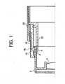
- a lens barrel according to the present invention comprises a moving frame 2 to hold a lens 8, a direct-advance ring 4 disposed on an outer periphery of the moving frame 2 and movable relative to the moving frame in an optical direction, and a resilient member 6 disposed between the moving frame 2 and the direct-advance ring 4.
- the resilient member 6 comprises, preferably a spring or rubber.
- the resilient member 6 comprises an O-ring attached to the moving frame 2.
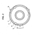
- Figs. 2 and 3 show the moving frame 2 and the direct-advance ring 4 as viewed from the opposite side to a subject.
- the moving frame 2 is provided with one or more control parts 10 to control the movement of the direct-advance ring 4 in the optical direction.
- the direct-advance ring 4 is provided with one or more cutout portions, in which the control part 10 can be inserted. In a position shown in Fig. 2 , the control part 10 is inserted into the cutout portion 4a and the direct-advance ring 4 is rotated relative to the moving frame 2 in arrow direction (see Fig. 2 ) to set the direct-advance ring 4 on the moving frame 2.
- control members 12 for example, pins as rotational control means are provided on the direct-advance ring 4 in order to control movement of the direct-advance ring in a rotational direction (see Fig. 3 ).
- the control member 12 is fixed in the direct-advance ring 4 by press-fitting, adhesion or the like.
- the moving frame 2 is provided with a slit 14 in which the control member 12 is fitted, thereby the direct-advance ring 4 is movable relative to the moving frame 2 by an amount only in the optical direction.
- the resilient member 6 deforms to lessen a distance between the moving frame 2 and the direct-advance ring 4.
- the moving frame 2 and the direct-advance ring 4 can be returned in an original position by means of a biasing force of the resilient member 6.
- the direct-advance ring 4 is provided with one or more tapered pins 4b to engage with a cam frame 16, for example (see Fig. 1 ).
- the cam frame 16 is rotated through a gear driving mechanism (not shown).
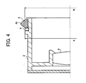
- Fig. 4 shows a size relationship between the direct-advance ring 4 and the moving frame 2.
- a size B of an outer diameter of the direct-advance ring 4 slides with an inner diameter of the cam frame 16, accuracy of the outer size is required.
- setting a size of an outer diameter A of the moving frame 2 to the same manner as the size B is expensive or requires a long time for keeping the accuracy. Therefore, a simple lens barrel can be performed by securing the accuracy about only the size B of the direct-advance ring 4 to the cam frame 16 and lessening the size A of the direct advance ring 4 than the size B.
- Figs. 5 to 7 illustrate a second embodiment of the present invention.
- a lens barrel in the second embodiment comprises a moving frame 2 to hold a lens 8, a direct-advance ring 4 disposed on an outer periphery of the moving frame 2 and movable relative to the moving frame in an optical direction, and a resilient member 6 disposed between the moving frame 2 and the direct-advance ring 4, similarly as the first embodiment.
- the resilient member 6, also, comprises, preferably a spring or rubber.
- the resilient member 6, also, comprises an O-ring attached to the moving frame 2.
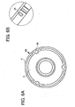
- Figs. 6 and 7 show the moving frame 2 and the direct-advance ring 4 as viewed from the opposite side to the subject.
- a direct-advance guiding member 22 which moves with, for example, the cam frame 16 in the optical direction and is regulated by a fixing frame 20 to perform only direct movement.
- the moving frame 2 is controlled by means of the direct-advance guiding member 22 to be movable only direct advance.
- the moving frame 2 is provided with a rotational control part 30 to control the movement of the direct-advance ring 4 in a rotational direction
- a pin 32 is provided as a control part to regulate an amount of movement of the direct-advance ring 4 in the optical direction at a constant position of the moving frame 2 and the direct-advance ring 4.
- the pin 32 is fixed to the direct-advance ring 4 by press-fitting or adhesion, a leading end of the pin 32 is inserted into, for example, a hole 34, of the moving frame (see Fig. 6 ) to regulate the moved amount of the direct-advance ring 4 in the optical direction. Consequently, when an impact is imparted from a direction of the subject to the moving frame 2 in the state shown in Fig. 5 , because the pin 32 of the direct-advance ring 4 is engaged with the cam frame 16, the resilient member 6 provided between the moving frame 2 and the direct-advance ring 4 deforms to allow the impact to absorb.
- control part to control the movement of the direct-advance ring 4 in the optical direction may be a plate-shaped member 10A attached to a back end surface of the moving frame 2, by, for example, a screw 25.
- Fig. 11 to 13 illustrates a third embodiment of the present invention.
- a lens barrel in the embodiment comprises a moving frame 2 to hold a lens 8, a direct-advance ring 4 disposed on an outer periphery of the moving frame 2 and movable relative to the moving frame in an optical direction, and a resilient member 6 disposed between the moving frame 2 and the direct-advance ring 4, similarly as the above-mentioned embodiments.
- the resilient member 6, also, comprises, preferably a spring or rubber.
- the resilient member 6, also, comprises an O-ring attached to the moving frame 2.
- Figs. 12 and 13 show the moving frame 2 and the direct-advance ring 4 as viewed from the opposite side to the subject.
- a plurality of shafts 40 which are engaged with the cam frame 16 and so on, and control the movements of the direct-advance ring 4 in the rotational and optical directions relative to the moving frame 2.
- the plurality of shafts 40 is fixed to the direct-advance ring 4 by press-fitting or adhesion.
- the moving frame 2 is provided with elongate holes 46 (see Fig. 12 ), for example, in which the plurality of shafts 40 are fitted so as to form engaging parts for controlling the movements of the direct-advance ring 4 in the rotational and optical directions. Consequently, when an impact is added from the direction of the subject to the moving frame 2, in the state shown in Fig. 11 , because the plurality of shafts 40 provided on the direct-advance ring 4 are engaged with the cam frame 16, the resilient member 6 deforms to allow the impact to absorb.
- Fig. 14 illustrates a fourth embodiment of the present invention.
- the moving frame 2 is provided with elongate concave portions 41, for example, to control the movements of the direct-advance ring 4 in the rotational and optical directions.
- Leading ends of the plurality of shafts 40 are inserted into the elongate concave portions 41.
- the plurality of shafts 40 are engaged with the cam frame 16 and fixed to the direct-advance ring 4 by press-fitting or adhesion, as described above. It is possible to accomplish the lens barrel of the prescribed objects by setting the resilient member 6 within a space of the subject side of each shaft 40 in the optical direction in each concave portion 41.
- cam frame 16 in the above-mentioned embodiments has a taper formed to enlarge inwardly of the cam frame and the shaft has a taper to engage with the taper of the cam frame
- a taper enlarging from an inner diameter to an outer diameter may be formed in the cam frame 16 and a straight shaft may be fitted in the taper of the cam frame.
- a lens barrel 51 shown in the embodiment holds one or more lenses and is installed in various optical devices such as a silver film camera, digital camera of electronic camera, video camera or the like.
- the lens barrel 51 includes a cylindrical fixing frame 52 to support a lens (not shown) and one or more mounting members 53 which are provided to project on an outer peripheral surface of the fixing frame 52 and spaced from each other with a predetermined pitch, as an example, 120 degrees, as a means for fixing the fixing frame 52 on a mounted part 61 of a body 60 of an optical device.
- the mounting member 53 is formed from a hog-backed thin plate.
- the mounting member may be formed integrally with the fixing frame 52 at the outer peripheral surface thereof, or a previously formed mounting member may be attached to the fixing frame, later.
- the mounting member 53 in the embodiment is fixed to the mounted part 61 of the body of the device through a fastening member 54 such as a screw.
- a resilient member 55 is disposed in a clearance between the mounted part 61 and the mounting member 53 in a compressed state, to be variable resiliently a space between the mounted part 61 and the mounting member 53 in an optical direction.
- the resilient member 55 comprises an annular rubber, spring washer, spring or the like.
- the mounted part 61 and the mounting member 53 are configured not to contact directly in at least optical direction and to be variable a space of the aforementioned clearance through the resilient member 55.
- the mounting member 53, mounted part 61, fastening member 54 and resilient member 55 constitute a mounting mechanism of the lens barrel.
- Each mounting member 53 is provided with previously formed one or more holes for inserting a screw or the like, and a small sleeve engaging with an inner periphery of the resilient member is provided at a peripheral edge portion of the hole.
- a clearance jig 56 is previously inserted into a space of an outer diameter side of the resilient member 55 in order to assemble accurately a positional relationship of the mounted part 61 and the mounting member 53 in the optical direction, and the mounting member 53 or the fixing frame 52 is fixed to the mounted part 61 through a fastening member or screw or the like. Thereafter, if the clearance jig 56 is removed out in a direction shown by arrow in Fig. 15A , for example, the assembly is completed.
- the clearance jig 56 is formed, for example, by a plate material, which has at a leading end thereof a hog-backed concave cutout, for example.
- the resilient member 55 is compressed by a predetermined amount between the mounting member 53 and the mounted part 61, and is structured to urge always the fixing frame toward the subject with a pressure.
- the impact strength when impact strength is added to, for example, a direct-advance cylinder, which is supported movably by the fixing frame 52 in the optical direction, the impact strength can be absorbed by reduction of a size of the resilient member 55 disposed between the fixing frame 52 and the body 60. If the impact strength is removed, the fixing frame 52 can be returned to an original position by a basing force of the resilient member 55 to an original position.
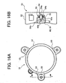
- FIGs. 16A and 16B illustrate a structure of a mounting mechanism in a lens barrel in an example not forming part of the present invention.
- the mounting mechanism in the example has features that the fastening member 54 comprises a stepped screw and the mounted part 61 is adapted to receive the stepped screw.
- the fastening member or stepped screw 54 is composed of a head portion 54a, a large diametric cylindrical non-threaded portion 54b extending from the head portion 54a and a small diametric threaded portion 54c, which are integrally formed.
- the mounted part 61 is provided with a stepped hole 62 inserting the stepped screw 54.
- the stepped hole 62 includes a large diametric portion 62a having an inner diameter engaging with the non-threaded portion 54b and a threaded hole portion 62b into which the threaded portion 54c is engaged.
- the resilient member 55 such as rubber or spring or the like is provided between the mounting member 53 formed in the fixing frame 52 and the mounted part 61 of the body 60.
- the resilient member is fixed by means of the fastening member 4 such as a stepped screw or the like in order to secure a position of the fixing frame and the body 60 in the optical direction.
- the resilient member 55 is compressed by a constant amount between the mounted part 61 and the mounting member 54 to bias constantly the fixing frame 2 in the direction of the subject under a pressure. Accordingly, if an impact strength is applied to the direct-advance cylinder (not shown) run out from the fixing frame, for example, the impact strength can be absorbed by contraction of the size of the resilient member 55 disposed between the fixing frame and the body of the device. Meanwhile, if the impact strength is removed, the fixing frame is returned to the original position by the biasing force of the resilient member.
- Figs. 17 , 18 and 19 illustrate a structure of a lens barrel in a an example not forming part of the present invention.
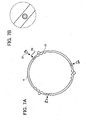
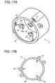
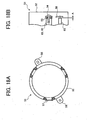
- the lens barrel 51 in the example includes one or more engaging holes 57 which are disposed with a predetermined space on a periphery of the fixing frame 52 to attach a separate mounting member 53 therein.
- the engaging hole has a rectangular shape (see Fig. 17A ).
- the mounting member 53 has a body, which can be fitted in the engaging hole 57 from an inner side of the fixing frame (see Figs. 17A, 17B and 19 ).
- the mounting member 53 is made of a resilient thermoplastic resin, for example, a resilient resin such as rubber or elastomer resin.
- the mounting member 53 includes an engaging portion 53a provided on a basic end thereof and having a shape larger than the engaging hole 57 of the fixing frame 52, and engaging protrusions 53b provided adjacent to the engaging portion 53a.
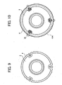
- an engaging projection 57a is provided in the engaging hole 57 (see Fig. 9 ).
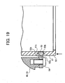
- the mounting member 53 is inserted in the engaging hole 57 from the inner side of the fixing frame 52 until the engaging portion 53a is contacted with an inner surface of the fixing frame 52. At the time of this insertion, as shown in Fig. 19 , the engaging projection 57a of the engaging hole 57 is inserted non-detachably between the engaging portion 53a and the engaging protrusions 53b in the mounting member 53 to lock the mounting member 53 to the fixing frame 52.
- Fig. 17B illustrates a state after the mounting member is secured to the fixing frame.
- the engaging protrusions 53b are deformed because the mounting member 53 is made of the resilient resin when the engaging projection 57a is inserted between the engaging portion 53a and the engaging protrusions 53b.
- the mounted part 61 of the body 60 of the device and the mounting member 53 are fixed by fastening members, for example, screws 54 (see Fig. 19 ).
- the screws may be any configuration, for example, stepped screws.
- positional members 58 are provided to project from an outer periphery of the fixing frame 52 for securing the positional accuracy relative to the body 60 of the device.
- the positional member 58 is disposed to set a space A between the positional member 58 and a positional boss portion 65 fixed on the body 60, as shown in Fig. 18B .
- the positional member 58 deforms to absorb the impact strength. If the impact strength is removed, the fixing frame is returned to the original position by a reactive force of the mounting member.
- Fig. 20 illustrates a lens barrel not part of the present invention.
- the lens barrel includes one or more latching projections 59 provided at a mounting position of the mounting member on the outer periphery of the fixing frame 52 made of the thermoplastic resin.
- the latching projection is made of the same material as the fixing frame 52.
- the mounting member 53 made of the resilient thermoplastic resin of the resilient resin such as rubber or elastomer resin is integrated with the latching projection 59.
- FIGs. 21A and 21B illustrate schematically a structure of a die for forming the fixing frame. Meanwhile, a structural example for forming a site of the fixing frame for mounting the mounting member is shown in Figs. 21A and B .
- Fig. 21A illustrates a structural example of the die to form the fixing frame 52 made of the thermoplastic resin.
- the die includes a first fixed mold 70, and first and second movable molds 71, 72 to form cavities 73 or portions for filling a thermoplastic resin, among the first fixed mold 70 and the first and second movable molds 71,72.
- a melted thermoplastic resin is poured from a resin passage (not shown) provided in the first fixed mold 70 into the cavities 73 so that the forming is performed.
- the first fixed mold 70 is retracted, while, at this time, molded goods of the thermoplastic resin continue to be held by a forming surface of the movable mold 71 or 72.
- a second fixed mold 74 is moved at the same position as the operational position of the first fixed mold to define cavities 75 among the second fixed mold 74 and the forming surfaces of the first and second movable molds 71 and 72.
- the fluid thermoplastic resin is injected from a resin passage (not shown) into the cavities 75 so that the mounting member 53 of the thermoplastic resin is integrally formed.
- the impact strength is applied to the direct-advance cylinder which is not shown, run out from the fixing frame 52, for example, the mounting member 53 resiliently deforms so that the impact strength can be absorbed. If the impact strength is removed, the fixing frame is returned to the original position by the reactive force of the mounting member.
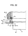
- Fig. 22 illustrates a structure of a substantial portion of a lens barrel not part of the present invention.
- a belt-shaped projection 100 is provided to extend throughout the entire periphery of a forward side of the fixing frame 52, an exterior member 80 is assembled to cover the outer surface of the fixing frame 52 and a resilient member 81 is formed from an annular O-ring made of a resilient material such as rubber or elastomer resin or the like and is disposed between the belt-shaped projection 100 and the exterior member 80.
- a protrusion 80a is provided on an inner surface of the exterior member 80 to define a space for housing the resilient member 81 between the projection 100 and the protrusion 80a.
- the resilient member 81 is disposed between the protrusion 80a provided inside the exterior member 80 disposed in a front of the optical device such as a camera and the projection 100 of the fixing frame, equalization of an entire peripheral clearance B can be achieved and exterior performance of the lens barrel can be enhanced. If an impact strength is added laterally of a rotational cylinder 90, the fixing member 52 is difficult to deform because it is biased always toward the peripheral direction thereof by the resilient member 81, and because concentricity of the exterior member 80 and the fixing member 52 can be secured, the rotational cylinder or direct-advance cylinder 90 and the exterior member are not contacted, and therefore generation of outer scratch of the exterior member and so on can be prevented.
- the lens barrel of the present invention can be applied to a photographing optical apparatus such as a camera having a structure for supporting a fixed lens, video camera or the like, or an image inputting apparatus including an optical element.
- a photographing optical apparatus such as a camera having a structure for supporting a fixed lens, video camera or the like, or an image inputting apparatus including an optical element.
- the optical apparatus using the lens barrel is strong against an impact from exterior of the lens barrel, the fixing frame and the lens can be prevented from breakage.
- the resilient member is disposed between the moving frame and the direct-advance ring, when the an impact strength is added to the moving frame, the resilient member deforms to absorb the impact strength, and therefore it is possible to provide a lens barrel in which anti-impact is high and breakage and so on can be prevented.
- an example adopts a structure in which when the mounting member projected from the outer peripheral surface of the fixing frame is mounted on the mounted part of the body of the device by the fastening member, the resilient member is disposed between the mounting member and the mounted part, it is possible to provide a lens barrel, camera or photographing optical apparatus in which the structure is simplified while its anti-impact is enhanced, and therefore the breakage of the parts and so on of the lens barrel can be prevented.
Landscapes
- Physics & Mathematics (AREA)
- General Physics & Mathematics (AREA)
- Optics & Photonics (AREA)
- Lens Barrels (AREA)
Claims (6)
- Corps d'objectif, comportant,
un support mobile (2) destiné à supporter un objectif (8) ; et
une bague d'avance directe (4), qui est prévue sur une périphérie extérieure du support mobile (2) et est mobile par rapport au support mobile (2) dans une direction d'axe optique de l'objectif (8),
caractérisé en ce qu'il comporte :un support de came (16), qui est disposé sur une périphérie extérieure de la bague d'avance directe (4) et peut tourner autour de l'axe optique ;un axe (4b), qui dépasse vers le support de came (16) depuis une face périphérique extérieure de la bague d'avance directe (4) afin d'engager le support de came (16), et fixe la bague d'avance directe (4) sur le support de came (16) dans un état tel qu'un mouvement le long de la direction d'axe optique est commandé par engagement avec le support de came (16) ;un élément élastique (6), qui est fixé sur le support mobile (2) entre le support mobile et la bague d'avance directe (4), et est comprimé entre la bague d'avance directe (4) et le support mobile (2) par un mouvement de la bague d'avance directe (4) dans une direction le long de la direction d'axe optique ; etune partie de commande (10) prévue sur le support mobile (2) afin de commander la valeur de déplacement de la bague d'avance directe (4) dans la direction d'axe optique,l'axe (4b) étant guidé dans la direction d'axe optique par la rotation du support de came (16), de façon à déplacer le support mobile (2) le long de la direction d'axe optique, etla bague d'avance directe (4) se déplaçant de manière relative avec le mouvement du support mobile (2) le long de la direction d'axe optique, quand des forces d'impact agissent sur le support mobile (2) le long de la direction d'axe optique, de sorte que l'élément élastique (6) est comprimé de façon à absorber les forces d'impact agissant sur le support mobile (2). - Corps d'objectif selon la revendication 1, dans lequel l'élément élastique (6) comporte un élément torique fixé sur la périphérie extérieure du support mobile (2).
- Corps d'objectif selon la revendication 1 ou 2, dans lequel la bague d'avance directe (4) est pourvue d'une partie de découpe (4a) sur laquelle est montée la partie de commande (10).
- Corps d'objectif selon la revendication 3, dans lequel, lors de l'assemblage de la bague d'avance directe (4) sur le support mobile (2), la partie de commande (10) est assemblée dans une position de la partie de découpe (4a) et la bague d'avance directe (4) est tournée dans une direction prédéterminée de façon à assembler la bague d'avance directe (4) sur le support mobile (2).
- Corps d'objectif selon la revendication 1, dans lequel un élément de commande de rotation (12), qui commande le mouvement de la bague d'avance directe (4) dans la direction de rotation, est fixé sur la bague d'avance directe (4), et est monté sur le support mobile (2).
- Appareil optique comportant un corps d'objectif selon l'une quelconque des revendications précédentes.
Priority Applications (1)
| Application Number | Priority Date | Filing Date | Title |
|---|---|---|---|
| EP06009341.6A EP1701191B1 (fr) | 2003-08-12 | 2004-08-09 | Fixation pour barillet d'objectif |
Applications Claiming Priority (4)
| Application Number | Priority Date | Filing Date | Title |
|---|---|---|---|
| JP2003292055A JP2005062445A (ja) | 2003-08-12 | 2003-08-12 | レンズ鏡筒 |
| JP2003292055 | 2003-08-12 | ||
| JP2003399418A JP4402942B2 (ja) | 2003-11-28 | 2003-11-28 | レンズ鏡筒、カメラ及び光学機器 |
| JP2003399418 | 2003-11-28 |
Related Child Applications (1)
| Application Number | Title | Priority Date | Filing Date |
|---|---|---|---|
| EP06009341.6A Division EP1701191B1 (fr) | 2003-08-12 | 2004-08-09 | Fixation pour barillet d'objectif |
Publications (3)
| Publication Number | Publication Date |
|---|---|
| EP1512997A2 EP1512997A2 (fr) | 2005-03-09 |
| EP1512997A3 EP1512997A3 (fr) | 2005-07-27 |
| EP1512997B1 true EP1512997B1 (fr) | 2009-03-18 |
Family
ID=34137958
Family Applications (2)
| Application Number | Title | Priority Date | Filing Date |
|---|---|---|---|
| EP04254793A Expired - Lifetime EP1512997B1 (fr) | 2003-08-12 | 2004-08-09 | Tube de lentille |
| EP06009341.6A Expired - Lifetime EP1701191B1 (fr) | 2003-08-12 | 2004-08-09 | Fixation pour barillet d'objectif |
Family Applications After (1)
| Application Number | Title | Priority Date | Filing Date |
|---|---|---|---|
| EP06009341.6A Expired - Lifetime EP1701191B1 (fr) | 2003-08-12 | 2004-08-09 | Fixation pour barillet d'objectif |
Country Status (3)
| Country | Link |
|---|---|
| US (2) | US7259923B2 (fr) |
| EP (2) | EP1512997B1 (fr) |
| DE (1) | DE602004020034D1 (fr) |
Families Citing this family (26)
| Publication number | Priority date | Publication date | Assignee | Title |
|---|---|---|---|---|
| DE602004020034D1 (de) | 2003-08-12 | 2009-04-30 | Ricoh Kk | Linsenfassung |
| JP4541054B2 (ja) * | 2004-07-09 | 2010-09-08 | 株式会社リコー | レンズ鏡胴及び撮影装置 |
| JP4390199B2 (ja) * | 2004-07-26 | 2009-12-24 | 株式会社リコー | レンズ鏡胴、カメラおよび携帯型情報端末装置 |
| JP4463034B2 (ja) * | 2004-07-26 | 2010-05-12 | 株式会社リコー | レンズ鏡胴、カメラおよび携帯型情報端末装置 |
| TWI288258B (en) * | 2005-05-27 | 2007-10-11 | Powergate Optical Inc | Auto-focusing device for lens |
| JP4645328B2 (ja) * | 2005-07-04 | 2011-03-09 | コニカミノルタオプト株式会社 | レンズ鏡胴及びカメラ |
| TWI283792B (en) * | 2005-10-06 | 2007-07-11 | Benq Corp | Projector with a lens capable of shifting in two dimensions |
| JP2007114283A (ja) * | 2005-10-18 | 2007-05-10 | Ricoh Co Ltd | 画像入力装置 |
| JP4719595B2 (ja) * | 2006-03-09 | 2011-07-06 | 株式会社タムロン | レンズ鏡筒及び光学装置 |
| JP2008028963A (ja) * | 2006-07-25 | 2008-02-07 | Ricoh Co Ltd | 画像入力装置 |
| JP4726754B2 (ja) * | 2006-09-19 | 2011-07-20 | 株式会社リコー | レンズ鏡胴、及び撮像装置 |
| JP2008224795A (ja) | 2007-03-09 | 2008-09-25 | Ricoh Co Ltd | レンズ鏡胴および携帯型情報端末装置 |
| US7907836B2 (en) | 2007-09-12 | 2011-03-15 | Ricoh Company, Ltd. | Imaging apparatus |
| JP2009237530A (ja) * | 2007-11-14 | 2009-10-15 | Ricoh Co Ltd | レンズ駆動装置、撮像装置およびレンズ駆動方法 |
| JP5365470B2 (ja) * | 2008-11-26 | 2013-12-11 | 株式会社リコー | カメラボディ、撮像ユニット、撮像システム、その撮像ユニットのカメラボディに対する着脱方法、その撮像ユニットのカメラボディに対する装着方法、その撮像ユニットのカメラボディに対する抜き取り方法 |
| EP2399164B1 (fr) | 2009-02-19 | 2018-06-27 | Ricoh Company, Ltd. | Boîtier d'appareil photo, unité d'imagerie montée / démontée sur / du boîtier d'appareil photo et appareil d'imagerie |
| JP5445038B2 (ja) | 2009-09-14 | 2014-03-19 | 株式会社リコー | カメラボディ及びこのカメラボディに着脱される撮像ユニット及び撮像装置 |
| JP5413133B2 (ja) * | 2009-11-05 | 2014-02-12 | 株式会社リコー | カメラボディ及びこのカメラボディに着脱される撮像ユニット及び撮像装置 |
| JP5454089B2 (ja) * | 2009-11-09 | 2014-03-26 | 株式会社リコー | カメラボディおよび撮像装置 |
| JP5574157B2 (ja) * | 2010-03-16 | 2014-08-20 | 株式会社リコー | 撮像装置の組み立て方法および撮像装置 |
| JP5887544B2 (ja) | 2010-07-16 | 2016-03-16 | パナソニックIpマネジメント株式会社 | レンズ鏡筒の支持構造、および光学機器 |
| CN102375308A (zh) * | 2010-08-13 | 2012-03-14 | 中强光电股份有限公司 | 投影机 |
| JP5853175B2 (ja) | 2011-03-28 | 2016-02-09 | パナソニックIpマネジメント株式会社 | 撮像装置 |
| US8830607B2 (en) * | 2012-04-10 | 2014-09-09 | Canon Kabushiki Kaisha | Image pickup apparatus capable of interchanging lenses and lens mount therefor |
| KR102279920B1 (ko) * | 2020-02-10 | 2021-07-22 | 삼성전기주식회사 | 카메라 모듈 |
| CN116339043A (zh) | 2021-12-22 | 2023-06-27 | 中强光电股份有限公司 | 投影机 |
Family Cites Families (67)
| Publication number | Priority date | Publication date | Assignee | Title |
|---|---|---|---|---|
| US3561432A (en) * | 1967-07-29 | 1971-02-09 | Olympus Optical Co | Endoscope |
| US3663093A (en) * | 1969-08-08 | 1972-05-16 | Nippon Kogaku Kk | Varifocal lens mount with deformable anti-friction coatings |
| JPS548097B1 (fr) * | 1971-04-16 | 1979-04-12 | ||
| JPS5929842B2 (ja) | 1977-04-08 | 1984-07-24 | ミノルタ株式会社 | 移動装置 |
| JPS612984Y2 (fr) | 1977-10-24 | 1986-01-30 | ||
| JPS5559410A (en) * | 1978-10-27 | 1980-05-02 | Minolta Camera Co Ltd | Zoom lens barrel which permits operation in two kinds of directions |
| JPS55166610A (en) * | 1979-06-13 | 1980-12-25 | Canon Inc | Cam mechanism of zoom lens |
| US4303324A (en) * | 1980-10-06 | 1981-12-01 | Eastman Kodak Company | Annular piezoelectric plastic bender lens motor |
| JPS619370Y2 (fr) * | 1980-11-28 | 1986-03-25 | ||
| US4498754A (en) | 1982-01-25 | 1985-02-12 | Ricoh Company, Ltd. | Single lens reflex camera |
| JPH0672973B2 (ja) | 1983-06-30 | 1994-09-14 | 株式会社リコー | オ−トフオ−カス方法 |
| JPS60237414A (ja) * | 1984-05-11 | 1985-11-26 | Hitachi Ltd | ズ−ムレンズ鏡胴マウント機構 |
| US4707083A (en) | 1984-09-29 | 1987-11-17 | Canon Kabushiki Kaisha | Lens moving device |
| JPH052911Y2 (fr) | 1986-10-28 | 1993-01-25 | ||
| JPS63101927U (fr) | 1986-12-23 | 1988-07-02 | ||
| JPS63199332A (ja) | 1987-02-14 | 1988-08-17 | Ricoh Co Ltd | 可変焦点カメラにおけるバリア駆動装置 |
| US5037195A (en) | 1987-12-21 | 1991-08-06 | Clairmont Camera, Inc. | Sound-damping lens adapter for a motion-picture camera |
| US4950061A (en) | 1987-12-23 | 1990-08-21 | Ricoh Company, Ltd. | Drive device for a varifocal lens system |
| US5335115A (en) * | 1989-02-23 | 1994-08-02 | Canon Kabushiki Kaisha | Lens barrel |
| US5146254A (en) | 1989-04-19 | 1992-09-08 | Ricoh Company, Ltd. | Apparatus for driving varifocal lens |
| JP2532709Y2 (ja) | 1989-04-20 | 1997-04-16 | 株式会社リコー | プラスチックレンズの静電防止装置 |
| JPH0740986Y2 (ja) * | 1989-05-24 | 1995-09-20 | 旭光学工業株式会社 | 遮光構造 |
| JPH0344182A (ja) | 1989-07-11 | 1991-02-26 | Ricoh Co Ltd | 静止画記録装置 |
| JP2512080Y2 (ja) | 1989-10-09 | 1996-09-25 | 株式会社リコー | テレビモ―ドを持つカメラ |
| US5216314A (en) * | 1989-11-16 | 1993-06-01 | Canon Kabushiki Kaisha | Pressure force adjusting mechanism for a vibration wave driven motor |
| US5274413A (en) * | 1990-02-14 | 1993-12-28 | Asahi Kogaku Kogyo Kabushiki Kaisha | Mount assembly of optical devices |
| US5270755A (en) | 1990-05-01 | 1993-12-14 | Ricoh Company, Ltd. | Trimming information recordable camera |
| JPH07175119A (ja) | 1990-05-01 | 1995-07-14 | Ricoh Co Ltd | トリミング撮影可能なカメラ |
| JPH04226409A (ja) | 1990-06-05 | 1992-08-17 | Ricoh Co Ltd | 焦点状態検出装置 |
| JP3118610B2 (ja) | 1990-09-18 | 2000-12-18 | 株式会社リコー | 焦点状態検出装置 |
| JP3066541B2 (ja) | 1991-01-18 | 2000-07-17 | 株式会社リコー | 2群構造のズームレンズ装置 |
| US5392159A (en) | 1991-01-18 | 1995-02-21 | Ricoh Company, Ltd. | Zoom lens device of two-lens group structure and driving device of varifocal lens of two-lens group structure |
| US5192964A (en) | 1991-03-04 | 1993-03-09 | Ricoh Company, Ltd. | Camera having blurring movement correction mechanism |
| JPH04355436A (ja) | 1991-05-31 | 1992-12-09 | Ricoh Co Ltd | 手ぶれ補正機能付きカメラ |
| JPH0627520A (ja) | 1992-07-06 | 1994-02-04 | Canon Inc | 光学機器 |
| US6002886A (en) * | 1992-10-01 | 1999-12-14 | Canon Kabushiki Kaisha | Lens barrel |
| JP3435206B2 (ja) * | 1994-03-29 | 2003-08-11 | ペンタックス株式会社 | 部材の結合構造 |
| DE4411516B4 (de) | 1994-04-02 | 2005-12-22 | Carl Zeiss Ag | Spielfreies Kurvengetriebe |
| JPH08227097A (ja) | 1995-02-21 | 1996-09-03 | Ricoh Co Ltd | カメラ装置 |
| JPH08334669A (ja) * | 1995-06-07 | 1996-12-17 | Nikon Corp | レンズ鏡筒 |
| JP2864363B2 (ja) | 1995-09-27 | 1999-03-03 | 株式会社リコー | レンズ鏡胴 |
| GB2318191B (en) * | 1996-10-14 | 2001-10-03 | Asahi Seimitsu Kk | Mount shift apparatus of lens for cctv camera |
| JPH11119082A (ja) * | 1997-10-17 | 1999-04-30 | Canon Inc | 光学鏡筒及び該鏡筒を用いた光学装置 |
| US5926322A (en) * | 1997-08-04 | 1999-07-20 | Fuji Photo Film Co., Ltd. | Zoom lens device with zooming position detector |
| JP3878336B2 (ja) | 1998-07-10 | 2007-02-07 | 株式会社シグマ | レンズマウント |
| US6204979B1 (en) * | 1998-08-21 | 2001-03-20 | Fuji Photo Optical Co., Ltd. | Lens assembly and eccentricity adjustment apparatus thereof |
| US6409658B1 (en) * | 1998-12-14 | 2002-06-25 | Fuji Photo Optical Co., Ltd. | Endoscope with objective lens drive mechanism |
| JP2000193873A (ja) | 1998-12-25 | 2000-07-14 | Canon Inc | レンズ鏡筒 |
| JP2001116974A (ja) | 1999-10-21 | 2001-04-27 | Olympus Optical Co Ltd | レンズ鏡筒及びカメラ |
| US20020163259A1 (en) | 1999-12-17 | 2002-11-07 | Ricoh Company, Ltd. | DC motor |
| CN1222103C (zh) | 1999-12-27 | 2005-10-05 | 株式会社理光 | 直流马达的回转控制装置 |
| US6628893B2 (en) | 2000-01-06 | 2003-09-30 | Ricoh Company, Ltd. | DC motor rotation control apparatus |
| CN1152463C (zh) | 2000-06-09 | 2004-06-02 | 株式会社理光 | 直流马达 |
| US6570350B2 (en) | 2000-06-20 | 2003-05-27 | Ricoh Company, Ltd. | DC motor rotation detecting apparatus and DC motor rotation control apparatus |
| JP4511766B2 (ja) | 2000-07-10 | 2010-07-28 | 株式会社リコー | 撮影装置および撮影装置における振れ補正方法 |
| JP2002218328A (ja) | 2001-01-19 | 2002-08-02 | Ricoh Co Ltd | 画像入力装置、画像入力方法、およびその方法を実行するためのプログラムを格納したことを特徴とするコンピュータが読み取り可能な記録媒体 |
| JP3529369B2 (ja) * | 2001-04-06 | 2004-05-24 | Necビューテクノロジー株式会社 | 投写レンズシフト機構 |
| JP4761099B2 (ja) * | 2001-07-16 | 2011-08-31 | ソニー株式会社 | 光学装置 |
| JP3961797B2 (ja) * | 2001-08-28 | 2007-08-22 | ペンタックス株式会社 | レンズ光軸調整装置 |
| JP3921069B2 (ja) | 2001-10-15 | 2007-05-30 | 株式会社リコー | 撮像装置 |
| JP3990904B2 (ja) * | 2001-12-03 | 2007-10-17 | キヤノン株式会社 | カメラ |
| JP3992992B2 (ja) | 2002-02-19 | 2007-10-17 | 株式会社リコー | 被写体像取得装置 |
| JP3767745B2 (ja) | 2002-06-17 | 2006-04-19 | 株式会社リコー | オートフォーカス装置および電子カメラ |
| JP3926707B2 (ja) | 2002-08-20 | 2007-06-06 | 株式会社リコー | 画像入力装置 |
| US6978088B2 (en) * | 2002-08-27 | 2005-12-20 | Pentax Corporation | Optical element retracting mechanism for a retractable lens |
| US6959148B2 (en) * | 2002-08-27 | 2005-10-25 | Pentax Corporation | Retractable photographing lens |
| DE602004020034D1 (de) | 2003-08-12 | 2009-04-30 | Ricoh Kk | Linsenfassung |
-
2004
- 2004-08-09 DE DE602004020034T patent/DE602004020034D1/de not_active Expired - Lifetime
- 2004-08-09 EP EP04254793A patent/EP1512997B1/fr not_active Expired - Lifetime
- 2004-08-09 EP EP06009341.6A patent/EP1701191B1/fr not_active Expired - Lifetime
- 2004-08-09 US US10/913,549 patent/US7259923B2/en not_active Expired - Fee Related
-
2007
- 2007-06-14 US US11/763,169 patent/US7505216B2/en not_active Expired - Fee Related
Also Published As
| Publication number | Publication date |
|---|---|
| US20080252999A1 (en) | 2008-10-16 |
| EP1512997A3 (fr) | 2005-07-27 |
| US7259923B2 (en) | 2007-08-21 |
| EP1701191A3 (fr) | 2006-09-20 |
| EP1701191B1 (fr) | 2014-07-23 |
| EP1701191A2 (fr) | 2006-09-13 |
| DE602004020034D1 (de) | 2009-04-30 |
| EP1512997A2 (fr) | 2005-03-09 |
| US20050068638A1 (en) | 2005-03-31 |
| US7505216B2 (en) | 2009-03-17 |
Similar Documents
| Publication | Publication Date | Title |
|---|---|---|
| EP1512997B1 (fr) | Tube de lentille | |
| US4707083A (en) | Lens moving device | |
| US20200200240A1 (en) | Lens barrel and cam follower | |
| JPH02220014A (ja) | ズームレンズ鏡筒 | |
| US10739553B2 (en) | Lens barrel and optical apparatus | |
| US10120161B2 (en) | Lens barrel and optical apparatus having the same | |
| US11906880B2 (en) | Cam follower and lens barrel | |
| US4514039A (en) | Lens mounting | |
| US5886832A (en) | Lens barrel and CAM mechanism therefor | |
| US20160077304A1 (en) | Lens barrel and optical apparatus | |
| US5216549A (en) | Lens barrel | |
| JP4443381B2 (ja) | レンズ鏡筒 | |
| JP4343569B2 (ja) | レンズ鏡筒 | |
| JP2001042189A (ja) | レンズ移動装置 | |
| JP2003295032A (ja) | レンズ駆動装置 | |
| JP5388624B2 (ja) | レンズ鏡筒及びそれを有する光学機器 | |
| JP4402942B2 (ja) | レンズ鏡筒、カメラ及び光学機器 | |
| JP2992094B2 (ja) | レンズ保持部材 | |
| JP4623997B2 (ja) | 鏡筒装置 | |
| JP4708841B2 (ja) | レンズ鏡筒及び該レンズ鏡筒を備える撮像装置 | |
| US7623302B2 (en) | Cam drive mechanism, lens barrel and camera | |
| JP2005224056A (ja) | モータの制振取付構造 | |
| JP4762751B2 (ja) | 芯調整装置 | |
| KR20170130836A (ko) | 카메라 모듈 | |
| JPS6211815A (ja) | レンズ保持装置 |
Legal Events
| Date | Code | Title | Description |
|---|---|---|---|
| PUAI | Public reference made under article 153(3) epc to a published international application that has entered the european phase |
Free format text: ORIGINAL CODE: 0009012 |
|
| 17P | Request for examination filed |
Effective date: 20040814 |
|
| AK | Designated contracting states |
Kind code of ref document: A2 Designated state(s): AT BE BG CH CY CZ DE DK EE ES FI FR GB GR HU IE IT LI LU MC NL PL PT RO SE SI SK TR |
|
| AX | Request for extension of the european patent |
Extension state: AL HR LT LV MK |
|
| PUAL | Search report despatched |
Free format text: ORIGINAL CODE: 0009013 |
|
| RIC1 | Information provided on ipc code assigned before grant |
Ipc: 7G 02B 7/02 A Ipc: 7G 03B 17/02 B |
|
| RIN1 | Information on inventor provided before grant (corrected) |
Inventor name: SHINOHARA, JUNICHI Inventor name: NUNO, KATSUHIKO Inventor name: ETOH, AKIHIRO Inventor name: TSURUKAWA, IKUYA Inventor name: ITOH, KAORU |
|
| AK | Designated contracting states |
Kind code of ref document: A3 Designated state(s): AT BE BG CH CY CZ DE DK EE ES FI FR GB GR HU IE IT LI LU MC NL PL PT RO SE SI SK TR |
|
| AX | Request for extension of the european patent |
Extension state: AL HR LT LV MK |
|
| AKX | Designation fees paid |
Designated state(s): DE FR GB |
|
| 17Q | First examination report despatched |
Effective date: 20051205 |
|
| 17Q | First examination report despatched |
Effective date: 20051205 |
|
| GRAP | Despatch of communication of intention to grant a patent |
Free format text: ORIGINAL CODE: EPIDOSNIGR1 |
|
| GRAS | Grant fee paid |
Free format text: ORIGINAL CODE: EPIDOSNIGR3 |
|
| GRAA | (expected) grant |
Free format text: ORIGINAL CODE: 0009210 |
|
| AK | Designated contracting states |
Kind code of ref document: B1 Designated state(s): DE FR GB |
|
| REG | Reference to a national code |
Ref country code: GB Ref legal event code: FG4D |
|
| REF | Corresponds to: |
Ref document number: 602004020034 Country of ref document: DE Date of ref document: 20090430 Kind code of ref document: P |
|
| PLBE | No opposition filed within time limit |
Free format text: ORIGINAL CODE: 0009261 |
|
| STAA | Information on the status of an ep patent application or granted ep patent |
Free format text: STATUS: NO OPPOSITION FILED WITHIN TIME LIMIT |
|
| 26N | No opposition filed |
Effective date: 20091221 |
|
| PGFP | Annual fee paid to national office [announced via postgrant information from national office to epo] |
Ref country code: DE Payment date: 20140821 Year of fee payment: 11 |
|
| PGFP | Annual fee paid to national office [announced via postgrant information from national office to epo] |
Ref country code: GB Payment date: 20140820 Year of fee payment: 11 |
|
| REG | Reference to a national code |
Ref country code: DE Ref legal event code: R119 Ref document number: 602004020034 Country of ref document: DE |
|
| GBPC | Gb: european patent ceased through non-payment of renewal fee |
Effective date: 20150809 |
|
| PG25 | Lapsed in a contracting state [announced via postgrant information from national office to epo] |
Ref country code: DE Free format text: LAPSE BECAUSE OF NON-PAYMENT OF DUE FEES Effective date: 20160301 Ref country code: GB Free format text: LAPSE BECAUSE OF NON-PAYMENT OF DUE FEES Effective date: 20150809 |
|
| REG | Reference to a national code |
Ref country code: FR Ref legal event code: PLFP Year of fee payment: 13 |
|
| REG | Reference to a national code |
Ref country code: FR Ref legal event code: PLFP Year of fee payment: 14 |
|
| PGFP | Annual fee paid to national office [announced via postgrant information from national office to epo] |
Ref country code: FR Payment date: 20170822 Year of fee payment: 14 |
|
| PG25 | Lapsed in a contracting state [announced via postgrant information from national office to epo] |
Ref country code: FR Free format text: LAPSE BECAUSE OF NON-PAYMENT OF DUE FEES Effective date: 20180831 |