EP1514662B1 - Machine pour le moulage de résine - Google Patents
Machine pour le moulage de résine Download PDFInfo
- Publication number
- EP1514662B1 EP1514662B1 EP04029271A EP04029271A EP1514662B1 EP 1514662 B1 EP1514662 B1 EP 1514662B1 EP 04029271 A EP04029271 A EP 04029271A EP 04029271 A EP04029271 A EP 04029271A EP 1514662 B1 EP1514662 B1 EP 1514662B1
- Authority
- EP
- European Patent Office
- Prior art keywords
- film
- section
- unit
- feeding
- press unit
- Prior art date
- Legal status (The legal status is an assumption and is not a legal conclusion. Google has not performed a legal analysis and makes no representation as to the accuracy of the status listed.)
- Expired - Lifetime
Links
Images




Classifications
-
- B—PERFORMING OPERATIONS; TRANSPORTING
- B29—WORKING OF PLASTICS; WORKING OF SUBSTANCES IN A PLASTIC STATE IN GENERAL
- B29C—SHAPING OR JOINING OF PLASTICS; SHAPING OF MATERIAL IN A PLASTIC STATE, NOT OTHERWISE PROVIDED FOR; AFTER-TREATMENT OF THE SHAPED PRODUCTS, e.g. REPAIRING
- B29C33/00—Moulds or cores; Details thereof or accessories therefor
- B29C33/34—Moulds or cores; Details thereof or accessories therefor movable, e.g. to or from the moulding station
-
- B—PERFORMING OPERATIONS; TRANSPORTING
- B29—WORKING OF PLASTICS; WORKING OF SUBSTANCES IN A PLASTIC STATE IN GENERAL
- B29C—SHAPING OR JOINING OF PLASTICS; SHAPING OF MATERIAL IN A PLASTIC STATE, NOT OTHERWISE PROVIDED FOR; AFTER-TREATMENT OF THE SHAPED PRODUCTS, e.g. REPAIRING
- B29C45/00—Injection moulding, i.e. forcing the required volume of moulding material through a nozzle into a closed mould; Apparatus therefor
- B29C45/0084—General arrangement or lay-out of plants
-
- B—PERFORMING OPERATIONS; TRANSPORTING
- B29—WORKING OF PLASTICS; WORKING OF SUBSTANCES IN A PLASTIC STATE IN GENERAL
- B29C—SHAPING OR JOINING OF PLASTICS; SHAPING OF MATERIAL IN A PLASTIC STATE, NOT OTHERWISE PROVIDED FOR; AFTER-TREATMENT OF THE SHAPED PRODUCTS, e.g. REPAIRING
- B29C31/00—Handling, e.g. feeding of the material to be shaped, storage of plastics material before moulding; Automation, i.e. automated handling lines in plastics processing plants, e.g. using manipulators or robots
- B29C31/02—Dispensing from vessels, e.g. hoppers
-
- B—PERFORMING OPERATIONS; TRANSPORTING
- B29—WORKING OF PLASTICS; WORKING OF SUBSTANCES IN A PLASTIC STATE IN GENERAL
- B29C—SHAPING OR JOINING OF PLASTICS; SHAPING OF MATERIAL IN A PLASTIC STATE, NOT OTHERWISE PROVIDED FOR; AFTER-TREATMENT OF THE SHAPED PRODUCTS, e.g. REPAIRING
- B29C33/00—Moulds or cores; Details thereof or accessories therefor
- B29C33/42—Moulds or cores; Details thereof or accessories therefor characterised by the shape of the moulding surface, e.g. ribs or grooves
- B29C33/424—Moulding surfaces provided with means for marking or patterning
- B29C33/428—For altering indicia, e.g. data, numbers
-
- B—PERFORMING OPERATIONS; TRANSPORTING
- B29—WORKING OF PLASTICS; WORKING OF SUBSTANCES IN A PLASTIC STATE IN GENERAL
- B29C—SHAPING OR JOINING OF PLASTICS; SHAPING OF MATERIAL IN A PLASTIC STATE, NOT OTHERWISE PROVIDED FOR; AFTER-TREATMENT OF THE SHAPED PRODUCTS, e.g. REPAIRING
- B29C45/00—Injection moulding, i.e. forcing the required volume of moulding material through a nozzle into a closed mould; Apparatus therefor
- B29C45/14—Injection moulding, i.e. forcing the required volume of moulding material through a nozzle into a closed mould; Apparatus therefor incorporating preformed parts or layers, e.g. injection moulding around inserts or for coating articles
- B29C45/14639—Injection moulding, i.e. forcing the required volume of moulding material through a nozzle into a closed mould; Apparatus therefor incorporating preformed parts or layers, e.g. injection moulding around inserts or for coating articles for obtaining an insulating effect, e.g. for electrical components
- B29C45/14655—Injection moulding, i.e. forcing the required volume of moulding material through a nozzle into a closed mould; Apparatus therefor incorporating preformed parts or layers, e.g. injection moulding around inserts or for coating articles for obtaining an insulating effect, e.g. for electrical components connected to or mounted on a carrier, e.g. lead frame
-
- B—PERFORMING OPERATIONS; TRANSPORTING
- B29—WORKING OF PLASTICS; WORKING OF SUBSTANCES IN A PLASTIC STATE IN GENERAL
- B29C—SHAPING OR JOINING OF PLASTICS; SHAPING OF MATERIAL IN A PLASTIC STATE, NOT OTHERWISE PROVIDED FOR; AFTER-TREATMENT OF THE SHAPED PRODUCTS, e.g. REPAIRING
- B29C45/00—Injection moulding, i.e. forcing the required volume of moulding material through a nozzle into a closed mould; Apparatus therefor
- B29C45/14—Injection moulding, i.e. forcing the required volume of moulding material through a nozzle into a closed mould; Apparatus therefor incorporating preformed parts or layers, e.g. injection moulding around inserts or for coating articles
- B29C45/14639—Injection moulding, i.e. forcing the required volume of moulding material through a nozzle into a closed mould; Apparatus therefor incorporating preformed parts or layers, e.g. injection moulding around inserts or for coating articles for obtaining an insulating effect, e.g. for electrical components
- B29C45/14655—Injection moulding, i.e. forcing the required volume of moulding material through a nozzle into a closed mould; Apparatus therefor incorporating preformed parts or layers, e.g. injection moulding around inserts or for coating articles for obtaining an insulating effect, e.g. for electrical components connected to or mounted on a carrier, e.g. lead frame
- B29C45/1468—Plants therefor
-
- B—PERFORMING OPERATIONS; TRANSPORTING
- B29—WORKING OF PLASTICS; WORKING OF SUBSTANCES IN A PLASTIC STATE IN GENERAL
- B29C—SHAPING OR JOINING OF PLASTICS; SHAPING OF MATERIAL IN A PLASTIC STATE, NOT OTHERWISE PROVIDED FOR; AFTER-TREATMENT OF THE SHAPED PRODUCTS, e.g. REPAIRING
- B29C45/00—Injection moulding, i.e. forcing the required volume of moulding material through a nozzle into a closed mould; Apparatus therefor
- B29C45/17—Component parts, details or accessories; Auxiliary operations
- B29C45/18—Feeding the material into the injection moulding apparatus, i.e. feeding the non-plastified material into the injection unit
- B29C45/1808—Feeding measured doses
-
- B—PERFORMING OPERATIONS; TRANSPORTING
- B29—WORKING OF PLASTICS; WORKING OF SUBSTANCES IN A PLASTIC STATE IN GENERAL
- B29C—SHAPING OR JOINING OF PLASTICS; SHAPING OF MATERIAL IN A PLASTIC STATE, NOT OTHERWISE PROVIDED FOR; AFTER-TREATMENT OF THE SHAPED PRODUCTS, e.g. REPAIRING
- B29C45/00—Injection moulding, i.e. forcing the required volume of moulding material through a nozzle into a closed mould; Apparatus therefor
- B29C45/14—Injection moulding, i.e. forcing the required volume of moulding material through a nozzle into a closed mould; Apparatus therefor incorporating preformed parts or layers, e.g. injection moulding around inserts or for coating articles
- B29C45/14639—Injection moulding, i.e. forcing the required volume of moulding material through a nozzle into a closed mould; Apparatus therefor incorporating preformed parts or layers, e.g. injection moulding around inserts or for coating articles for obtaining an insulating effect, e.g. for electrical components
- B29C45/14655—Injection moulding, i.e. forcing the required volume of moulding material through a nozzle into a closed mould; Apparatus therefor incorporating preformed parts or layers, e.g. injection moulding around inserts or for coating articles for obtaining an insulating effect, e.g. for electrical components connected to or mounted on a carrier, e.g. lead frame
- B29C2045/14663—Injection moulding, i.e. forcing the required volume of moulding material through a nozzle into a closed mould; Apparatus therefor incorporating preformed parts or layers, e.g. injection moulding around inserts or for coating articles for obtaining an insulating effect, e.g. for electrical components connected to or mounted on a carrier, e.g. lead frame the mould cavity walls being lined with a film, e.g. release film
-
- B—PERFORMING OPERATIONS; TRANSPORTING
- B29—WORKING OF PLASTICS; WORKING OF SUBSTANCES IN A PLASTIC STATE IN GENERAL
- B29C—SHAPING OR JOINING OF PLASTICS; SHAPING OF MATERIAL IN A PLASTIC STATE, NOT OTHERWISE PROVIDED FOR; AFTER-TREATMENT OF THE SHAPED PRODUCTS, e.g. REPAIRING
- B29C45/00—Injection moulding, i.e. forcing the required volume of moulding material through a nozzle into a closed mould; Apparatus therefor
- B29C45/02—Transfer moulding, i.e. transferring the required volume of moulding material by a plunger from a "shot" cavity into a mould cavity
Definitions
- the present invention relates to a resin molding machine, in which a loader conveys a work piece from a work piece feeding unit to a press unit and an unloader conveys a molded product from the press unit to a product accommodating unit.
- the conventional resin molding machine includes: a press unit 202 having a molding die 201; a work piece feeding unit 205 feeding work pieces, e.g., lead frames, substrates, accommodated in feeding magazines 203 to a feeding table 204; a storing unit 206 storing the resin tablets; a resin tablet feeding unit 210 having a bowl feeder 207 and a linear feeder 208, which form the resin tablets in line and feed in a prescribed direction, and feeding tablet holders 209, in which the resin tablets are respectively set, to the feeding table 204; a degating unit 211 removing disused resin from molded products, which are taken out from the molding die 201; a product accommodating unit 213 having accommodating magazines 212, in which the molded products, from which the disused resin is removed, are accommodated; and a control unit 214 controlling the whole machine.
- the work pieces and the resin tablets are supplied onto the feeding table 204, they are held by a loader 215 and conveyed to the molding die 201, which has been opened.
- the molded products are ejected from the molding die 201, they are held by an unloader 216 and conveyed to the degating unit 211.
- the unloader 216 cleans parting faces of the molding die 201.
- the unloader 216 holds and presses substrates of the molded products, and they are cooled by air so as to prevent deformation of the substrates in the degating unit 211.
- the substrates are twisted to remove the disused resin, so the unloader 216 leaves the molded products, from which the disused resin is removed, and returns to take out next products.
- the loader 215 and the uunloader 216 are moved along a common guide rail 217, which is provided above the press unit 202. Namely, the loader 215 is reciprocatively moved between the feeding table 204 and the molding die 201; the unloader 216 is reciprocatively moved between the molding die 201 and the degating unit 211.
- the conventional resin molding unit was disclosed in a Japanese Patent Gazette No. 3-286817 .
- the conventional resin molding machine has a plurality of press units 222a-222d, which respectively have molding dies 221a-221d, and they are detachably attached to attaching sections 224 of a base unit 223 so as to change number of products and kinds of products.
- the base unit 233 includes: a work piece feeding unit 227 feeding work pieces, e.g., lead frames, substrates, accommodated in feeding magazines 203 to a turn table 226; a resin tablet feeding unit 230 feeding the resin tablets from tablet cassettes 228 and setting the resin tablets in a tablet holder 229; a degating unit 232 removing disused resin from molded products, which are taken out from the press units 222a-222d and held by a pick-up 231; and a product accommodating unit 234 having accommodating magazines 233, in which the molded products, from which the disused resin is removed, are accommodated.
- a work piece feeding unit 227 feeding work pieces, e.g., lead frames, substrates, accommodated in feeding magazines 203 to a turn table 226
- a resin tablet feeding unit 230 feeding the resin tablets from tablet cassettes 228 and setting the resin tablets in a tablet holder 229
- a degating unit 232 removing disused resin from molded products, which are taken out from the
- the work pieces and the resin tablets are supplied into the molding dies 221a-221d, they are held by a loader 236 of a loader unit 235 and conveyed to the molding dies 221a-221d, which have been opened.
- the molded products are ejected from the molding dies 221a-221d, they are held by an unloader 237 of the loader unit 235 and conveyed to the degating unit 232. At that time, the unloader 237 cleans parting faces of the molding dies 221a-221d.
- the loader 236 and the unloader 237 are vertically arranged in the loader unit 235 and moved along a common guide rail 238 of the base unit 223. The loader 236 and the unloader 237 can be moved independently.
- the loader 236 turns at a position "O" to take the work pieces from the turn table 226 and take the resin tablets from the tablet holder 229.
- the loader 236 is turned to head the molding dies 221a-221d, then the loader 236 is moved to a position "M” or “N", along the guide rail 238, so as to feed the work pieces and the resin tablets to the assigned press unit.
- the unloader 237 has waited at the position "M” or "N”, then the unloader 237 takes out the ejected products from the opened dies 221a-221d of the press units 222a-222d.
- the unloader 237 is moved to a position "O" along the guide rail 238, then the unloader 237 is turned to head a degating unit 232, if necessary, to transfer the products thereto.
- the loader 236 enters the opened dies 221a-221d instead of the unloader 237 so as to set next work pieces and next resin tablets in the molding dies 221a-221d.
- the conventional resin molding unit was disclosed in Japanese Patent Gazette No. 10-58457 .
- the conventional resin molding machine includes: a press unit 242 having a molding die 241; a work piece feeding unit 245 feeding work pieces, e.g., lead frames, substrates, accommodated in feeding magazines 243 to a feeding table 244; a storing unit 246 storing the resin tablets; a resin tablet feeding unit 250 having a bowl feeder 247 and a linear feeder 248, which form the resin tablets in line and feed in a prescribed direction, and feeding tablet holders 249, in which the resin tablets are respectively set, to the feeding table 244; a degating unit 251 removing disused resin from molded products, which are taken out from the molding die 241; a product accommodating unit 253 having accommodating magazines 252, in which the molded products, from which the disused resin is removed, are accommodated; and a control unit 254 controlling the whole machine.
- the work pieces and the resin tablets are supplied onto the feeding table 244, they are held by a loader 255 and conveyed to the molding die 241, which has been opened.
- the molded products are ejected from the molding die 241, they are held by an unloader 256 and conveyed to the degating unit 251.
- the unloader 256 cleans parting faces of the molding die 241.
- the unloader 266 holds and presses substrates of the molded products, and they are cooled by air so as to prevent deformation of the substrates in the degating unit 251.
- the substrates are twisted to remove the disused resin, so the unloader 256 leaves the molded products, from which the disused resin is removed, and returns to take out next products.
- the loader 255 and the uunloader 256 are moved along a common guide rail 257, which is provided above the press unit 242. Namely, the loader 255 is reciprocatively moved between the feeding table 244 and the molding die 241; the unloader 256 is reciprocatively moved between the molding die 241 and the degating unit 251.
- the release film 259 is supplied from the film unit 258 to cover an upper die 241a of the molding die 241.
- the film unit 258 is held by a fixed platen 260, to which the upper die 241a is fixed.
- the film unit 258 includes a film feeding section 261, which is provided on one side of the press unit 242, and a film collecting section 262, which is provided on the other side of the press unit 242 (see Fig. 11 ).
- the release film 259 is sent a prescribed length from the one side of the press unit 242 to the other side thereof.
- the feeding direction of the release film 259 is perpendicular to the moving direction of the loader 255 and the unloader 256.
- the work piece feeding unit includes a work piece feeding section, which sends the lead frames, the plastic substrates, etc. from the feeding magazines to the feeding table by a pusher, etc., and a tablet feeding section, which sends the tablet holders, which have holding holes corresponding to hot pitch and in which the resin tablets are set, to the feeding table.
- the work pieces and the resin tablets on the feeding table are held by the loader, which has waited above the feeding table.
- the loader conveys the work pieces and the resin tablets to the press unit, whose dies have been opened.
- the press unit clamps the work pieces and molds the work pieces with the resin (see Figs. 9 and 11 ).
- a spiral vibrating parts feeder in which a plurality of the resin tablets are stored in a bowl-shaped container and moved, with the same heading, in a spiral path by vibrating a bottom part of the container, is used as the tablet feeding section.
- An example of the spiral vibrating parts feeder was disclosed in a Japanese Patent Gazette No. 5-138681 , in which the resin tablets are sent in order and the head of the resin tablet line is held by a hand and set in a molding die.
- QFNs Quad Flat Non-leaded
- BGAs Ball Grid Array
- connecting portions which will be connected to terminals, e.g., bumps, solder balls, are exposed.
- a plurality of semiconductor chips are molded in one time.
- parting faces of the molding dies of the press unit is covered with release film.
- heat sinks are molded together with the chips due to efficient heat radiation.
- connecting faces which will be connected to terminals, are formed, around cavities, on surfaces of substrates, so resin paths cannot be formed on the substrates.
- an intermediate die is detachably attached between an upper die and a lower die so as to mold with resin.
- the press unit 202 having the molding die 201 is enclosed by the loader 215, the unloader 216, the work piece feeding unit 205, the resin tablet feeding section 210, the degating unit 211 and the product accommodating unit 213, and a working space and an extra space are small. Therefore, it is difficult to change the arrangement of the units for wide application.
- the common guide rail 217 of the loader 215 and the unloader 216 is located above the molding die 201, so it is difficult to add other functional section without interfering with the guide rail 217.
- a plurality of the press units are provided. Especially, the press units 221 a and 221b are enclosed by the base unit 223, the guide rail 238 and the press units 221c and 221d, so it is difficult to modify for wide application as well as the machine shown in Fig. 9 .
- the press unit 242 having the molding die 241 is enclosed by the work piece feeding unit 245, the resin tablet feeding section 250, the degating unit 251, the product accommodating unit 253 and the control unit 254.
- the film collecting section 262 which is located on the other side of the press unit.
- a space for attaching and detaching the roller of the film collecting section 262 and a maintenance space thereof are small. Since the release film 259 is sent in the direction perpendicular to the direction of moving the loader 255 and the unloader 256, height of the machine must be higher, as shown in Fig. 23, so as to avoid the interference and keep a maintenance space.
- the press units of the resin molding machine are formed as modules, so that number of the press units can be changed.
- the loader must convey the work pieces and the resin tablets to the press unit or units at high speed. Therefore, the work pieces and the resin tablets must be transferred to the loader in a short time.
- EP-A - 890,425 discloses a resin molding machine comprising:
- the film feeding section and for the film collecting section may be turned or horizontally moved with respect to the press unit .
- the film feeding section may include: a film feeding roller, on which the release film is wound; and a tension roller capable of giving tension to the release film drawn from the film feeding roller
- the film collecting section may include: a film collecting roller which winds the release film used; and a tension roller capable of giving tension to the release film collected by the film collecting roller.
- the tension rollers of the film feeding section and the film collecting section may respectively have sensors, which respectively detect revolution numbers of the tension rollers.
- the revolution numbers of driving sources, which respectively rotate the tension rollers may be controlled on the basis of output signals of the sensors.
- the film feeding section and the film collecting section may respectively have guide rollers for moving the release film away from the parting face of the press unit.
- an additional rail unit is preferably attached between the work piece feeding unit and the product accommodating unit, and the common rail sections and the rail section of the additional rail unit are disconnectably connected. Therefore, design of the machine can be easily expanded and modified to have many functions. If the unloader, the work piece feeding unit and the product accommodating unit respectively have sucking ducts and the rail section of the additional rail unit has the sucking duct, which is capable of connecting to the sucking duct of the unloader, the additional rail unit can be added easily.
- each of the work piece feeding unit and the product accommodating unit has the common rail section and the base section, functional sections can be changed and detached, so that the working space can be formed, many functions can be executed, layout of the machine can be easily designed for a wide use.
- the additional rail unit has the base section including the rail base supporting the rail section and the support base supporting the functional section, a size of the base section can be designed on the basis of the functional section and the machine can be applied for a wide use.
- At least one of the film feeding section and the film collecting section can be moved away from the press unit.
- a space for exchanging a film roller of the film feeding section or the film collecting section can be formed, so that the film roller can be exchanged easily. If the loader and the unloader are moved on one of the sides of the press unit and the film feeding section or the film collecting section can be moved away from the press unit and drawn, the film feeding section or the film collecting section can be drawn, without interfering with the rail section, in a space in which the loader and the unloader are moved, and a compact size machine can be realized. If the film feeding section or the film collecting section can be turned with respect to the press unit, a working space can be formed, so that the film roller can be easily exchanged.
- the tension rollers of the film feeding section and the film collecting section have the sensors and the revolution numbers of the driving sources, which respectively rotate the tension rollers, are controlled on the basis of the output signals of the sensors, the length of feeding the release film and the tension of the release film can be adjusted and the release film can be stably fed.
- the release film can be fed smoothly and the release film is not damaged by the parting face. Therefore, the release film can be reused.
- a loader which conveys work pieces to a press unit or units
- an unloader which conveys molded products from the press unit or units to a product accommodating unit
- additional rail units are added.
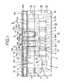
- the additional rail units C are provided between a work piece feeding unit A and a product accommodating unit B.
- the additional rail units C can be disconnected from the units A and B.
- the work piece feeding unit A, the product accommodating unit B and the additional rail units C respectively have base sections and rail sections.
- Many kinds of functional sections e.g., a feeding section, a transferring section, a pick-up section, a degating section, an accommodating section, a press section, a film unit, can be provided on the base sections.
- the work piece feeding unit A arranges and feeds work pieces, e.g., lead frames accommodated in feeding magazines 2, plastic substrates, which are located at a work piece feeding section 1, to a turn table 3.
- the work pieces are further conveyed to a transferring section 4 by a proper conveying mechanism (not shown).
- a heater for heating the substrates may be provided to the transferring section 4.
- a resin feeding section 5 sets resin tablets, which are sent by a linear feeder (not shown), in tablet holders 6 and conveys the tablet holders 6 to the transferring section.
- a press unit 7 comprises a molding die 8, a clamping mechanism for opening and closing the molding die 8, a transfer mechanism for sending molten resin to a cavity of the molding die with pressure, etc..
- the press unit 7 is provided on the base section 9.
- a film unit F which is capable of feeding release film 10, is attached to the molding die 8. Note that, press units may be provided to the product accommodating unit B and the additional rail units C, and the film units F may be attached to the additional press units.
- Each film unit F comprises a film feeding section 11, which is provided on one side of the press unit 7, and a film collecting section 12, which is provided on the other side of the press unit 7.
- the release film 10 is fed or extended, from the film feeding section 11 to the film collecting section 12, in the direction perpendicular to the rail sections 13, 26 and 28. They contain release film 10 which is used so as to mold, for example, QFNs in which parts of leads are projected from package sections, and BGAs, in which connecting portions, which will be connected to terminals, e.g., bumps, solder balls, are exposed.
- the release film 10 is capable of resisting heat of the molding die 8, easily peeling off from the molding die 8 and having enough softness and extensivity.
- the release film 10 is made from, e.g., PTFE, ETFE, PET, FEP, glass cloth including fluorine, polypropylene, polyvinylidene chloride.
- the release film 10 is fixed on a parting face of the molding die 8 by sucking air through sucking holes bored in the parting face.
- the film units F are further explained later. In the case of feeding the work pieces from outside, the feeding section and the arranging section of the work piece feeding unit A may be omitted.
- the rail section 13 is the common rail section.
- a loader 14, which takes the resin tablets from the tablet holders 6, and an unloader 15, which takes out the products from the press unit 7, are moved on the common rail section 13.
- the loader 14 and the unloader 15 are moved on the common rail section 13 and capable of moving into and away from the press unit 7, etc..
- extended parts 13a are formed at one end (the right end in Fig. 1 ) of the common rail section 13; cut parts 13b are formed at the other end (the left end in Fig. 1 ) of the common rail section 13.
- a sucking duct 16 is provided to the common rail section 13 and capable of connecting to a sucking duct of the unloader 15.
- One end of the duct 16 is connected to a vacuum unit 17; a connector 16a is provided to the other end of the duct 16.
- a sucking duct 30 of the additional rail unit C can be connected to the connector 16a.
- a symbol 18 stands for a product take-out section.
- the molded products which are taken out from one of the press units, are transferred to a moving table 19, which is located under the product take-out section 18.
- the unloader 15 moves to take out next products.
- the moving table 19 holds and conveys the products to a degating section 20.
- the degating section 20 presses and cools the products, which have been conveyed by the moving table 19, and removes disused resin by twisting the products.
- the disused resin, which have been removed from the products are accommodated in a scrap box (not shown).
- the moving table 19 further conveys the products, from which the disused resin is removed, to an accommodating section 21.
- the products on the moving table 19 are once picked up by a pick-up 22.
- the moving table 19 returns to the product take-out section 18.
- the pick-up 22 arranges and accommodates the products into accommodating magazines 23.
- the unloader 15 has no gate-breaking mechanism and no cooling mechanism, so the unloader 15 can move to take out the next products soon after transferring the products at the product take-out section 18. Therefore, the products can be taken out and transferred in a short time.
- a press unit 24 is provided on a base section 25.
- the press unit 7 comprises a molding die 8, a clamping mechanism for opening and closing the molding die 8, a transfer mechanism for sending molten resin to a cavity of the molding die with pressure, etc..
- the degating section and the accommodating section of the product accommodating unit B may be omitted.
- the rail section 26 is the common rail section.
- the loader 14, which takes the work pieces and the resin tablets to the press unit 24, and the unloader 15, which takes out the products from the press unit 24, are moved on the common rail section 26.
- extended parts 26a are formed at one end (the right end in Fig. 1 ) of the common rail section 26; cut parts 26b are formed at the other end (the left end in Fig. 1 ) of the common rail section 26.
- a sucking duct 27 is provided to the common rail section 26.
- One end of the duct 27 is connected to a connector 30a of a duct 30 of the additional rail unit C; the other end of the duct 27 has a connector 27a.
- the duct of the unloader 15 is connected to a connecting hole (not shown) of the connector 27a of the duct 27. While the unloader 15 moves into and away from the molding die 8, which are opened, the unloader 15 cleans the parting faces of the molding die, and resin dusts are sucked and collected by the vacuum unit 17, which is provided to the work piece feeding unit A.
- the additional rail units C are detachably attached between the work piece feeding unit A and the product accommodating unit B.
- Rail sections 28 are respectively provided to the additional rail units C.
- the rail sections 28 are connected to the rail sections 13 and 26.
- the loader 14 and the unloader 15 can move on the rail sections 13 and 26, too. Namely, the loader 14 and the unloader 15 can continuously move on the rail sections 13, 26 and 28.
- Extended parts 28a are formed at one end of each rail section 28, and cut parts 26b are formed at the other end of each rail section 28 as well as the common rail sections 13 and 26.
- Each of base sections 29 supports the rail section 28 and many kinds of the functional sections, e.g., the press unit 31, the film unit F.
- the additional rail units C are provided between the work piece feeding unit A and the product accommodating unit B, and the rail sections 13, 26 and 28 are connected.
- the base sections 9 and 29, the base sections 29 and 29 and the base sections 29 and 25 are mutually connected by bolts. Note that, the additional rail units C can be exchanged to other additional rail units, but the functional sections of the additional rail units C may be exchanged to other functional sections.
- Each of the additional rail units C has a duct 30, whose one end has a connector 30a capable of connecting to the duct of the unloader 15.
- the ducts 30 are connected to the ducts 16 and 27, which are respectively provided to the rail sections 13 and 26, by the connectors 16a and 30a, so that the ducts 30 are connected to the vacuum unit 17.
- two additional rail units C are added between the work piece feeding unit A and the product accommodating unit B.
- the extended parts 13a and the cut parts 28b are fitted, so that the rail sections 13 and 28 are connected.
- the connector 16a of the duct 16 is connected to one end of the duct 30, so that the work piece feeding unit A and the additional rail unit C are connected.
- the extended parts 28a and the cut parts 26b are fitted, so that the rail sections 26 and 28 are connected.
- the connector 30a of the duct 30 is connected to one end of the duct 27, so that the additional rail unit C and the product accommodating unit B are connected.
- the extended parts 28a of one of the rail section 28 (the left rail section 28 in Fig.
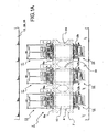
- Fig. 1A shows arrangement of the film units F.
- Three press units 7, 24 and 31 are arranged side by side.
- the film units F are respectively detachably attached to the press units 7, 24 and 31.
- the film unit is attached to at least one of the press units.
- Each film unit F has the film feeding section 11, which is located on one side of the press unit, and the film collecting section 12, which is located on the other side of the press unit.
- the film feeding section 11 of each film unit F is capable of moving, on the rail sections 13, 28 and 26, away from an upper fixed platen 8a. Therefore, the film feeding section 11 can be drawn outward.
- the film collecting section 12 of each film unit F is capable of turning, with respect to the upper fixed platen 8a, about a shaft 12c.
- the film feeding section 11 includes: a film feeding roller 11c, on which the release film 10 is wound; and a tension roller 11d capable of giving fixed tension to the release film 10 drawn from the film feeding roller 11c.
- the film collecting section 12 includes: a film collecting roller 12c which winds the release film 10 used; and a tension roller 12d capable of giving fixed tension to the release film 10 collected by the film collecting roller 12c.
- the tension rollers 11d and 12d have sensors 11e and 12e, which respectively detect revolution numbers (rotational speed) of the tension rollers 11d and 12d.
- the revolution numbers of motors 42 and 43, which respectively rotate the tension rollers 11d and 12d, are controlled on the basis of output signals of the sensors 11e and 12e. Note that, one of the sensors 11e and 12e may be omitted. In the present embodiment, even if diameters of the film rolls are changed, the release film 10 can be stably supplied with fixed feeding length and fixed tension.
- the film feeding section 11 has two guide rollers 44; the film collecting section 12 has two guide rollers 45.
- the guide rollers 44 and 45 move the release film 10 away from the parting face of the molding die 8.
- the guide rollers 44 and 45 can be moved, by cylinder units 46 and 47, in the vertical direction, so that the release film 10 can be moved to and away from the parting face.
- the release film 10 is fed a prescribed length, the release film 10 is moved away from the parting face by the cylinder units 46 and 47, so that the release film 10 can be smoothly fed without damaging the release film 10. Therefore, the used release film 10 can be reused.
- the film feeding section 11 is located on inner side, a working space for exchanging the film roll is narrow. To solve the problem, the film feeding section 11 can be drawn outward via a vacant space above the rail sections 13, 26 and 28. This structure will be explained with reference to Figs. 3-6 .
- the film feeding section 11 is detachably attached to the upper fixed platen 8a with an attaching plate 48.
- One ends of rail rods 49 are respectively fixed to ends of the attaching plate 48; the other ends of the rail rods 49 are fixed to a rod plate 50.
- Holder plates 51 are slidably connected to the rail rods 49, and a connecting shaft 52 is spanned between the holder plates 51.
- a film holding plate 53 is connected to the connecting shaft 52.
- the film feeding roller 11c and the motor 42 are attached to the film holding plate 53 (see Fig. 2A ).
- a rod plate 54 is connected to the connecting shaft 52.
- a rod 55 is pierced through the rod plate 54, and a screw section of the rod 55 is screwed with the rod plate 54.
- the end of the screw section of the rod 55 is also screwed with the attaching plate 48.
- the other end of the rod 55 is pierced through a plate 50, and a handle 56 is attached to the other end of the rod 55. By rotating the handle 56, the one end of the rod 55 can be connected to and disconnected from the attaching plate 48.
- the plates 51 and 53 which are connected by the plate 54 and the shaft 52, are slid on the rail rods 49, so that the film feeding section 11 can be drawn beyond the rail section.
- a moving range of the plate 51 is limited when a part of the plate 53 contacts the plate 50.
- the plates 51 are fixed to the shaft 52 by keys 57 so as not to rotate.
- a movable plate 58 is spanned between lower ends of the plates 51.
- the cylinder unit 46 is fixed to a center part of the movable plate 58; guide rods 59 are respectively fixed to both ends of the movable plate 58.
- a front end of a cylinder rod of the cylinder unit 46 is connected to a horizontal plate 60.
- the horizontal plate 60 is moved in the vertical direction.
- One end of a bolt 61 is fixed to the movable plate 58; the other end of the bolt 61 is pierced through the horizontal plate 60.
- a moving range of the horizontal plate 60 can be changed by changing a distance between stopper nuts 62, which are screwed with the bolt 61.
- Roller plates 63 which are extended in the vertical direction, are respectively provided to both ends of the horizontal plate 60.
- the guide roller 44 is rotatably spanned between the roller plate 63.
- An ion blower 64 which blows ion to remove static electricity from the release film 10, is provided to the roller plates 63. Therefore, problems caused by the static electricity in the release film 10 can be prevented.
- wire guides 65 which guide wires and tubes without twisting each other, are provided to the movable plate 51.
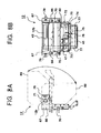
- the film collecting section 12 is detachably attached to the upper fixed platen 8a with an attaching plate 66. Plates 67 are respectively extended from both sides of the attaching plate 66. A shaft 12b is spanned between the plates 67. As shown in Fig. 8B , a film plate 69 is connected to the shaft 12b. The film collecting roller 12c and the motor 43 are attached to the film plate 69.
- fixed plates 70 are respectively connected to both ends of the shaft 12b and located close to the plates 67.
- the fixed plates 70 are fixed to the shaft 12b by keys 71 so as not to rotate.
- a plate 72 is spanned between lower ends of the fixed plates 70.
- the cylinder unit 47 is fixed to a center part of the plate 72; guide rods 73 are respectively fixed to both ends of the plate 72.
- a front end of a cylinder rod of the cylinder unit 47 is connected to a horizontal plate 74.
- the horizontal plate 74 is moved in the vertical direction.
- One end of a bolt 75 is fixed to the plate 72; the other end of the bolt 75 is pierced through the horizontal plate 74.
- a moving range of the horizontal plate 74 can be changed by changing a distance between stopper nuts 76, which are screwed with the bolt 75.
- Roller plates 77 which are extended in the vertical direction, are respectively provided to both ends of the horizontal plate 74.
- the guide roller 45 is rotatably spanned between the roller plate 77.
- Screws 78 are pierced through the plates 67 and screwed with the fixed plates 70, so that the fixed plates 70, which are connected to the shaft 12b, are respectively fixed to the plates 67.
- the film plate 69 and the fixed plates 70 can be turn 90 ° about the shaft 12b, as shown by two-dot chain lines in Fig. 8A , by detaching the screws 78.
- the film feeding section 12 can be fixed at the turned position by attaching the screws 78 to the plates 67. While the film feeding section 25 is located at the turned position, the film collecting roller 12c, on which the used release film 10 has been collected, can be efficiently exchanged in a wide working space.
- the film collecting section 12 or the film feeding section 11 is capable of turning with respect to the press unit, a chase of the molding die 8 can be easily drawn outward without interfering other members.
- the film feeding section 11 can be moved away from the press unit and drawn outward, so that the space for exchanging the film feeding roller 11c can be formed and the film feeding roller 11c can be efficiently exchanged therein.
- the film feeding section 11 can be drawn via the space, in which the loader 14 and the unloader 15 are moved, without interfering the rail sections, so that the resin molding machine can be compact in size. Since the film collecting section 12 can be turned about the shaft 12b, the working space can be formed and the film collecting roller 12c, on which the used release film 10 has been collected, can be easily exchanged therein.
- the tension rollers 11d and 12d of the film feeding section 11 and the film collecting section 12 respectively have the sensors 11e and 12e so as to detect revolution numbers of the tension rollers 11d and 12d, and speed of the motors 42 and 43 are controlled on the basis of output signals of the sensors 11e and 12e. Therefore, the release film 10 can be stably supplied with fixed feeding length and fixed tension. Note that, the control can be executed by one of the sensors 11e and 12e.
- the film feeding section 11 and the film collecting section 12 have the guide rollers 44 and 45 capable of moving the release film 10 to and away from the parting face, so that the release film 10 can be smoothly fed without damaging the release film 10. Therefore, the used release film 10 can be reused.
- the film feeding section 11 and the film collecting section 12 may be inversely arranged with respect to the press unit. In this case, the film collecting section 12 may be moved beyond the rail sections, and the film feeding section 11 may be turned about a shaft.
- a hinge may be provided to the attaching plate 48 or 66 instead of the shaft 12b, and the film feeding section 11 or the film collecting section 12 may be turned about the hinge.
- the hinge or hinges are provided to one or both ends of the attaching plate 66. With this structure, the film collecting roller 12c can be turned 90°.
- the film feeding section 11 and the film collecting section 12 can be drawn or turned. Further, the both sections 11 and 12 may be drawn or turned, and the both sections 11 and 12 may be turned and drawn. In the present embodiment, the drawing direction is perpendicular to the rail sections, but it may diagonally cross the rail sections.
- the film unit F may be employed in the resin molding machine, in which the work piece feeding unit A and the product accommodating unit B are integrated.
Landscapes
- Engineering & Computer Science (AREA)
- Mechanical Engineering (AREA)
- Manufacturing & Machinery (AREA)
- Robotics (AREA)
- Encapsulation Of And Coatings For Semiconductor Or Solid State Devices (AREA)
- Injection Moulding Of Plastics Or The Like (AREA)
- Moulds For Moulding Plastics Or The Like (AREA)
- Processing And Handling Of Plastics And Other Materials For Molding In General (AREA)
Claims (5)
- Machine de moulage de résine,
comprenant:une unité d'amenée de pièce (A);une unité de réception de produit (B);une unité de presse (7, 24, 31) pour le moulage d'une pièce;un chargeur (14) pour convoyer la pièce et la résine pour le moulage de ladite unité d'amenée de pièce (A) à ladite unité de presse (7, 24, 31);un déchargeur (15) pour convoyer un produit moulé de ladite unité de presse (7, 24, 31) à ladite unité de réception de produit (B); etune section d'amenée de film (11) pour amener un film anti-adhésif (10) sur une face de séparation de ladite unité de presse (7, 24, 31), ladite section d'amenée de film (11) étant réalisée sur un côté de ladite unité de presse (7, 24, 31); etune section de collecte de film (12) pour collecter le film anti-adhésif usé (10), ladite section de collecte de film (12) étant réalisée sur l'autre côté de ladite unité de presse (7, 24, 31), caractérisée en ce que ladite section d'amenée de film (11) et/ou ladite section de collecte de film (12) peut être tournée ou déplacée horizontalement par rapport à ladite unité de presse (7, 24, 31) de façon à s'éloigner de ladite unité de presse (7, 24, 31) pour le remplacement d'un rouleau du film anti-adhésif (10). - Machine de moulage de résine selon la revendication 1, comprenant en outre une section de rail commune (13, 26) sur laquelle ledit chargeur (14) et ledit déchargeur (15) sont déplacés, ladite section de rail commune (13, 26) étant réalisée sur le côté intérieur par rapport à ladite unité de presse (7, 24, 31),
où une parmi ladite section d'amenée de film (11) et ladite section de collecte de film (12), qui se situe sur l'autre côté par rapport à ladite unité de presse (7, 24, 31), peut être tournée, et l'autre, qui se situe sur le côté intérieur par rapport à celle-ci, peut être déplacée horizontalement dans la direction croisant ladite section de rail commune (13, 26). - Machine de moulage de résine selon la revendication 1, dans laquelle ladite section d'amenée de film (11) comprend: un rouleau d'amenée de film (11c), sur lequel le film anti-adhésif (10) est enroulé; et un premier rouleau tendeur (11d) apte à conférer une tension au film anti-adhésif (10) retiré du rouleau d'amenée de film (11c), et
ladite section de collecte de film (12) comprend: un rouleau de collecte de film (12c) qui enroule le film anti-adhésif (10) utilisé; et un deuxième rouleau tendeur (12d) apte à conférer une tension au film anti-adhésif (10) collecté par le rouleau de collecte de film (12d). - Machine de moulage de résine selon la revendication 3, dans laquelle les premier et second rouleaux tendeurs (11d, 12d) de ladite section d'amenée de film (11) et de ladite section de collecte de film (12) ont respectivement des capteurs qui détectent respectivement des nombres de tours des premier et second rouleaux tendeurs (11d, 12d), et
les nombres de tours de sources d'entraînement (42, 43) qui font tourner respectivement lesdits rouleaux tendeurs (11d, 12d) sont commandés sur la base de signaux de sortie des capteurs. - Machine de moulage de résine selon la revendication 1, dans laquelle ladite section d'amenée de film (11) et ladite section de collecte de film (12) comportent respectivement des rouleaux de guidage (44, 45) pour déplacer le film anti-adhésif (10) au loin de la face de séparation de ladite unité de presse (7, 24, 31).
Applications Claiming Priority (7)
| Application Number | Priority Date | Filing Date | Title |
|---|---|---|---|
| JP2000121017A JP4327985B2 (ja) | 2000-04-21 | 2000-04-21 | 樹脂封止装置 |
| JP2000120997 | 2000-04-21 | ||
| JP2000120997A JP4347991B2 (ja) | 2000-04-21 | 2000-04-21 | 樹脂封止装置 |
| JP2000121017 | 2000-04-21 | ||
| JP2000122911A JP4327988B2 (ja) | 2000-04-24 | 2000-04-24 | 樹脂タブレット送り装置及び樹脂封止装置 |
| JP2000122911 | 2000-04-24 | ||
| EP01303591A EP1147870B1 (fr) | 2000-04-21 | 2001-04-19 | Machine pour le moulage de résine |
Related Parent Applications (2)
| Application Number | Title | Priority Date | Filing Date |
|---|---|---|---|
| EP01303591.0 Division | 2001-04-19 | ||
| EP01303591A Division EP1147870B1 (fr) | 2000-04-21 | 2001-04-19 | Machine pour le moulage de résine |
Publications (2)
| Publication Number | Publication Date |
|---|---|
| EP1514662A1 EP1514662A1 (fr) | 2005-03-16 |
| EP1514662B1 true EP1514662B1 (fr) | 2011-03-02 |
Family
ID=27343164
Family Applications (2)
| Application Number | Title | Priority Date | Filing Date |
|---|---|---|---|
| EP01303591A Expired - Lifetime EP1147870B1 (fr) | 2000-04-21 | 2001-04-19 | Machine pour le moulage de résine |
| EP04029271A Expired - Lifetime EP1514662B1 (fr) | 2000-04-21 | 2001-04-19 | Machine pour le moulage de résine |
Family Applications Before (1)
| Application Number | Title | Priority Date | Filing Date |
|---|---|---|---|
| EP01303591A Expired - Lifetime EP1147870B1 (fr) | 2000-04-21 | 2001-04-19 | Machine pour le moulage de résine |
Country Status (7)
| Country | Link |
|---|---|
| US (1) | US6814556B2 (fr) |
| EP (2) | EP1147870B1 (fr) |
| KR (1) | KR100427519B1 (fr) |
| CN (2) | CN1199776C (fr) |
| DE (2) | DE60132127D1 (fr) |
| SG (1) | SG89391A1 (fr) |
| TW (1) | TW509615B (fr) |
Families Citing this family (18)
| Publication number | Priority date | Publication date | Assignee | Title |
|---|---|---|---|---|
| JP3609824B1 (ja) * | 2003-10-30 | 2005-01-12 | 第一精工株式会社 | 樹脂封止成形装置 |
| US7241414B2 (en) * | 2004-06-25 | 2007-07-10 | Asm Technology Singapore Pte Ltd. | Method and apparatus for molding a semiconductor device |
| US20070176326A1 (en) * | 2006-02-01 | 2007-08-02 | Fa-Shen Chen | Method for filling polymer blanks into molds and an apparatus thereof |
| JP2007251094A (ja) * | 2006-03-20 | 2007-09-27 | Towa Corp | 半導体チップの樹脂封止成形装置 |
| KR101446268B1 (ko) * | 2008-07-28 | 2014-10-02 | 한미반도체 주식회사 | 오토몰드장치 및 오토몰드용 클리닝장치 |
| KR20120046633A (ko) * | 2010-11-02 | 2012-05-10 | 삼성전자주식회사 | 반도체 패키지 몰딩 시스템 및 몰딩 방법 |
| TWI523164B (zh) * | 2010-11-25 | 2016-02-21 | 山田尖端科技股份有限公司 | 樹脂模塑裝置 |
| JP5342576B2 (ja) * | 2011-02-18 | 2013-11-13 | 株式会社日本製鋼所 | 旋回可能な下ユニットを備えた転写フィルム送り装置 |
| JP5866398B2 (ja) * | 2013-05-15 | 2016-02-17 | 東芝機械株式会社 | 成形システム及び成形品の製造方法 |
| CN105818337B (zh) * | 2016-04-29 | 2018-09-28 | 浙江品创知识产权服务有限公司 | 一种新型蓄电池外壳注塑模具 |
| JP6212609B1 (ja) * | 2016-08-19 | 2017-10-11 | Towa株式会社 | 樹脂成形装置及び樹脂成形品製造方法 |
| CN107521052B (zh) * | 2017-08-23 | 2023-10-03 | 歌尔科技有限公司 | 去静电分腔机构及小型注塑件取出方法 |
| CN110497577A (zh) * | 2019-08-21 | 2019-11-26 | 苏州旭芯翔智能设备有限公司 | 一种半导体元器件封装自动化注塑系统及其工作方法 |
| JP7175869B2 (ja) * | 2019-10-03 | 2022-11-21 | Towa株式会社 | 樹脂成形装置および樹脂成形方法 |
| JP7475232B2 (ja) * | 2020-07-22 | 2024-04-26 | 株式会社ディスコ | 保護部材形成装置 |
| JP7135186B1 (ja) * | 2021-09-15 | 2022-09-12 | Towa株式会社 | 樹脂供給装置、樹脂成形システム、及び、樹脂成形品の製造方法 |
| JP7813208B2 (ja) * | 2022-09-21 | 2026-02-12 | Towa株式会社 | 樹脂供給装置、樹脂成形装置、及び樹脂成形品の製造方法 |
| CN117549483B (zh) * | 2023-10-20 | 2024-04-05 | 广东百赞智能装备有限公司 | 一种侧射立压式注塑机 |
Family Cites Families (25)
| Publication number | Priority date | Publication date | Assignee | Title |
|---|---|---|---|---|
| US3797103A (en) * | 1970-05-04 | 1974-03-19 | Gen Electric | Machine and process for semiconductor device assembly |
| JPH01186638A (ja) * | 1988-01-14 | 1989-07-26 | Seiei Kosan Kk | 自動モールディング装置 |
| JPH0618219B2 (ja) * | 1988-09-27 | 1994-03-09 | 株式会社東芝 | 半導体装置の樹脂封止用樹脂タブレット供給装置 |
| JPH03262620A (ja) * | 1990-03-14 | 1991-11-22 | Japan Steel Works Ltd:The | 射出成形設備における製品搬送制御装置及びその方法 |
| JP2744324B2 (ja) | 1990-04-03 | 1998-04-28 | アピックヤマダ株式会社 | 樹脂タブレットの整列方法および整列装置 |
| JPH05138681A (ja) | 1991-11-18 | 1993-06-08 | Fujitsu Miyagi Electron:Kk | 振動式パーツフイーダ及び樹脂成形装置 |
| AU3904393A (en) * | 1992-04-13 | 1993-11-18 | Apic Yamada Corporation | Method of transfer mold and apparatus for transfer mold |
| JPH06166049A (ja) | 1992-12-01 | 1994-06-14 | Apic Yamada Kk | 樹脂タブレットの供給装置 |
| JP2555517B2 (ja) * | 1992-09-16 | 1996-11-20 | 禧夫 盛合 | 埋設構造物の形状測定方法および装置 |
| JP3286817B2 (ja) | 1993-01-28 | 2002-05-27 | 松下電器産業株式会社 | 多室型空気調和装置 |
| US6007316A (en) * | 1993-07-22 | 1999-12-28 | Towa Corporation | Apparatus for molding resin to seal electronic parts |
| JP2932136B2 (ja) * | 1993-07-22 | 1999-08-09 | トーワ株式会社 | 電子部品の樹脂封止成形方法及び装置 |
| TW257745B (fr) * | 1993-07-22 | 1995-09-21 | Towa Kk | |
| NL9401930A (nl) * | 1994-11-18 | 1996-07-01 | Fico Bv | Modulaire omhulinrichting. |
| EP0759349B1 (fr) * | 1995-08-23 | 2002-06-05 | Apic Yamada Corporation | Machine de moulage automatique avec film de démoulage |
| NL1003366C2 (nl) * | 1996-06-18 | 1997-12-19 | Fico Bv | Inrichting en werkwijze voor het omhullen van produkten. |
| JP2820125B2 (ja) | 1996-07-04 | 1998-11-05 | 日本電気株式会社 | タブレット供給装置 |
| JP3642637B2 (ja) | 1996-08-20 | 2005-04-27 | アピックヤマダ株式会社 | 樹脂モールド装置 |
| TW410194B (en) * | 1996-08-20 | 2000-11-01 | Apic Yamada Kk | Resin molding machine |
| JP3776174B2 (ja) * | 1996-09-12 | 2006-05-17 | アピックヤマダ株式会社 | 半導体部品の搬送装置 |
| JP3809233B2 (ja) * | 1996-10-15 | 2006-08-16 | アピックヤマダ株式会社 | リリースフィルムを用いる樹脂モールド装置 |
| JP4127323B2 (ja) * | 1997-01-29 | 2008-07-30 | イェス トゥガールド グラム | 組立物品の成型方法 |
| US5925384A (en) * | 1997-04-25 | 1999-07-20 | Micron Technology, Inc. | Manual pellet loader for Boschman automolds |
| JP3017470B2 (ja) * | 1997-07-11 | 2000-03-06 | アピックヤマダ株式会社 | 樹脂モールド方法及び樹脂モールド装置 |
| JP2000049175A (ja) * | 1998-07-31 | 2000-02-18 | Tsukuba Seiko Kk | 半導体の封止成形方法及び装置 |
-
2001
- 2001-04-17 TW TW090109113A patent/TW509615B/zh not_active IP Right Cessation
- 2001-04-19 DE DE60132127T patent/DE60132127D1/de not_active Expired - Lifetime
- 2001-04-19 EP EP01303591A patent/EP1147870B1/fr not_active Expired - Lifetime
- 2001-04-19 EP EP04029271A patent/EP1514662B1/fr not_active Expired - Lifetime
- 2001-04-19 DE DE60144161T patent/DE60144161D1/de not_active Expired - Lifetime
- 2001-04-20 US US09/838,240 patent/US6814556B2/en not_active Expired - Lifetime
- 2001-04-20 CN CNB011214287A patent/CN1199776C/zh not_active Expired - Lifetime
- 2001-04-20 KR KR10-2001-0021377A patent/KR100427519B1/ko not_active Expired - Lifetime
- 2001-04-20 CN CNB2004100956825A patent/CN100363166C/zh not_active Expired - Lifetime
- 2001-04-20 SG SG200102217A patent/SG89391A1/en unknown
Also Published As
| Publication number | Publication date |
|---|---|
| EP1514662A1 (fr) | 2005-03-16 |
| SG89391A1 (en) | 2002-06-18 |
| TW509615B (en) | 2002-11-11 |
| CN100363166C (zh) | 2008-01-23 |
| CN1644347A (zh) | 2005-07-27 |
| US20010033876A1 (en) | 2001-10-25 |
| EP1147870A2 (fr) | 2001-10-24 |
| KR20010098773A (ko) | 2001-11-08 |
| CN1335222A (zh) | 2002-02-13 |
| KR100427519B1 (ko) | 2004-04-27 |
| US6814556B2 (en) | 2004-11-09 |
| CN1199776C (zh) | 2005-05-04 |
| DE60132127D1 (de) | 2008-02-14 |
| EP1147870B1 (fr) | 2008-01-02 |
| DE60144161D1 (de) | 2011-04-14 |
| EP1147870A3 (fr) | 2002-12-04 |
Similar Documents
| Publication | Publication Date | Title |
|---|---|---|
| US6814556B2 (en) | Resin molding machine and resin tablet feeding machine | |
| EP0759349B1 (fr) | Machine de moulage automatique avec film de démoulage | |
| CN1082425C (zh) | 注射模制设备和方法 | |
| KR100257957B1 (ko) | 수지 성형 장치 | |
| KR100353341B1 (ko) | 리이드프레임성형장치 | |
| GB2280141A (en) | Method and apparatus for resin transfer encapsulation of electronic components | |
| JP3642637B2 (ja) | 樹脂モールド装置 | |
| JP4327986B2 (ja) | 樹脂封止装置 | |
| JP4327985B2 (ja) | 樹脂封止装置 | |
| JPH1058457A5 (fr) | ||
| JP3714765B2 (ja) | プレス装置の搬送機構 | |
| CN219944443U (zh) | 可多机并联的自动切筋成型设备 | |
| JP2004266153A (ja) | 樹脂封止成形装置 | |
| JP5274849B2 (ja) | 樹脂成形装置 | |
| JP4370041B2 (ja) | 樹脂タブレット供給装置及び樹脂封止装置 | |
| CN216992802U (zh) | 一种注塑组装一体机 | |
| JP4347991B2 (ja) | 樹脂封止装置 | |
| JP4078231B2 (ja) | 成形品収納装置及び樹脂封止装置 | |
| JP4347932B2 (ja) | 樹脂封止装置 | |
| US20230113479A1 (en) | Injection Molding System | |
| CN223644112U (zh) | 用于隐形眼镜的随线作业单元 | |
| CN113427705B (zh) | 一种注塑组装一体机 | |
| JP3847143B2 (ja) | 中空成形機 | |
| JP2000049175A (ja) | 半導体の封止成形方法及び装置 | |
| JP3200211B2 (ja) | 半導体封止装置 |
Legal Events
| Date | Code | Title | Description |
|---|---|---|---|
| PUAI | Public reference made under article 153(3) epc to a published international application that has entered the european phase |
Free format text: ORIGINAL CODE: 0009012 |
|
| AC | Divisional application: reference to earlier application |
Ref document number: 1147870 Country of ref document: EP Kind code of ref document: P |
|
| AK | Designated contracting states |
Kind code of ref document: A1 Designated state(s): CH DE FR GB IE LI NL |
|
| 17P | Request for examination filed |
Effective date: 20050906 |
|
| AKX | Designation fees paid |
Designated state(s): CH DE FR GB IE LI NL |
|
| 17Q | First examination report despatched |
Effective date: 20080218 |
|
| RTI1 | Title (correction) |
Free format text: RESIN MOLDING MACHINE |
|
| GRAP | Despatch of communication of intention to grant a patent |
Free format text: ORIGINAL CODE: EPIDOSNIGR1 |
|
| GRAC | Information related to communication of intention to grant a patent modified |
Free format text: ORIGINAL CODE: EPIDOSCIGR1 |
|
| GRAC | Information related to communication of intention to grant a patent modified |
Free format text: ORIGINAL CODE: EPIDOSCIGR1 |
|
| GRAS | Grant fee paid |
Free format text: ORIGINAL CODE: EPIDOSNIGR3 |
|
| GRAA | (expected) grant |
Free format text: ORIGINAL CODE: 0009210 |
|
| AC | Divisional application: reference to earlier application |
Ref document number: 1147870 Country of ref document: EP Kind code of ref document: P |
|
| AK | Designated contracting states |
Kind code of ref document: B1 Designated state(s): CH DE FR GB IE LI NL |
|
| REG | Reference to a national code |
Ref country code: GB Ref legal event code: FG4D |
|
| REG | Reference to a national code |
Ref country code: CH Ref legal event code: EP |
|
| REG | Reference to a national code |
Ref country code: IE Ref legal event code: FG4D |
|
| REF | Corresponds to: |
Ref document number: 60144161 Country of ref document: DE Date of ref document: 20110414 Kind code of ref document: P |
|
| REG | Reference to a national code |
Ref country code: DE Ref legal event code: R096 Ref document number: 60144161 Country of ref document: DE Effective date: 20110414 |
|
| REG | Reference to a national code |
Ref country code: NL Ref legal event code: T3 |
|
| REG | Reference to a national code |
Ref country code: CH Ref legal event code: PL |
|
| PLBE | No opposition filed within time limit |
Free format text: ORIGINAL CODE: 0009261 |
|
| STAA | Information on the status of an ep patent application or granted ep patent |
Free format text: STATUS: NO OPPOSITION FILED WITHIN TIME LIMIT |
|
| REG | Reference to a national code |
Ref country code: FR Ref legal event code: ST Effective date: 20111230 |
|
| PG25 | Lapsed in a contracting state [announced via postgrant information from national office to epo] |
Ref country code: DE Free format text: LAPSE BECAUSE OF NON-PAYMENT OF DUE FEES Effective date: 20111101 Ref country code: FR Free format text: LAPSE BECAUSE OF NON-PAYMENT OF DUE FEES Effective date: 20110502 Ref country code: LI Free format text: LAPSE BECAUSE OF NON-PAYMENT OF DUE FEES Effective date: 20110430 Ref country code: CH Free format text: LAPSE BECAUSE OF NON-PAYMENT OF DUE FEES Effective date: 20110430 |
|
| REG | Reference to a national code |
Ref country code: IE Ref legal event code: MM4A |
|
| 26N | No opposition filed |
Effective date: 20111205 |
|
| GBPC | Gb: european patent ceased through non-payment of renewal fee |
Effective date: 20110602 |
|
| REG | Reference to a national code |
Ref country code: DE Ref legal event code: R119 Ref document number: 60144161 Country of ref document: DE Effective date: 20111101 |
|
| PG25 | Lapsed in a contracting state [announced via postgrant information from national office to epo] |
Ref country code: IE Free format text: LAPSE BECAUSE OF NON-PAYMENT OF DUE FEES Effective date: 20110419 |
|
| PG25 | Lapsed in a contracting state [announced via postgrant information from national office to epo] |
Ref country code: GB Free format text: LAPSE BECAUSE OF NON-PAYMENT OF DUE FEES Effective date: 20110602 |
|
| PGFP | Annual fee paid to national office [announced via postgrant information from national office to epo] |
Ref country code: NL Payment date: 20200427 Year of fee payment: 20 |
|
| REG | Reference to a national code |
Ref country code: NL Ref legal event code: MK Effective date: 20210418 |