EP1516939A1 - Verfahren und vorrichtung zur herstellung eines mit schmelzflüssigem metall beschichteten stahlblechs - Google Patents
Verfahren und vorrichtung zur herstellung eines mit schmelzflüssigem metall beschichteten stahlblechs Download PDFInfo
- Publication number
- EP1516939A1 EP1516939A1 EP03738502A EP03738502A EP1516939A1 EP 1516939 A1 EP1516939 A1 EP 1516939A1 EP 03738502 A EP03738502 A EP 03738502A EP 03738502 A EP03738502 A EP 03738502A EP 1516939 A1 EP1516939 A1 EP 1516939A1
- Authority
- EP
- European Patent Office
- Prior art keywords
- steel sheet
- hot
- electromagnet
- current value
- dip metal
- Prior art date
- Legal status (The legal status is an assumption and is not a legal conclusion. Google has not performed a legal analysis and makes no representation as to the accuracy of the status listed.)
- Withdrawn
Links
- 229910000831 Steel Inorganic materials 0.000 title claims abstract description 253
- 239000010959 steel Substances 0.000 title claims abstract description 253
- 239000002184 metal Substances 0.000 title claims abstract description 74
- 229910052751 metal Inorganic materials 0.000 title claims abstract description 74
- 238000004519 manufacturing process Methods 0.000 title claims abstract description 11
- 239000011248 coating agent Substances 0.000 claims abstract description 96
- 238000000576 coating method Methods 0.000 claims abstract description 96
- 238000000034 method Methods 0.000 claims abstract description 25
- 238000011144 upstream manufacturing Methods 0.000 claims abstract description 8
- 230000007547 defect Effects 0.000 description 17
- 238000009826 distribution Methods 0.000 description 10
- 230000007935 neutral effect Effects 0.000 description 9
- 229910001335 Galvanized steel Inorganic materials 0.000 description 8
- 239000008397 galvanized steel Substances 0.000 description 8
- 230000000052 comparative effect Effects 0.000 description 7
- 238000012937 correction Methods 0.000 description 7
- 238000006073 displacement reaction Methods 0.000 description 7
- 238000011084 recovery Methods 0.000 description 7
- 238000013016 damping Methods 0.000 description 4
- 238000010586 diagram Methods 0.000 description 4
- 230000000694 effects Effects 0.000 description 4
- 230000003247 decreasing effect Effects 0.000 description 3
- 238000005246 galvanizing Methods 0.000 description 3
- HCHKCACWOHOZIP-UHFFFAOYSA-N Zinc Chemical compound [Zn] HCHKCACWOHOZIP-UHFFFAOYSA-N 0.000 description 2
- 238000005452 bending Methods 0.000 description 2
- 230000007423 decrease Effects 0.000 description 2
- 238000011156 evaluation Methods 0.000 description 2
- 230000002265 prevention Effects 0.000 description 2
- 230000001629 suppression Effects 0.000 description 2
- 229910052725 zinc Inorganic materials 0.000 description 2
- 239000011701 zinc Substances 0.000 description 2
- DEHXEFKZGADDMS-UHFFFAOYSA-N CCCCC1CCC(CO)CC1 Chemical compound CCCCC1CCC(CO)CC1 DEHXEFKZGADDMS-UHFFFAOYSA-N 0.000 description 1
- 239000004566 building material Substances 0.000 description 1
- 239000010960 cold rolled steel Substances 0.000 description 1
- 230000007797 corrosion Effects 0.000 description 1
- 238000005260 corrosion Methods 0.000 description 1
- 238000002347 injection Methods 0.000 description 1
- 239000007924 injection Substances 0.000 description 1
- 238000009434 installation Methods 0.000 description 1
- 238000011835 investigation Methods 0.000 description 1
- 238000012423 maintenance Methods 0.000 description 1
- 238000000611 regression analysis Methods 0.000 description 1
- 238000005096 rolling process Methods 0.000 description 1
- 239000000758 substrate Substances 0.000 description 1
- 238000012360 testing method Methods 0.000 description 1
Images




Classifications
-
- C—CHEMISTRY; METALLURGY
- C23—COATING METALLIC MATERIAL; COATING MATERIAL WITH METALLIC MATERIAL; CHEMICAL SURFACE TREATMENT; DIFFUSION TREATMENT OF METALLIC MATERIAL; COATING BY VACUUM EVAPORATION, BY SPUTTERING, BY ION IMPLANTATION OR BY CHEMICAL VAPOUR DEPOSITION, IN GENERAL; INHIBITING CORROSION OF METALLIC MATERIAL OR INCRUSTATION IN GENERAL
- C23C—COATING METALLIC MATERIAL; COATING MATERIAL WITH METALLIC MATERIAL; SURFACE TREATMENT OF METALLIC MATERIAL BY DIFFUSION INTO THE SURFACE, BY CHEMICAL CONVERSION OR SUBSTITUTION; COATING BY VACUUM EVAPORATION, BY SPUTTERING, BY ION IMPLANTATION OR BY CHEMICAL VAPOUR DEPOSITION, IN GENERAL
- C23C2/00—Hot-dipping or immersion processes for applying the coating material in the molten state without affecting the shape; Apparatus therefor
- C23C2/14—Removing excess of molten coatings; Controlling or regulating the coating thickness
- C23C2/16—Removing excess of molten coatings; Controlling or regulating the coating thickness using fluids under pressure, e.g. air knives
- C23C2/18—Removing excess of molten coatings from elongated material
- C23C2/20—Strips; Plates
-
- C—CHEMISTRY; METALLURGY
- C23—COATING METALLIC MATERIAL; COATING MATERIAL WITH METALLIC MATERIAL; CHEMICAL SURFACE TREATMENT; DIFFUSION TREATMENT OF METALLIC MATERIAL; COATING BY VACUUM EVAPORATION, BY SPUTTERING, BY ION IMPLANTATION OR BY CHEMICAL VAPOUR DEPOSITION, IN GENERAL; INHIBITING CORROSION OF METALLIC MATERIAL OR INCRUSTATION IN GENERAL
- C23C—COATING METALLIC MATERIAL; COATING MATERIAL WITH METALLIC MATERIAL; SURFACE TREATMENT OF METALLIC MATERIAL BY DIFFUSION INTO THE SURFACE, BY CHEMICAL CONVERSION OR SUBSTITUTION; COATING BY VACUUM EVAPORATION, BY SPUTTERING, BY ION IMPLANTATION OR BY CHEMICAL VAPOUR DEPOSITION, IN GENERAL
- C23C2/00—Hot-dipping or immersion processes for applying the coating material in the molten state without affecting the shape; Apparatus therefor
-
- C—CHEMISTRY; METALLURGY
- C23—COATING METALLIC MATERIAL; COATING MATERIAL WITH METALLIC MATERIAL; CHEMICAL SURFACE TREATMENT; DIFFUSION TREATMENT OF METALLIC MATERIAL; COATING BY VACUUM EVAPORATION, BY SPUTTERING, BY ION IMPLANTATION OR BY CHEMICAL VAPOUR DEPOSITION, IN GENERAL; INHIBITING CORROSION OF METALLIC MATERIAL OR INCRUSTATION IN GENERAL
- C23C—COATING METALLIC MATERIAL; COATING MATERIAL WITH METALLIC MATERIAL; SURFACE TREATMENT OF METALLIC MATERIAL BY DIFFUSION INTO THE SURFACE, BY CHEMICAL CONVERSION OR SUBSTITUTION; COATING BY VACUUM EVAPORATION, BY SPUTTERING, BY ION IMPLANTATION OR BY CHEMICAL VAPOUR DEPOSITION, IN GENERAL
- C23C2/00—Hot-dipping or immersion processes for applying the coating material in the molten state without affecting the shape; Apparatus therefor
- C23C2/003—Apparatus
- C23C2/0034—Details related to elements immersed in bath
- C23C2/00342—Moving elements, e.g. pumps or mixers
- C23C2/00344—Means for moving substrates, e.g. immersed rollers or immersed bearings
-
- C—CHEMISTRY; METALLURGY
- C23—COATING METALLIC MATERIAL; COATING MATERIAL WITH METALLIC MATERIAL; CHEMICAL SURFACE TREATMENT; DIFFUSION TREATMENT OF METALLIC MATERIAL; COATING BY VACUUM EVAPORATION, BY SPUTTERING, BY ION IMPLANTATION OR BY CHEMICAL VAPOUR DEPOSITION, IN GENERAL; INHIBITING CORROSION OF METALLIC MATERIAL OR INCRUSTATION IN GENERAL
- C23C—COATING METALLIC MATERIAL; COATING MATERIAL WITH METALLIC MATERIAL; SURFACE TREATMENT OF METALLIC MATERIAL BY DIFFUSION INTO THE SURFACE, BY CHEMICAL CONVERSION OR SUBSTITUTION; COATING BY VACUUM EVAPORATION, BY SPUTTERING, BY ION IMPLANTATION OR BY CHEMICAL VAPOUR DEPOSITION, IN GENERAL
- C23C2/00—Hot-dipping or immersion processes for applying the coating material in the molten state without affecting the shape; Apparatus therefor
- C23C2/04—Hot-dipping or immersion processes for applying the coating material in the molten state without affecting the shape; Apparatus therefor characterised by the coating material
- C23C2/06—Zinc or cadmium or alloys based thereon
-
- C—CHEMISTRY; METALLURGY
- C23—COATING METALLIC MATERIAL; COATING MATERIAL WITH METALLIC MATERIAL; CHEMICAL SURFACE TREATMENT; DIFFUSION TREATMENT OF METALLIC MATERIAL; COATING BY VACUUM EVAPORATION, BY SPUTTERING, BY ION IMPLANTATION OR BY CHEMICAL VAPOUR DEPOSITION, IN GENERAL; INHIBITING CORROSION OF METALLIC MATERIAL OR INCRUSTATION IN GENERAL
- C23C—COATING METALLIC MATERIAL; COATING MATERIAL WITH METALLIC MATERIAL; SURFACE TREATMENT OF METALLIC MATERIAL BY DIFFUSION INTO THE SURFACE, BY CHEMICAL CONVERSION OR SUBSTITUTION; COATING BY VACUUM EVAPORATION, BY SPUTTERING, BY ION IMPLANTATION OR BY CHEMICAL VAPOUR DEPOSITION, IN GENERAL
- C23C2/00—Hot-dipping or immersion processes for applying the coating material in the molten state without affecting the shape; Apparatus therefor
- C23C2/14—Removing excess of molten coatings; Controlling or regulating the coating thickness
- C23C2/24—Removing excess of molten coatings; Controlling or regulating the coating thickness using magnetic or electric fields
-
- C—CHEMISTRY; METALLURGY
- C23—COATING METALLIC MATERIAL; COATING MATERIAL WITH METALLIC MATERIAL; CHEMICAL SURFACE TREATMENT; DIFFUSION TREATMENT OF METALLIC MATERIAL; COATING BY VACUUM EVAPORATION, BY SPUTTERING, BY ION IMPLANTATION OR BY CHEMICAL VAPOUR DEPOSITION, IN GENERAL; INHIBITING CORROSION OF METALLIC MATERIAL OR INCRUSTATION IN GENERAL
- C23C—COATING METALLIC MATERIAL; COATING MATERIAL WITH METALLIC MATERIAL; SURFACE TREATMENT OF METALLIC MATERIAL BY DIFFUSION INTO THE SURFACE, BY CHEMICAL CONVERSION OR SUBSTITUTION; COATING BY VACUUM EVAPORATION, BY SPUTTERING, BY ION IMPLANTATION OR BY CHEMICAL VAPOUR DEPOSITION, IN GENERAL
- C23C2/00—Hot-dipping or immersion processes for applying the coating material in the molten state without affecting the shape; Apparatus therefor
- C23C2/34—Hot-dipping or immersion processes for applying the coating material in the molten state without affecting the shape; Apparatus therefor characterised by the shape of the material to be treated
- C23C2/36—Elongated material
- C23C2/40—Plates; Strips
-
- C—CHEMISTRY; METALLURGY
- C23—COATING METALLIC MATERIAL; COATING MATERIAL WITH METALLIC MATERIAL; CHEMICAL SURFACE TREATMENT; DIFFUSION TREATMENT OF METALLIC MATERIAL; COATING BY VACUUM EVAPORATION, BY SPUTTERING, BY ION IMPLANTATION OR BY CHEMICAL VAPOUR DEPOSITION, IN GENERAL; INHIBITING CORROSION OF METALLIC MATERIAL OR INCRUSTATION IN GENERAL
- C23C—COATING METALLIC MATERIAL; COATING MATERIAL WITH METALLIC MATERIAL; SURFACE TREATMENT OF METALLIC MATERIAL BY DIFFUSION INTO THE SURFACE, BY CHEMICAL CONVERSION OR SUBSTITUTION; COATING BY VACUUM EVAPORATION, BY SPUTTERING, BY ION IMPLANTATION OR BY CHEMICAL VAPOUR DEPOSITION, IN GENERAL
- C23C2/00—Hot-dipping or immersion processes for applying the coating material in the molten state without affecting the shape; Apparatus therefor
- C23C2/50—Controlling or regulating the coating processes
- C23C2/51—Computer-controlled implementation
-
- C—CHEMISTRY; METALLURGY
- C23—COATING METALLIC MATERIAL; COATING MATERIAL WITH METALLIC MATERIAL; CHEMICAL SURFACE TREATMENT; DIFFUSION TREATMENT OF METALLIC MATERIAL; COATING BY VACUUM EVAPORATION, BY SPUTTERING, BY ION IMPLANTATION OR BY CHEMICAL VAPOUR DEPOSITION, IN GENERAL; INHIBITING CORROSION OF METALLIC MATERIAL OR INCRUSTATION IN GENERAL
- C23C—COATING METALLIC MATERIAL; COATING MATERIAL WITH METALLIC MATERIAL; SURFACE TREATMENT OF METALLIC MATERIAL BY DIFFUSION INTO THE SURFACE, BY CHEMICAL CONVERSION OR SUBSTITUTION; COATING BY VACUUM EVAPORATION, BY SPUTTERING, BY ION IMPLANTATION OR BY CHEMICAL VAPOUR DEPOSITION, IN GENERAL
- C23C2/00—Hot-dipping or immersion processes for applying the coating material in the molten state without affecting the shape; Apparatus therefor
- C23C2/50—Controlling or regulating the coating processes
- C23C2/52—Controlling or regulating the coating processes with means for measuring or sensing
- C23C2/524—Position of the substrate
Definitions
- the present invention relates to a method for producing a hot-dip metal coated steel sheet, specifically to a method of shape correction on the steel sheet using an electromagnet in non-contact state, and to an apparatus for producing thereof.
- Hot-dip metal coating represented by hot-dip galvanizing has long been practically applied.
- the hot-dip galvanized steel sheets have shown increasing demand as the plated corrosion proof steel sheets for automobiles, household electric appliances, and building materials, and face the requirement of higher quality including uniform coating weight and suppression of surface defects than ever.
- gas-wiping method is currently adopted using an apparatus shown in Fig. 1 as an example.
- a steel sheet S which is continuously immersed in a hot-dip metal coating bath 2 is drawn up vertically from the bath, and the excessive amount of molten metal adhered to the steel sheet S is removed by high pressure gas ejected from a gas-wiping device 4 positioned against each side of the steel sheet S, thus adjusting the desired coating weight.
- the steel sheet drawn up from the coating bath vibrates or generates warp in width direction thereof. Furthermore, in some cases, degraded flatness of the steel sheet occurs. If those defects occurred, the distance between the gas-wiping device and the steel sheet varies, which results in non-uniform coating weight in the longitudinal direction or the width direction of the steel sheet.
- a pair of support rolls is installed in the bath, and further a pair of similar support rolls is located above the gas-wiping device to restrict the steel sheet, thus preventing the vibration of the steel sheet and conducting the correction of warp thereon. That type of support-roll method, however, may fail to attain satisfactory effect of prevention of vibration and shape correction in some cases.
- Japanese Patent Laid-Open No. 2001-38412 discloses a damping device for damping the running steel sheet. That is, a pair of electromagnets to apply magnetic force against the steel sheet and a position sensor are mounted, thus the driving current for the electromagnet pair is controlled on the basis of the determined distance between the electromagnet and the steel sheet, and the control gain in the current control is determined on the basis of information relating to the steel sheet, such as the information of thickness, running speed, joint position, width, and tension of the steel sheet.
- a position sensor for determining the position of steel sheet is required to prevent contact of electromagnet with the steel sheet and to prevent attracting and catching the steel sheet by the electromagnet. Consequently, the method not only increases the cost but also increases the apparatus size to disturb the gas stream of the gas-wiping device, which makes the installation of electromagnets near the gas-wiping device difficult.
- the feedback control is conducted on the basis of position information supplied from the position sensor.
- the phenomenon is recognized by the position sensor, and then the current value of electromagnet is changed.
- the condition of warp may suddenly vary. In that case, the feedback control cannot respond to the sudden change of warp condition so that the warp at the front section of succeeding steel sheet cannot be corrected.
- the distance between the gas-wiping device and the steel sheet has to be widened to minimize the contact therebetween even if a warp occurred.
- the gas-wiping is requested to be done with higher gas pressure and larger gas flow rate, which makes the adjustment to a desired coating weight difficult.
- a defect flash defect
- the splash defect is a phenomenon of adhering molten metal splash to the steel sheet caused by the gas stream near the gas-wiping device.
- the method using electromagnets of the related art has problems of cost increase, insufficient effect of warp correction, and failing in producing high quality coated steel sheet.
- the object is attained by a method for producing a hot-dip metal coated steel sheet, comprising the steps of: continuously introducing a steel sheet in a hot-dip metal coating bath of a molten metal to adhere the molten metal onto a surface of the steel sheet; changing a running direction of the steel sheet using a direction-changing device located in the hot-dip metal coating bath, and then taking the steel sheet out from the bath; adjusting a coating weight of the molten metal adhered to the steel sheet using a gas-wiping device; correcting a warp appeared on the steel sheet in non-contact state by magnetic force using an electromagnet positioned at upstream side and/or downstream side of the gas-wiping device, the electromagnet applying the magnetic force to the steel sheet in the direction crossing the surface thereof; and setting a current value of electromagnet to a predetermined current value on the basis of information relating to the steel sheet.
- the method is realized by an apparatus for producing a hot-dip metal coated steel sheet, comprising: a hot-dip metal coating bath tank for adhering a molten metal onto a surface of a steel sheet; a direction-changing device located in the hot-dip metal coating bath tank to change a running direction of the steel sheet; a gas-wiping device positioned above the surface of the coating bath of the hot-dip metal coating bath tank to adjust the coating weight of the molten metal adhered to the steel sheet; an electromagnet positioned at upstream side and/or downstream side of the gas-wiping device to apply magnetic force to the steel sheet in the direction crossing the surface thereof to correct a warp appeared on the steel sheet in non-contact state; and a current value preset control device to set the current value of electromagnet to a current value preliminarily determined on the basis of information relating to the steel sheet.
- Fig. 3 shows a relation between the displacement of steel sheet and the force applied to the steel sheet, which relation was derived from the data acquired from a test apparatus simulating actual line.
- the displacement of steel sheet on the horizontal axis of Fig. 3 corresponds to the displacement X of Fig. 2.
- the attraction force of the electromagnet 5 is inversely proportional to the square of distance between the steel sheet S and the electromagnet 5, and the recovery force of the steel sheet S is proportional to the displacement X thereof.
- the curve signifying the attraction force of the electromagnet 5 and the straight line signifying the recovery force of the steel sheet S intercept to each other at two points, as shown in Fig. 3. Considering the direction of resultant force, one of these two points gives the stable neutral point, while another one gives the instable neutral point.
- the attraction force always acts stronger than the recovery force so that the steel sheet S is further attracted to become caught by the electromagnet 5.
- the steel sheet S If, however, the steel sheet S is further distant from the electromagnet 5 beyond the instable neutral point, the steel sheet S surely returns to the stable neutral point.
- the phenomena show that the warp of the steel sheet S is settled to a stable state by applying an adequate current to the electromagnet 5 to generate adequate attraction force therefrom.
- the stable neutral point is a point that the attraction force and the recovery force are balanced, and is not necessarily a point that the warp of the steel sheet S is corrected and the steel sheet s is flattened. Nevertheless, the steel sheet S can be flattened at the neutral point by optimizing the current value applied to the electromagnet 5.
- the current control of the electromagnet 5 not necessarily requires the feedback control by a position sensor, but is able to apply preset control which determines an adequate current value in advance.
- a hot-dip metal coated steel sheet is produced by a method comprising the steps of: continuously introducing the steel sheet in a hot-dip metal coating bath of a molten metal to adhere the molten metal onto a surface of the steel sheet; changing the running direction of the steel sheet using a direction-changing device located in the hot-dip metal coating bath, and then taking the steel sheet out from the bath; adjusting a coating weight of the molten metal adhered to the steel sheet using a gas-wiping device; correcting a warp appeared on the steel sheet in non-contact state by magnetic force using an electromagnet positioned at upstream side and/or downstream side of the gas-wiping device, the electromagnet applying the magnetic force to the steel sheet in the direction crossing the surface thereof; and setting a current value of electromagnet to a current value preliminarily determined on the basis of information relating to the steel sheet.
- the method suppresses the generation of warp over the whole length of the steel sheet, thereby producing a hot-
- the current value applied to the electromagnet may be changed to a current value preliminarily determined on the basis of information relating to the succeeding steel sheet.
- a shape measuring device of the steel sheet and/or a measuring device to determine the coating weight of the molten metal adhered to the steel sheet is located downstream the gas-wiping device, and if the current value of electromagnet is adjusted on the basis of information determined by the shape measuring device of the steel sheet and/or the coating weight measuring device, the generation of warp is more effectively suppressed over the whole length of the steel sheet, thus assuring uniform coating weight.
- the direction-changing device for the steel sheet is the sole steel-supporting device in the hot-dip metal coating bath, without applying supporting roll or the like, the generation of flaws and defects on the steel sheet caused by dross in the coating bath decreases.
- the method for producing the hot-dip metal coated steel sheet is realized by an apparatus which has: a hot-dip metal coating bath of molten metal for adhering the molten metal onto the surface of the steel sheet; a direction-changing device located in the hot-dip metal coating bath tank to change the running direction of the steel sheet; a gas-wiping device positioned above the surface of the coating bath of the hot-dip metal coating bath tank to adjust the coating weight of the molten metal adhered to the steel sheet; electromagnets positioned at upstream side and/or downstream side of the gas-wiping device to apply magnetic force to the steel sheet in the direction crossing the surface thereof, thus correcting a warp appeared on the steel sheet in non-contact state; and a current value preset control device to set the current value of the electromagnet to a current value preliminarily determined on the basis of information relating to the steel sheet.
- a shape measuring device of the steel sheet and/or a measuring device to determine the coating weight of the molten metal adhered to the steel sheet is located downstream the gas-wiping device, the generation of warp is suppressed and the uniformize of coating weight is more effectively attained.
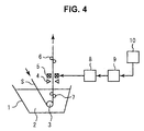
- Fig. 4 shows an example of apparatus for producing hot-dip metal coated steel sheet according to the present invention.
- the apparatus for producing hot-dip metal coated steel sheet has: a hot-dip metal coating tank 1 which holds the hot-dip metal coating bath 2 to which the steel sheet S is drawn in to adhere the molten metal to the steel sheet; the gas-wiping device 4 which adjusts the coating weight of molten metal adhered to the steel sheet S after drawn up from the coating bath 2; the electromagnets 5; and support rolls 6 outside the bath.
- the apparatus further has a current control device 8, a preset control computer 9; and a line control device 10, as the control devices for the electromagnets 5.
- the hot-dip metal coating bath tank 1 has the sink roll 3 as the direction-change device which changes the running direction of the steel sheet s in the coating bath 2. Furthermore, the tank 1 may have the support rolls 7 which support the steel sheet s in the coating bath 2 after changed the running direction thereof. Although the support rolls 7 have an effect of suppressing vibration and correcting warp of the steel sheet, they may induce dross defects on the steel sheet S by catching dross in the coating bath, in some cases. According to the present invention, however, since the electromagnets 5 fully conduct the suppression of vibration and the correction of warp, the support rolls 7 are not necessarily required, and rather they are preferably not applied from the point of prevention of surface defects on the steel sheet S.
- the gas-wiping device 4 and the electromagnets 5 are located between the surface of coating bath 2 and the support rolls 6 outside the bath.
- the electromagnets 5 are positioned above and/or below the gas-wiping device 4. Since, however, zinc is emitted to deposit at downstream side of the gas-wiping device 4, the electromagnets 5 are preferably located to above the gas-wiping device 4.
- the distance between the front end of the gas injection opening (wiping nozzle) of the gas-wiping device 4 and the steel sheet S is about 15 mm to prevent contact between the wiping nozzle and the steel sheet in case that the warp condition of steel sheet suddenly changes at the joint between the forerunning steel sheet and the succeeding one. Since, however, the present invention can correct the warp over the whole length of the steel sheet, the conventional distance 15 mm between the front end of the wiping nozzle and the steel sheet S can be decreased.
- the electromagnet 5 is positioned facing the steel sheet surface to generate magnetic force in the direction crossing the surface of the steel sheet.
- the electromagnet 5 has functions of suppressing the vibration of the steel sheet s and of correcting the warp generated on the steel sheet S caused by the deformation under bending and returning given by the sink roll 3 and the support rolls 7 in the coating bath.
- plurality of electromagnets 5 is arranged in the width direction of the steel sheet, for example, and the selected number thereof is used depending on the magnitude of the warp in the width direction.
- the apparatus using electromagnets in the related art requires a position sensor to determine the position of the steel sheet. Since, however, the present invention applies what is called the "preset control" , that kind of position sensor is not necessarily required. From the viewpoint of cost and of size of apparatus, the position sensor is preferably eliminated.
- the steel sheet s immersed in the coating bath 2 is changed the running direction by the sink roll 3, and is drawn up from the coating bath 2, and then the coating weight thereon is adjusted by the gas-wiping device 4. At that moment, the steel sheet s passed the sink roll 3 is supported by the support rolls 7 in the bath and by the support rolls 6 outside the bath, while the vibration of the steel sheet s is suppressed by the magnetic force generated from the electromagnets 5 positioned between these support rolls, and also the warp is corrected thereby.
- the current control of the electromagnet 5 is carried out by the steps described below.
- data of various kinds of operating conditions is transmitted from the line control device 10 to the preset control computer 9.
- the preset control computer 9 determines the current value for the preset control.
- the method for determining the current value may be the one using a preliminarily prepared table value or the one using computation with a model formula prepared in advance.
- an adequate current value current value to make the steel sheet flat at the stable neutral point
- determined current value is applied to the operating condition.
- the operating conditions may take into account of the thickness, width, kind, and tension of the steel sheet, the diameter, contact angle, and friction force of upstream roll, the feed rate to the roll, and the like.
- the model formula my be derived from a physical model which expresses the generation of warp, the attraction force of electromagnet, and the like, or may be derived by applying multiple regression analysis to the operating conditions.
- the current control device 8 generates a command to control the output of electromagnet 5.
- the current value applied to the electromagnet 5 may be changed to a current value preliminarily determined on the basis of information of the succeeding steel sheet.
- Fig. 6 shows an example of preset control flow diagram according to the present invention.
- the flow shown by solid line is the flow of preset control applied to the forerunning steel sheet under the treatment described above.
- the operating conditions for the succeeding steel sheet, transmitted from the line control device 10, are used to calculate the optimum current value by the preset control computer 9 using table value or model formula.
- the preset control computer 9 receives the signal from the line control device 10 notifying that the joint between the forerunning steel sheet and the succeeding steel sheet passes the point of the gas-wiping device 4 or the electromagnets 5, and generates the optimum current value for the electromagnets 5 to the current control device 8.
- the current value of electromagnet 5 is set to the optimum value.
- the application of preset control as the current control of the electromagnet 5 allows the warp correction over the whole length of the steel sheet including the joint between the forerunning steel sheet and the succeeding steel sheet and nearby sections thereof. Furthermore, since no support roll 7 in the bath is applied, the preset model can further be simplified. In addition, it is possible to prevent the generation of surface defects caused by the rolls in the bath and to decrease the maintenance cost for the rolls. Since, furthermore, the front end of the wiping nozzle of the gas-wiping device 4 and the steel sheet s can be brought to close with each other, the operation under low gas pressure is available to suppress the generation of splash defects.
- Fig. 7 shows another example of apparatus for producing hot-dip metal coated steel sheet according to the present invention.
- the apparatus for producing hot-dip metal coated steel sheet has the structure of the apparatus given in Fig. 4, and further has a steel sheet shape measuring device 11 located near the gas-wiping device 4, a coating weight measuring device 12 located downstream the support rolls 6 outside the bath, and a feedback control computer 13 as a control device for the electromagnets 5.
- a steel sheet shape measuring device 11 located near the gas-wiping device 4
- a coating weight measuring device 12 located downstream the support rolls 6 outside the bath
- a feedback control computer 13 as a control device for the electromagnets 5.
- the feedback control recognizes the warp of steel sheet on the basis of information determined by the shape measuring device 11 and/or the coating weight measuring device 12, thus changes the current value of electromagnet 5.
- the shape measuring device 11 and the coating weight measuring device 12 are installed to recognize the condition of vibration and warp of the steel sheet s, both of them are not necessarily applied.
- the shape measuring device 11 determines the magnitude of warp of the steel sheet S, and the device 11 is not necessarily requested to measure the whole width of the steel sheet S.
- the device 11 may be a position sensor that measures only the central section and the edges in the width direction of the steel sheet S.
- the shape measuring device 11 is preferably close to the gas-wiping device 4 as far as possible.
- the shape measuring device 11 is preferably positioned above the gas-wiping device 4 to avoid the influence of emitted zinc.
- the coating weight measuring device 12 determines the coating weight on the steel sheet S and determines the distribution of coating weight in the width direction of the steel sheet S. Based on the distribution of coating weight, the distance between the gas-wiping device 4 and the steel sheet S, or the warp of the steel sheet s, can be estimated.
- the shape of steel sheet S is determined by the shape measuring device 11, or the distribution of coating weight on the surface of steel sheet in the width direction is determined by the coating weight measuring device 12.
- the acquired information is transmitted to the feedback control computer 13 to derive the warp of the steel sheet S.
- the changing value of current which is set in the feedback control is determined.
- the changing value may, similar with the preset control, be determined based on the preliminarily prepared table value or may be determined by structuring a model formula.
- Thus calculated changing value for the current is transmitted to the current control device 8, and the command generated from the current control device 8 controls the output of electromagnet 5.
- Fig. 8 shows an example of feedback control flow diagram according to the present invention.
- the flow expressed by solid line is the preset control flow described in the First mode.
- the shape data determined by the shape measuring device 11 or the data of distribution of coating weight in the width direction of the steel sheet, determined by the coating weight measuring device 12, are transmitted to the feedback control computer 13. If the coating weight measuring device 12 is applied, the relation between the distribution of coating weight in the width direction and the shape of steel sheet is determined in advance, and the shape of the steel sheet is determined based on the relation. The warp of the steel sheet is calculated from the shape data. Using the various operating conditions generated from the line control device 10, the feedback control computer 13 calculates the changing value of the current of electromagnet 5 using the table value or the model formula. Then, the changing value for the current is sent to the current control device 8.
- the preset control described in the First mode actualizes almost flat steel sheet.
- error in the preset accuracy may occur from indeterminate causes such as error in model and wear of roll.
- further feedback control may be given to measure the actual warp of the steel sheet, and the output of electromagnet is corrected by the measured value to obtain more flat steel sheet. It is preferable to consider that kind of preset error and to conduct error-learning reflecting the error to the succeeding preset.
- Fig. 9 compares the shape controllability between the present invention and the related art.
- the First mode according to the present invention suppresses the warp to a specified range over the whole length of the steel sheet owing to the preset control.
- feedback control is given adding to the preset control so that the error generated in the preset control can be corrected, thus the steel sheet is controlled to flat shape almost whole length thereof.
- the First mode and the Second mode described the method of conducting the control of the current of electromagnet 5.
- the adjustment of the magnetic force of electromagnet 5 is, however, attained also by adjusting the distance between the electromagnet 5 and the steel sheet. Accordingly, instead of applying the control of current of the electromagnet 5, similar effect is attained by adjusting the distance between the electromagnet 5 and the steel sheet.
- the First mode and the Second mode can correct the warp over the whole length of the steel sheet, and the generation of surface defects caused by the roll immersed in the bath is prevented without using support roll in the bath, and further the generation of splash defects is prevented by decreasing the distance between the front end of the wiping nozzle of gas-wiping device and the steel sheet.
- the First mode and the Second mode are able to manufacture high quality hot-dip galvanized steel sheet.
- the hot-dip galvanized steel sheet coils were prepared using the apparatuses for producing hot-dip metal coated steel sheet according to the present invention, shown in Fig. 4 and Fig. 10, respectively, under the four kinds of conditions of electromagnet and sensor, given in Table 1.
- Example 1 Under the condition of Example 1 according to the present invention, the preset control of electromagnet was given by the producing apparatus of Fig. 4.
- the apparatus does not need special sensor and has a simple facility configuration so that the electromagnets were positioned above the wiping nozzle by 250 mm therefrom, or close to the wiping nozzle.
- the distance between the wiping nozzle and the steel sheet was as narrow as 7 mm.
- the support roll immersed in the bath both cases of use and not-use were studied.
- Example 2 used the shape measuring device
- Example 3 used the coating weight measuring device.
- the electromagnets since the shape measuring device was located near and above the wiping nozzle in Example 2, the electromagnets were positioned above the wiping nozzle by 500 mm therefrom. In Example 3, however, the electromagnets were positioned above the wiping nozzle by 250 mm therefrom. The distance between the wiping nozzle and the steel sheet was 7 mm, which is narrow. For the support roll immersed in the bath, both cases of use and not-use were studied, similar with Example 1.
- Comparative Example gave about ⁇ 10 g/m 2 of coating weight, which is non-uniform, while Examples 1 to 3 showed almost uniform coating weight at around ⁇ 3 g/m 2 .
- the superiority comes from that, Comparative Example which used the feedback control of electromagnet could not respond to the changes of warp at the front end of succeeding steel sheet at the joint between the forerunning steel sheet and the succeeding steel sheet, and that Examples 1 to 3 which applied the preset control of electromagnet could adequately correct the warp on and after the front end of succeeding steel sheet.
- Example 1 For the distribution of coating weight in the width direction at central portion of the steel sheet along the longitudinal direction, Example 1 gave the coating weight of about ⁇ 3 g/m 2 similar with that at the front end of the steel coil, and Examples 2 and 3 gave an improvement to about ⁇ 1 to 2 g/m 2 of the coating weight.
- the improvement comes from that Example 1 which applied only the preset control of electromagnet left some degree of warp in some cases caused by the error of feedback control, though the warp of steel sheet could almost be flattened, while Examples 2 and 3 which conducted the feedback control adding to the preset control of electromagnet could correct the shape, even when the preset control generated error, by correcting the error by the feedback control.
- Example 1 Example 2 Example 3 Comparative Example Electromagnet Use Use Use Use Use Method of electromagnet control Preset Preset + Feedback Preset + Feedback Feedback Sensor Not-use Shape measuring device Coating weight measuring device Shape measuring device Position of electromagnet (above the nozzle) 250mm 500mm 250mm 500mm Distance between nozzle and steel sheet 7mm 7mm 7mm 15mm Support roll immersed in bath Use/Not-use Use/Not-use Use/Not-use Use/Not-use Use
Landscapes
- Chemical & Material Sciences (AREA)
- Engineering & Computer Science (AREA)
- Chemical Kinetics & Catalysis (AREA)
- Materials Engineering (AREA)
- Mechanical Engineering (AREA)
- Metallurgy (AREA)
- Organic Chemistry (AREA)
- Computer Hardware Design (AREA)
- Coating With Molten Metal (AREA)
Applications Claiming Priority (3)
| Application Number | Priority Date | Filing Date | Title |
|---|---|---|---|
| JP2002187519 | 2002-06-27 | ||
| JP2002187519A JP2004027315A (ja) | 2002-06-27 | 2002-06-27 | 溶融金属めっき鋼板の製造方法および製造装置 |
| PCT/JP2003/007924 WO2004003249A1 (ja) | 2002-06-27 | 2003-06-23 | 溶融金属めっき鋼板の製造方法および製造装置 |
Publications (1)
| Publication Number | Publication Date |
|---|---|
| EP1516939A1 true EP1516939A1 (de) | 2005-03-23 |
Family
ID=29996789
Family Applications (1)
| Application Number | Title | Priority Date | Filing Date |
|---|---|---|---|
| EP03738502A Withdrawn EP1516939A1 (de) | 2002-06-27 | 2003-06-23 | Verfahren und vorrichtung zur herstellung eines mit schmelzflüssigem metall beschichteten stahlblechs |
Country Status (5)
| Country | Link |
|---|---|
| EP (1) | EP1516939A1 (de) |
| JP (1) | JP2004027315A (de) |
| KR (1) | KR100758240B1 (de) |
| CN (1) | CN1659301A (de) |
| WO (1) | WO2004003249A1 (de) |
Cited By (9)
| Publication number | Priority date | Publication date | Assignee | Title |
|---|---|---|---|---|
| WO2006021436A1 (de) * | 2004-08-24 | 2006-03-02 | Betriebsforschungsinstitut VDEh-Institut für angewandte Forschung GmbH | Verfahren zur führung eines bandes und verwendung für ein solches verfahren |
| WO2006021437A1 (de) * | 2004-08-24 | 2006-03-02 | Betriebsforschungsinstitut VDEh - Institut für angewandte Forschung GmbH | Verfahren zur bandbeschichtung |
| WO2006136700A1 (fr) * | 2005-06-24 | 2006-12-28 | Fives Celes | Dispositif et procede de guidage d'une bande metallique dans des equipements de traitement en continu. |
| EP1918410A3 (de) * | 2006-11-03 | 2009-02-25 | EMG Automation GmbH | Vorrichtung zum Stabilisieren des Laufs eines Metallbandes |
| EP1896625A4 (de) * | 2005-06-30 | 2010-07-14 | Abb Ab | Vorrichtung und verfahren zum kontrollieren der dicke |
| EP2848711A4 (de) * | 2012-05-10 | 2016-01-06 | Nippon Steel & Sumitomo Metal Corp | Stahlblechformkontrollverfahren und vorrichtung zur stahlblechformkontrolle |
| DE102016222224A1 (de) | 2016-02-23 | 2017-08-24 | Sms Group Gmbh | Verfahren zum Betreiben einer Beschichtungseinrichtung zum Beschichten eines Metallbandes sowie Beschichtungseinrichtung |
| IT202000016012A1 (it) * | 2020-07-02 | 2022-01-02 | Danieli Off Mecc | Apparato di correzione della planarità di un nastro metallico e relativo metodo di correzione |
| US20220049339A1 (en) * | 2016-08-26 | 2022-02-17 | Fontaine Engineering Und Maschinen Gmbh | Method and coating device for coating a metal strip |
Families Citing this family (8)
| Publication number | Priority date | Publication date | Assignee | Title |
|---|---|---|---|---|
| JP4525105B2 (ja) * | 2004-02-23 | 2010-08-18 | Jfeスチール株式会社 | 金属帯の制御装置および溶融めっき金属帯の製造方法 |
| JP5022770B2 (ja) * | 2007-05-11 | 2012-09-12 | 三菱日立製鉄機械株式会社 | 溶融金属めっき板の製造方法、溶融金属めっき設備及びその制御装置 |
| JP5223451B2 (ja) * | 2008-05-17 | 2013-06-26 | Jfeスチール株式会社 | 溶融めっき金属帯の製造方法 |
| JP2013239335A (ja) * | 2012-05-15 | 2013-11-28 | Sharp Corp | バックライトユニットおよび液晶表示装置 |
| KR101517782B1 (ko) | 2013-08-30 | 2015-05-06 | 주식회사 포스코 | 용융 아연 도금 공정용 강판 평탄도 교정 장치 |
| JPWO2020121646A1 (ja) * | 2018-12-11 | 2021-02-15 | Jfeスチール株式会社 | 溶融金属めっき鋼板の製造方法、溶融金属めっき鋼板の製造装置 |
| CN114934249A (zh) * | 2022-06-15 | 2022-08-23 | 武汉钢铁有限公司 | 控制热镀锌带钢c翘缺陷的方法、装置及电子设备 |
| CN116005092B (zh) * | 2022-12-14 | 2023-09-12 | 河北燕赵蓝天板业集团有限责任公司 | 一种减少热镀锌钢板表面锌渣的梯度式补热装置及方法 |
Family Cites Families (12)
| Publication number | Priority date | Publication date | Assignee | Title |
|---|---|---|---|---|
| KR950000007B1 (ko) * | 1991-06-25 | 1995-01-07 | 니홍고오깡가부시끼가이샤 | 용융도금의 강대상에 도포중량을 제어하기 위한 방법 |
| JP2601067B2 (ja) * | 1991-06-25 | 1997-04-16 | 日本鋼管株式会社 | 溶融めっき鋼板の目付方法 |
| JP2601068B2 (ja) * | 1991-06-25 | 1997-04-16 | 日本鋼管株式会社 | 溶融めっき鋼板の目付方法 |
| JP2556220B2 (ja) * | 1991-08-26 | 1996-11-20 | 日本鋼管株式会社 | 溶融めっき鋼板の目付方法 |
| JPH0525387A (ja) * | 1991-07-24 | 1993-02-02 | Hitachi Chem Co Ltd | 含フツ素ポリイミド前駆体組成物および含フツ素ポリイミドのパターン製造法 |
| JPH06287736A (ja) * | 1993-04-05 | 1994-10-11 | Mitsubishi Heavy Ind Ltd | 連続めっき装置 |
| KR950000007A (ko) * | 1993-06-14 | 1995-01-03 | 김종립 | 차(茶)버섯을 배양하는 방법 |
| JP3574204B2 (ja) * | 1995-01-24 | 2004-10-06 | 新日本製鐵株式会社 | 溶融めっき鋼板のめっき付着量制御装置及び方法 |
| JP3111857B2 (ja) * | 1995-07-06 | 2000-11-27 | 日本鋼管株式会社 | 溶融めっき鋼板の形状制御方法 |
| JP2002294426A (ja) * | 2001-03-29 | 2002-10-09 | Mitsubishi Heavy Ind Ltd | めっき付着量制御装置及び方法 |
| JP3530514B2 (ja) * | 2001-08-02 | 2004-05-24 | 三菱重工業株式会社 | 鋼板形状矯正装置及び方法 |
| JP2003105515A (ja) * | 2001-09-26 | 2003-04-09 | Mitsubishi Heavy Ind Ltd | 鋼板形状矯正装置及び方法 |
-
2002
- 2002-06-27 JP JP2002187519A patent/JP2004027315A/ja active Pending
-
2003
- 2003-06-23 KR KR1020047019072A patent/KR100758240B1/ko not_active Expired - Fee Related
- 2003-06-23 CN CN038135698A patent/CN1659301A/zh active Pending
- 2003-06-23 EP EP03738502A patent/EP1516939A1/de not_active Withdrawn
- 2003-06-23 WO PCT/JP2003/007924 patent/WO2004003249A1/ja not_active Ceased
Non-Patent Citations (1)
| Title |
|---|
| See references of WO2004003249A1 * |
Cited By (14)
| Publication number | Priority date | Publication date | Assignee | Title |
|---|---|---|---|---|
| WO2006021436A1 (de) * | 2004-08-24 | 2006-03-02 | Betriebsforschungsinstitut VDEh-Institut für angewandte Forschung GmbH | Verfahren zur führung eines bandes und verwendung für ein solches verfahren |
| WO2006021437A1 (de) * | 2004-08-24 | 2006-03-02 | Betriebsforschungsinstitut VDEh - Institut für angewandte Forschung GmbH | Verfahren zur bandbeschichtung |
| WO2006136700A1 (fr) * | 2005-06-24 | 2006-12-28 | Fives Celes | Dispositif et procede de guidage d'une bande metallique dans des equipements de traitement en continu. |
| FR2887707A1 (fr) * | 2005-06-24 | 2006-12-29 | Celes Sa | Dispositif et procede de guidage d'une bande metallique dans des equipements de traitement en continu |
| EP1896625A4 (de) * | 2005-06-30 | 2010-07-14 | Abb Ab | Vorrichtung und verfahren zum kontrollieren der dicke |
| EP1918410A3 (de) * | 2006-11-03 | 2009-02-25 | EMG Automation GmbH | Vorrichtung zum Stabilisieren des Laufs eines Metallbandes |
| EP2848711A4 (de) * | 2012-05-10 | 2016-01-06 | Nippon Steel & Sumitomo Metal Corp | Stahlblechformkontrollverfahren und vorrichtung zur stahlblechformkontrolle |
| US10343867B2 (en) | 2012-05-10 | 2019-07-09 | Nippon Steel Corporation | Steel sheet shape control method and steel sheet shape control apparatus |
| DE102016222224A1 (de) | 2016-02-23 | 2017-08-24 | Sms Group Gmbh | Verfahren zum Betreiben einer Beschichtungseinrichtung zum Beschichten eines Metallbandes sowie Beschichtungseinrichtung |
| WO2017144194A1 (de) | 2016-02-23 | 2017-08-31 | Sms Group Gmbh | Verfahren zum betreiben einer beschichtungseinrichtung zum beschichten eines metallbandes sowie beschichtungseinrichtung |
| US10982307B2 (en) | 2016-02-23 | 2021-04-20 | Fontaine Engineering Und Maschinen Gmbh | Method for operating a coating device for coating a metal strip, and coating device |
| US20220049339A1 (en) * | 2016-08-26 | 2022-02-17 | Fontaine Engineering Und Maschinen Gmbh | Method and coating device for coating a metal strip |
| IT202000016012A1 (it) * | 2020-07-02 | 2022-01-02 | Danieli Off Mecc | Apparato di correzione della planarità di un nastro metallico e relativo metodo di correzione |
| WO2022003646A1 (en) * | 2020-07-02 | 2022-01-06 | Danieli & C. Officine Meccaniche S.P.A. | Correction apparatus for correcting the planarity of a metal strip and related correction method |
Also Published As
| Publication number | Publication date |
|---|---|
| WO2004003249A1 (ja) | 2004-01-08 |
| CN1659301A (zh) | 2005-08-24 |
| KR20050014836A (ko) | 2005-02-07 |
| KR100758240B1 (ko) | 2007-09-12 |
| JP2004027315A (ja) | 2004-01-29 |
Similar Documents
| Publication | Publication Date | Title |
|---|---|---|
| EP1516939A1 (de) | Verfahren und vorrichtung zur herstellung eines mit schmelzflüssigem metall beschichteten stahlblechs | |
| US10343867B2 (en) | Steel sheet shape control method and steel sheet shape control apparatus | |
| CA2409159C (en) | Method for manufacturing hot-dip plated metal strip and apparatus for manufacturing the same | |
| US8062711B2 (en) | Device and a method for stabilizing a steel sheet | |
| KR101130483B1 (ko) | 스트립형 기판 상에 코팅을 연속 퇴적시키는 방법 및 설비 | |
| JP2012102389A (ja) | 溶融金属めっき設備 | |
| JPH08199323A (ja) | 溶融めっき鋼板のめっき付着量制御装置及び方法 | |
| JPH1060614A (ja) | 電磁力を利用しためっき付着量調整方法及び装置 | |
| JP5644141B2 (ja) | 金属帯の制振及び位置矯正装置、および該装置を用いた溶融めっき金属帯製造方法 | |
| JP3111857B2 (ja) | 溶融めっき鋼板の形状制御方法 | |
| JP4525105B2 (ja) | 金属帯の制御装置および溶融めっき金属帯の製造方法 | |
| JP2002275614A (ja) | 溶融めっき鋼板のめっき付着量制御方法 | |
| WO2019106785A1 (ja) | 金属板の板反り矯正装置及び金属板の連続めっき処理設備 | |
| JP5169089B2 (ja) | 連続溶融金属めっき方法 | |
| JPH08197139A (ja) | 鋼板形状制御装置 | |
| JP2002275613A (ja) | めっき付着量制御方法及び制御システム | |
| JP2002275610A (ja) | 金属帯形状制御装置 | |
| JP4775035B2 (ja) | 金属帯の溶融めっき方法及び溶融めっき設備 | |
| JP3535131B2 (ja) | 溶融めっき鋼帯の製造方法 | |
| JPH07126824A (ja) | 溶融金属めっき鋼板の製造方法 | |
| JP4505432B2 (ja) | 鋼板の形状矯正方法及び形状矯正装置 | |
| JPH1046309A (ja) | めっき付着量の制御方法及び装置 | |
| JP2000273610A (ja) | 連続溶融めっき時の鋼帯幅反り制御方法及び装置 | |
| JP2025177251A (ja) | 溶融金属めっき鋼帯の製造方法及びガスワイピング装置 | |
| JP2015160959A (ja) | 金属帯の非接触制御装置および溶融めっき金属帯の製造方法 |
Legal Events
| Date | Code | Title | Description |
|---|---|---|---|
| PUAI | Public reference made under article 153(3) epc to a published international application that has entered the european phase |
Free format text: ORIGINAL CODE: 0009012 |
|
| 17P | Request for examination filed |
Effective date: 20041222 |
|
| AK | Designated contracting states |
Kind code of ref document: A1 Designated state(s): AT BE BG CH CY CZ DE DK EE ES FI FR GB GR HU IE IT LI LU MC NL PT RO SE SI SK TR |
|
| AX | Request for extension of the european patent |
Extension state: AL LT LV MK |
|
| DAX | Request for extension of the european patent (deleted) | ||
| RBV | Designated contracting states (corrected) |
Designated state(s): DE |
|
| STAA | Information on the status of an ep patent application or granted ep patent |
Free format text: STATUS: THE APPLICATION IS DEEMED TO BE WITHDRAWN |
|
| 18D | Application deemed to be withdrawn |
Effective date: 20070103 |