EP1544909A1 - Sondenverfahren, sondierer und elektrodenverringerungs/-plasmaätzprozessmechanismus - Google Patents
Sondenverfahren, sondierer und elektrodenverringerungs/-plasmaätzprozessmechanismus Download PDFInfo
- Publication number
- EP1544909A1 EP1544909A1 EP03794165A EP03794165A EP1544909A1 EP 1544909 A1 EP1544909 A1 EP 1544909A1 EP 03794165 A EP03794165 A EP 03794165A EP 03794165 A EP03794165 A EP 03794165A EP 1544909 A1 EP1544909 A1 EP 1544909A1
- Authority
- EP
- European Patent Office
- Prior art keywords
- gas
- reducing
- tested
- electrode
- prober
- Prior art date
- Legal status (The legal status is an assumption and is not a legal conclusion. Google has not performed a legal analysis and makes no representation as to the accuracy of the status listed.)
- Withdrawn
Links
Images


Classifications
-
- G—PHYSICS
- G01—MEASURING; TESTING
- G01R—MEASURING ELECTRIC VARIABLES; MEASURING MAGNETIC VARIABLES
- G01R31/00—Arrangements for testing electric properties; Arrangements for locating electric faults; Arrangements for electrical testing characterised by what is being tested not provided for elsewhere
- G01R31/28—Testing of electronic circuits, e.g. by signal tracer
- G01R31/2851—Testing of integrated circuits [IC]
- G01R31/2886—Features relating to contacting the IC under test, e.g. probe heads; chucks
-
- H—ELECTRICITY
- H10—SEMICONDUCTOR DEVICES; ELECTRIC SOLID-STATE DEVICES NOT OTHERWISE PROVIDED FOR
- H10P—GENERIC PROCESSES OR APPARATUS FOR THE MANUFACTURE OR TREATMENT OF DEVICES COVERED BY CLASS H10
- H10P74/00—Testing or measuring during manufacture or treatment of wafers, substrates or devices
Definitions
- the present invention relates to a probe method, a prober, and an electrode reducing/plasma-etching process mechanism. More specifically, the present invention relates to a probe method, a prober, and an electrode reducing/plasma-etching process mechanism which can improve the electrical contact state of the electrode of an object to be tested and a probe pin.
- a process of manufacturing an electrical product and electrical component includes various steps such as a film formation step of forming various types of metal layers such as an interconnection layer on a target object (e.g., a wafer), a step of testing the object to be tested which is formed on the wafer, and a step of testing the packaged object to be tested.
- a probe pin is brought into contact with an electrode of the object to be tested.
- a measurement signal is applied to the object to be tested from a tester through the probe pin.
- the electrode cannot be electrically connected to the probe pin by merely bringing the probe pin into contact with the electrode. In this case, a test signal cannot be applied to the electrode from the tester.
- the probe pin scrubs the electrode surface to break the oxide film on the electrode surface, so that the probe pin and electrode are brought into electrical contact with each other.
- the thicknesses of the deposition layers of the semiconductor products decrease acceleratingly. Electrodes also become thin. If the probe pin is brought into contact with the electrode with a needle pressure of a degree that barely breaks the oxide film, as in the conventional probe method, the needle pressure of the probe pin may undesirably change the electrical characteristics of the semiconductor product. When the lower layer of the electrode is made of a soft material such as a low-k material that has a low dielectric constant, the probe pin cannot be brought into contact with the electrode with such needle pressure.
- Jpn. Pat. Appln. KOKAI Publication No. 2000-311868 (claim 14 and paragraph [0041]) describes, in a process of forming a via hole for connecting different interconnection layers in a multilayered interconnection, a process of cleaning the via hole before forming an upper metal interconnection.
- a native oxide film and the like formed in the via hole in the surface of a silicon substrate are removed by using negative hydrogen ions generated by supplying electrons to hydrogen radicals.
- a gas containing hydrogen atoms is subjected to microwave discharge irradiation in a vacuum container, thus generating a hydrogen plasma.
- An electron supply device supplies thermoelectrons to the hydrogen radicals to generate negative hydrogen ions.
- the negative hydrogen ions are used for cleaning.
- a probe pin is brought into electrical contact with an electrode on the wafer surface. While the probe pin and electrode are in electrical contact with each other, testing of the object to be tested is performed. If an oxide film is present on the electrode surface, as the oxide film is an insulator, it interferes with electrical contact of the probe pin and electrode. For this reason, the oxide film on the electrode surface must be removed prior to testing.
- a reducing method described in Jpn. Pat. Appln. KOKAI Publication No. 2000-311868 can be used. With this reducing method, however, the wafer is exposed to harsh conditions. Accordingly, elements formed on the wafer may be damaged, decreasing the yield.
- U.S.P. No. 6,191,416 B1 (claims and the fourth column, 4 to 16 lines) describes an apparatus which generates free atoms or radical particles.
- This apparatus has a tube for supplying a gas, e.g., hydrogen gas or halogen gas, and a wire extending along the tube and connected to a power supply. A current is supplied to the wire to heat it. The radiation heat of the wire heats the gas flowing in the tube to 1,500°K to 2,500°K, to thermally decompose the gas, thus forming an atomic material or radicals. The atomic material or radicals of the gas serve to reduce other materials.
- This apparatus is compact and inexpensive when compared to that of Jpn. Pat. Appln. KOKAI Publication No. 2000-311868. However, the tube must be heated to a high temperature.
- the present invention is based on the above problems and solves at least one of them. According to one aspect of the present invention, there can be provided a probe method, a prober, and an electrode reducing/plasma-etching process mechanism which can bring probe pins into electrical contact with electrodes with as low a needle pressure as possible.
- an oxide and the like on the metal layer surface or electrode layer surface of a target object can be reduced under an atmospheric pressure at a comparatively low heating temperature.
- a target object reducing method with which damage to the target object can be decreased.
- a probe method of bringing a probe pin into electrical contact with, of an object to be tested having electrodes, at least one electrode to test electrical characteristics of the object to be tested comprises: (a) performing at least one of a reducing process and plasma-etching process for the electrode of the object to be tested; (b) bringing the testing electrode and the probe pin into contact with each other in a non-oxidizing atmosphere; and (c) testing the electrical characteristics of the object to be tested.
- This probe method preferably comprises any one of the following arrangements a) to j), or some arbitrary ones of the arrangements in combination.
- a reducing/plasma-etching process mechanism to perform at least one of a reducing process and plasma-etching process for an electrode of the object to be tested.
- the reducing/ plasma-etching process mechanism includes:
- the gas channel includes an inner wall surface, and a surface of the inner wall surface includes a catalyst metal.
- oxide films formed on the electrode surfaces of a wafer are reduced or plasma-etched by using, e.g., hydrogen gas or a reducing gas (forming gas as a gas mixture of hydrogen gas and nitrogen gas) containing hydrogen gas, to remove the oxide films partly or entirely (this will be described as "to remove the oxide films” hereinafter).
- hydrogen gas or a reducing gas forming gas as a gas mixture of hydrogen gas and nitrogen gas
- probe pins 14A When the oxide films on the electrodes are removed, probe pins 14A can be brought into electrical contact with the electrodes with a low needle pressure. Consequently, the electrodes will not be damaged by the probe pins 14A, and the service life of the probe pins 14A can be prolonged.
- a prober 10 of this embodiment can have a loader chamber (56 in FIG. 4) which transports a target object W (e.g., a wafer), a prober chamber 11 where the electrical characteristics of objects W' to be tested (to be referred to as integrated circuits hereinafter) formed on the wafer W are tested, and a controller 51 which controls various types of devices arranged in the two chambers.
- a target object W e.g., a wafer
- a prober chamber 11 where the electrical characteristics of objects W' to be tested (to be referred to as integrated circuits hereinafter) formed on the wafer W are tested
- a controller 51 which controls various types of devices arranged in the two chambers.
- the loader chamber 56 can include a stage portion where a cassette which stores, e.g., 25 wafers W, is to be placed, a wafer transporting mechanism 16A which transports the wafers W one by one from the cassette C, and a subchuck which aligns the wafers in a predetermined direction while the wafers W are being transported with the wafer transporting mechanism 16A.
- the prober chamber 11 can include a stage 13, a probe card 14 arranged above the stage 13, an alignment mechanism (not shown) which aligns probe pins 14A of the probe card 14 and electrodes P of the objects W' to be tested on the wafer W, and a process means (to be referred to as a "reducing/plasma-etching process mechanism" hereinafter) 15 which performs at least one of a reducing process and plasma-etching process for the electrodes P of the objects W' to be tested on the wafer W.
- a process means to be referred to as a "reducing/plasma-etching process mechanism” hereinafter
- the stage 13 can be moved in three-axis directions by a three-axis (X-axis, Y-axis, and Z-axis) moving mechanism 12 and can be rotated clockwise and counterclockwise in a ⁇ direction by a rotary mechanism.
- the stage 13 can also include a temperature adjusting mechanism 35J which adjusts the temperature of the objects W' to be tested which are placed on the stage 13.
- the probe pins 14A of the probe card 14 come into contact with the electrodes P of the integrated circuits formed on the wafer W, to connect the tester T and electrodes P to each other.
- the electrodes P can be made of a conductive metal, e.g., copper, a copper alloy, or aluminum.
- the reducing/plasma-etching process mechanism 15 removes the oxide films formed on the electrode surfaces of the objects (W') to be tested on the stage 13.
- the probe card 14 can be fixed to a head plate 16 on the upper portion of the prober chamber 11.
- a test head TH having a tester T is arranged on the head plate 16 such that the test head TH can be electrically connected to the probe card 14.
- the moving mechanism 12 can have a Y table 12A which moves in a Y direction (a direction perpendicular to the sheet surface in FIG. 1A) on the floor surface in the prober chamber 11, an X table 12B which moves in an X direction on the Y table 12A, and a Z-axis mechanism 12C which is arranged on the X table 12B.
- the moving mechanism 12 can be a mechanism that may use the principle of a linear motor.
- the moving mechanism 12 moves the stage 13 in the X, Y, and Z directions.
- the stage 13 can incorporate a temperature adjusting mechanism 35J which adjusts the temperature of the objects (W') to be tested which are placed on the stage 13 in the range of, e.g., -55 to 400°C.
- the stage 13 can be rotated clockwise and counterclockwise by a ⁇ -driving mechanism (not shown).
- the reducing/plasma-etching process mechanism (to be referred to as a reducing process mechanism hereinafter) 15 performs at least one of a reducing process and plasma-etching process for the oxide films on the electrode surfaces of the objects (W') to be tested which are placed and heated on the stage 13 under atmospheric pressure or reduced pressure. As shown in, e.g., FIG.
- the reducing process means 15 can have a gas supply container 15A arranged on the head plate 16 and made of a heat-resistant material such as, e.g., quartz or a ceramic material, a heater 15B arranged in the gas supply container 15A, a gas supply pipe 15C connected to the inlet of the gas supply container 15A, a gas supply source 15D which is connected to the gas supply pipe 15C and supplies a forming gas, and a mass flow controller 15H which controls the flow rate of the forming gas from the gas supply source 15D.
- the reducing process means 15 can heat the forming gas with the heater 15B in the gas supply container 15A.
- the heated forming gas reduces or plasma-etches the oxide films on the electrodes P of the objects W' to be tested which are heated on the stage 13.
- the gas supply container 15A can include a heat-insulating mechanism.
- the heat-insulating mechanism prevents temperature decrease in the gas supply container 15A.
- a gas discharge port 35K of the gas supply container 15A can be arranged such that it extends through the head plate 16 at a position adjacent to the probe card 14 and opposes the upper surface of the stage 13.
- the prober chamber 11 has an exhaust port 11A.
- the exhaust port 11A can be connected to an exhaust device 52 through an exhaust pipe 15E.
- a flat vessel 15F which has an open upper end and surrounds the stage 13 can be fixed to the upper portion of the moving mechanism 12.
- the vessel 15F can be formed to have a diameter larger than that of the stage 13.
- the vessel 15F can be filled with the forming gas supplied from the gas supply container 15A.
- a reducing atmosphere can be set in the interior of the vessel 15F with the forming gas.
- the gas discharge port 35K of the gas supply container 15A can be set at any position as far as it falls within the moving range of the stage
- the forming gas can be a gas mixture consisting of hydrogen gas and carrier gas (nitrogen gas).
- the forming gas in the prober chamber 11 can be adjusted by the mass flow controller 15H such that the content of the hydrogen gas falls within an non-explosive range (e.g., 5% by volume or less and more particularly approximately 3%).
- a noble gas such as argon or helium can be used.
- the inner surface of the prober chamber 11 can have a shield member 15G.
- the shield member 15G can hold the interior of the prober chamber 11 in an air-tight state to maintain the interior of the prober chamber in a predetermined reduced-pressure state.
- Oxygen concentration meters 17 can be arranged inside and outside the prober chamber 11. The oxygen concentration meters 17 measure the oxygen concentrations inside and outside the prober chamber 11. When an oxygen concentration meter 17 detects an oxygen concentration of a critical level, a warning unit 53 such as an alarm can produce a warning.
- the prober 10 can include a means 54 for supplying dry air.
- the dry air supply source 54 supplies dry air onto the stage in the prober chamber 11, so that the electrical characteristics of the objects W' to be tested can be tested in the dry atmosphere. With the dry atmosphere, those electrode surfaces of the objects W' to be tested from which the oxide films have been removed by the process mechanism 15 are prevented from being oxidized again by water in the air.
- the gas supply pipe 15C of the reducing process mechanism 15 can be utilized.
- the interior of the vessel 15F is filled with the forming gas, so that a reducing atmosphere is formed in the vessel 15F.
- the forming gas reduces the oxide films of the electrodes P of the objects W' to be tested which are already heated to a temperature of, e.g., 200°C or more by the temperature adjusting mechanism (35J) of the stage 13, to remove the oxide films on the electrode surfaces partly or entirely.
- the forming gas after the reducing process flows from the vessel 15F into the prober chamber 11, and is exhausted from the prober chamber 11 to the outside through the exhaust pipe 15E. During this operation, if air is not sufficiently exhausted from the prober chamber 11 and the oxygen concentration is higher than a predetermined preset value, the warning unit 53 produces a warning.
- the moving mechanism 12 drives to bring the probe pins 14A of the probe card 14 and the electrodes P of the objects W' to be tested into contact with each other.
- the probe pins 14A and the electrodes P need only be brought into contact with each other with a needle pressure lower than in the conventional case, so that they are brought into electrical contact with each other.
- the tester T can test the electrical characteristics of the objects W' to be tested.
- this embodiment includes reducing the oxide films on the electrodes P under the atmospheric pressure or reduced pressure by using the reducing gas (e.g., forming gas), and bringing the electrodes P and the probe pins 14A into electrical contact with each other in the dry atmosphere.
- the probe pins 14A and electrodes P need only be brought into contact with each other with a very low needle pressure (e.g., 0.2 mN or less), so that they are brought into electrical contact with each other.
- a very low needle pressure e.g., 0.2 mN or less
- Thin deposition layers such as the electrodes P or their underlying layers can be avoided from being damaged by the low needle pressure of the probe pins 14A.
- the hydrogen gas in the forming gas is activated by the heater 15B.
- the reducing process or plasma-etching process using activated hydrogen can remove the oxide films on the electrodes P within a short time.
- the reducing reaction/plasma-etching process can be promoted.
- the reducing process means 15 having the heater 15B is used.
- the heater 15B may be omitted, and only the gas supply source 15D may be provided.
- a reducing gas (forming gas) is supplied into the prober chamber 11 from the gas supply source 15D, to reduce the objects W' to be tested which are heated to a predetermined temperature (e.g., 200°C or more) on the stage 13.
- FIG. 2A shows another embodiment of the reducing process mechanism.
- a prober according to this embodiment is different from that of the above embodiment only in the reducing process mechanism.
- a reducing process mechanism 25 used in this embodiment has a palladium pipe (with a diameter of, e.g., 3 to 100 mm) 25A which is formed of a platinum group element (e.g., palladium) or its alloy into a pipe.
- the palladium pipe 25A is a gas channel.
- the reducing process mechanism 25 can have a pipe-like heater 25B surrounding the palladium pipe 25A, a heat-insulation pipe 25C for accommodating the heater 25B, and a storing pipe 25D which has a double-wall structure and accommodates the heat-insulation pipe 25C.
- the reducing process mechanism 25 can be attached to a head plate 16.
- a gas supply source 15D is connected to the upper end of the palladium pipe 25A through a gas supply pipe 25E.
- the gas supply source 15D supplies a gas (e.g., a forming gas) containing hydrogen gas to the palladium pipe 25A while controlling the flow rate of the gas with a mass flow controller 15H.
- a gas e.g., a forming gas
- Each of the heat-insulation pipe 25C and storing pipe 25D has a bottom surface with an outlet formed at its center.
- the bottom surface of the storing pipe 25D also has a double structure, and an inert gas such as nitrogen gas is supplied to a space between the two walls.
- the inert gas supplied from the outlet of the storing pipe 25D into a prober chamber purges air in the prober chamber.
- the palladium pipe 25A has a function of activating the hydrogen gas.
- the palladium pipe 25A may be of a mesh type or sponge type.
- a granular palladium catalyst or palladium coil may be arranged in a pipe made of a corrosion-resistant material.
- the operation of the reducing process mechanism 25 will be described.
- nitrogen gas is supplied from the storing pipe 25D into the prober chamber.
- the nitrogen gas purges air in the prober chamber.
- the heater 25B heats the palladium pipe 25A to the activation temperature (600°C or less) of hydrogen gas or a temperature for plasmatizing hydrogen.
- a forming gas is supplied from the gas supply source 15D to the palladium pipe 25A.
- Hydrogen gas in the forming gas is activated as it comes into contact with the palladium pipe 25A.
- the forming gas is supplied toward a wafer W in the prober chamber.
- the activated hydrogen gas reduces or plasma-etches the oxide films of electrodes P on the heated wafer W.
- the reducing process mechanism 25 can be preferably used when reducing or plasma-etching a metal material made of, e.g., copper or a copper alloy.
- FIG. 3A shows a reducing process mechanism 15 used in a prober according to still another embodiment of the present invention.
- the prober according to this embodiment can be formed in the same manner as in the above embodiments except for the reducing process mechanism 15.
- a reducing process mechanism 15 which is used in this embodiment and performs at least one of a reducing process and plasma-etching process is formed in a loader chamber 56, as shown in FIG. 3A.
- the reducing process mechanism 15 reduces the oxide films of electrodes P of the objects W' to be tested formed on the wafer W in the loader chamber 56.
- the reducing process mechanism 15 can include a processing vessel 35A, a temperature adjusting mechanism 35J which heats and cools the wafer W in the processing vessel 35A, a stage 13, a plurality of elevating pins 35C to receive the wafer W on the stage 13, a gas supply container 15A which is arranged above the processing vessel 35A and has a heater 15B, a gas supply pipe 15C connected to the gas supply container 15A, a gas supply source 15D, and a gas exhaust pipe 15E connected to the gas supply container 15A.
- a forming gas introduced from the gas supply source 15D through the gas supply pipe 15C is heated in the gas supply container 15A.
- the heated forming gas is introduced into the processing vessel 35A to reduce the oxide films of the electrodes P of the objects W' to be tested.
- a wafer transporting mechanism 16A is arranged in the loader chamber 56.
- the wafer transporting mechanism 16A transports the wafer W between a cassette C and the processing vessel 35A.
- dry air is supplied into the loader chamber 16, in the same manner as in the prober chamber, to adjust interior of the loader chamber 56 to a dry atmosphere.
- Reference symbol G denotes an opening/closing door to open/close the processing vessel 35A.
- the wafer transporting mechanism 16A extracts a wafer W from the cassette C, transports the wafer W into the processing vessel 35A through the opening/closing door G which is open, and places the wafer W from the stage 13 onto the elevating pins 35C that have moved upward.
- the elevating pins 35C move downward to place the wafer W on the stage 13.
- the heater 15B of the stage 13 heats the wafer W to a predetermined temperature.
- the forming gas is supplied from the gas supply source 15D into the gas supply container 15A.
- the forming gas is heated in the gas supply container 15A by the temperature adjusting mechanism 35J (e.g., to substantially the same temperature as that of the wafer W).
- the heated forming gas flows into the processing vessel 35A to reduce or plasma-etch the electrodes P of the objects W' to be tested on the wafer W.
- the wafer transporting mechanism 16A extracts the wafer W from the processing vessel 35A and transports it into the prober chamber 11. The electrical characteristics of the objects W' to be tested formed on the transported wafer W are tested in the prober chamber 11.
- FIG. 3B is different from the apparatus shown in FIG. 3A in that it does not include a heater 15B.
- a reducing process mechanism 15 shown in FIG. 3B supplies a reducing gas (e.g., a forming gas) from a gas supply source 15D to a processing vessel 35A.
- the reducing gas partly or entirely reduces the oxide films of electrodes P of heated objects W' to be tested which are on a stage 13 arranged in the processing vessel 35A.
- FIG. 4 shows a reducing process mechanism 15 used in a prober according to still another embodiment of the present invention.
- the prober according to this embodiment can be formed in the same manner as in the above embodiments except for the reducing process mechanism 15.
- the reducing process mechanism 15 used in this embodiment can include a loader chamber 56, a processing vessel 35 connected to the loader chamber 56 through a door G such that the processing vessel 35 can communicate with and be isolated from the loader chamber 56, a stage 13 arranged in the processing vessel 35 and serving as a lower electrode as well, an upper electrode 45C arranged above the stage 13 to be parallel to it and having a large number of gas supply holes, a gas supply source 15D for supplying a forming gas into the processing vessel 35, and an exhaust device 52 for exhausting the gas in the processing vessel 35.
- a dry atmosphere can be set in the loader chamber 56.
- the stage 13 can include a lower electrode 45F connected to an 11.56-MHz high-frequency power supply 45E, a heating portion 45G having a heater, a cooling portion 45H arranged under the heating portion 45G and having a refrigerant channel, and elevating pins (35C in FIG. 3A) for vertically moving a wafer W on the stage surface.
- a forming gas plasma is generated between the lower electrode 45F and upper electrode 45C.
- the heating portion 45G and cooling portion 45H adjust the temperature of the wafer W on the stage 13. As shown in, e.g., FIG.
- the gas supply source 15D can include a hydrogen gas supply source 45I for supplying hydrogen gas, a nitrogen gas supply source 45J for supplying nitrogen gas, and a mass flow controller 15E for adjusting the flow rates of the hydrogen gas and nitrogen gas.
- the mass flow controller 15E adjusts the hydrogen gas to a predetermined concentration and supplies it into the processing vessel 35.
- the processed gas from the processing vessel 35 is exhausted through the gas exhaust pipe 15E.
- a wafer W is extracted from a cassette.
- a wafer transporting mechanism transports the wafer W from the loader chamber 56 onto the stage 13 in the processing vessel 35.
- the gate valve G is closed to isolate the interior of the processing vessel 35 from external air.
- an exhaust device 52 exhausts air in the processing vessel 35.
- Air in the processing vessel 35 is purged with nitrogen gas.
- a forming gas consisting of hydrogen gas and nitrogen gas is supplied from the gas supply source 15D into the processing vessel 35 at a predetermined flow rate to purge air.
- the interior of the processing vessel 35 is maintained at a pressure that enables plasmatization.
- High-frequency power is applied to the lower electrode 45F, and a forming gas is generated between the lower electrode 45F and upper electrode 45C.
- the plasma etches the oxide films of copper electrodes P of the objects W' to be tested on the wafer W.
- the gate valve G is opened, and simultaneously the wafer transporting mechanism enters the processing vessel 35.
- the wafer transporting mechanism unloads the wafer W from the processing vessel 35 into the loader chamber 56.
- the gate valve G is closed.
- the wafer W is transported to the prober chamber through the loader chamber 56 which is adjusted to a dry atmosphere. After that, the electrical characteristics of the objects W' to be tested on the wafer W are tested in the prober chamber in the same manner as in the embodiments described above.
- the reducing performance of the forming gas was observed.
- the oxygen concentration distribution in the thin copper film was observed.
- the reference wafer was placed on a stage.
- the reference wafer was heated on the stage which was set at a temperature of 150°C.
- FIG. 5 shows the results of this observation. According to the results shown in FIG. 5, when the forming gas was supplied, the oxygen concentration became zero at% before the depth from the surface of the thin copper film reached 10 nm. This indicates that the oxide film is greatly thinner than in the reference wafer and is accordingly reliably reduced by the forming gas. In contrast to this, in a non-oxidizing atmosphere obtained by supplying the nitrogen gas, the oxygen concentration was higher than in the reference wafer.
- XPS X-ray photoelectron spectroscope
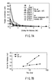
- the influence of the temperature of the stage when reducing the oxide film of a reference wafer by using a forming gas was observed. More specifically, as shown in FIG. 6, the temperature of the stage was changed between 250°C, 300°C, 325°C, and 350°C, and the oxygen concentration distribution in the thin copper film at each temperature was observed with the XPS. FIG. 6 shows the results of this observation. According to the results shown in FIG. 6, the higher the temperature of the stage, the more the reduction was promoted.
- FIG. 7A shows the results of this observation. Oxidation rates in dry air and in atmosphere were obtained.
- FIG. 7B shows the obtained results. Marks ⁇ in FIG. 7A indicate the oxygen concentration distribution in the thin copper film immediately after the copper wafer was fabricated. According to the results shown in FIGS.
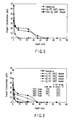
- the relationship between the needle pressure of the probe pins and the contact resistance of the oxide film of the copper wafer in a dry atmosphere was observed.
- FIGS. 8A to 8C show the relationship between the overdrive amount (needle pressure) and contact resistance.
- the needle pressure of the probe pins and the contact resistance were measured in dry air (dew point : -70°C) in the same manner.
- the results of the measurement are shown in FIGS. 9A to 9C.
- the needle pressure was 0 mN, 15 mN, and 50 mN, respectively.
- the resistance value was 5 ⁇ or less
- variations in the Z direction were 10 ⁇ m or less.
- the resistance value was stably 1 ⁇ or less in the entire surface of the copper wafer. In the atmosphere, the closer to the middle of the measurement time, the much higher the contact resistance value.
- the probe card a 14-pin probe card which generated a load of 0.2 mN when it was overdriven for 10 ⁇ m was used.
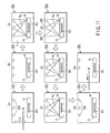
- FIG. 11 shows only the processing vessel 35A of FIG. 3B from the viewpoint of showing the process in the processing vessel 35A shown in FIG. 3B.
- a transporting mechanism transports a wafer W from the loader chamber 56 onto the elevating pins 35C of the stage 13 in the processing vessel 35A through the opening/closing door G.
- the elevating pins of the stage 13 move downward to place the wafer W on the stage 13.
- the stage can fix the wafer W with a vacuum chucking mechanism.
- the opening/closing door G is closed (see FIG. 11(b)).
- an inert gas e.g., nitrogen gas at a flow rate of 1 to 2 L/min
- an inert gas e.g., nitrogen gas at a flow rate of 1 to 2 L/min
- a reducing gas e.g., a forming gas with normal temperature at a flow rate of 1 to 2 L/min
- a reducing gas is supplied from the gas supply pipe 15C toward the wafer W on the stage 13 in the processing vessel 35A.
- a pipe 15C (with a diameter of, e.g., 3 to 100 mm) made of a platinum group metal (e.g., palladium) or a pipe 15C containing a palladium foil can be used, as shown in, e.g., FIG. 2B.
- a platinum group metal e.g., palladium
- a pipe 15C containing a palladium foil can be used, as shown in, e.g., FIG. 2B.
- the temperature adjusting mechanism 35J heats the stage 13, to quickly heat the wafer W on the stage 13 to, e.g., 150 to 270°C within a short time (e.g., 5 minutes).
- the forming gas reduces the electrodes P on the wafer W which are made of copper, a copper alloy, or the like for a short time (e.g., 5 to 20 minutes).
- the temperature adjusting mechanism 35J quickly cools the wafer W to a normal temperature within a short time (e.g., 5 minutes).
- a short time e.g., 5 minutes
- the stage 13 may be heated, the opening/closing door G may be closed, air in the processing vessel 35A may be purged with the forming gas, and after that the wafer W may be fixed to the stage 13 by chucking and reduced by heating.
- a cooling device 35M' shown in FIGS. 12A and 12B may be provided.
- the cooling device 35M' has a pair of cooling plates 22C that can be moved for enlargement or reduction. A case wherein this cooling device is used will be described.
- the wafer W is heated on the stage 13 in the processing vessel 35A, and is reduced.
- the elevating pins 35C lift the wafer W from the stage 13. In this state, the cooling plates 22C enter between the wafer W and stage 13 to sandwich the elevating pins 35C.
- the elevating pins 35C place the wafer W on the cooling plates 22C, or place it to be slightly separate from the cooling plates 22C.
- the wafer W is cooled by the cooling plates 22C. After cooling, the pair of cooling plates 22C retreat from the stage 13.
- the transporting mechanism 16A transports the wafer W supported by the elevating pins 35C to the prober chamber 11.
- the cooling plates 22C may not be used, and while the forming gas is supplied into the processing vessel 35A and the elevating pins 35C lift the wafer W from the stage 13, the wafer W may be cooled. Also, the forming gas may be supplied after the wafer W is lifted.
- Example 6 the reducing performance of room-temperature hydrogen gas and that of heated (activated) hydrogen gas were observed.
- a nitrogen atmosphere is set in the processing vessel 35A, an oxide film on a copper wafer is reduced in a forming gas atmosphere.
- the concentration distribution of oxygen atoms (to be merely referred to as "oxygen concentration distribution” hereinafter) in a reduced thin copper film layer was observed.
- the copper wafer is placed on the stage 13 which is set at a temperature of 350°C, and is heated to 270°C.
- a flow rate 1 L/min to 2 L/min
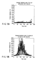
- the oxygen concentration becomes zero at% before the depth from the surface of the copper thin film layer reaches 20 nm, as indicated by the marks ⁇ in FIG. 13.
- an oxygen concentration of 7 at% to 8 at% was exhibited at a depth of 20 nm from the surface of the thin copper film layer, as indicated by the marks ⁇ in FIG. 13.
- the reducing performance with hydrogen is lower than in a case wherein the room-temperature forming gas is used. Accordingly, the forming gas at room temperature, i.e., room-temperature hydrogen gas, has a higher reducing ability than that of the heated hydrogen gas.
- the temperature in the thin copper film layer of the copper wafer is higher than the temperature of the surface of the thin copper film layer. It is estimated that diffusion of oxygen atoms in the thin copper film layer is delayed, so that reducing reaction by hydrogen is delayed. In other words, it is estimated that diffusion of oxygen atoms in the thin copper film layer controls the speed of the reducing reaction.
- Example 7 a copper wafer was placed in a nitrogen gas atmosphere, and the oxygen concentration distribution in the oxide film layer of the copper wafer was observed in a case wherein room-temperature hydrogen gas was supplied to the copper wafer and a case wherein such hydrogen gas was not supplied to it.
- the copper wafer was placed on the stage 13 heated to 350°C.
- a room-temperature forming gas was supplied to the copper wafer heated to 270°C at a flow rate of 1 to 2 L/min, to reduce the copper wafer for 20 min.
- the oxygen concentration distribution in the thin copper film layer was observed with the X-ray photoelectron spectroscope (XPS). As a result, an oxygen concentration distribution indicated by marks ⁇ in FIG. 14 was obtained.
- XPS X-ray photoelectron spectroscope
- Example 14 According to the results shown in FIG. 14, the same results as those of Example 6 are obtained, that is, when the room-temperature forming gas was supplied under the same conditions as those in Example 6, reduction in the thin copper film layer was promoted, as indicated by the marks ⁇ in FIG. 14.
- the copper wafer is heat-treated in a nitrogen gas atmosphere, oxidation reaction by oxygen contained as an impurity in the nitrogen gas progresses, as indicated by the marks ⁇ in FIG. 14, and the oxygen concentration becomes higher than that in an unprocessed copper wafer indicated by the marks ⁇ in FIG. 14.
- Example 8 the influence of the temperature of the copper wafer on reducing reaction was observed.
- reduction and heat treatment were performed while increasing the temperature of the copper wafer to be higher than in the case of Example 7. More specifically, when reducing the copper wafer, the reducing process of a thin copper film layer was performed with the same conditions as in Examples 6 and 7 except that the temperature of the copper wafer was increased to 340°C. As a result, an oxygen concentration distribution indicated by marks ⁇ in FIG. 15 was obtained. Heat treatment of the thin copper film layer was performed with the same conditions as in Example 7 except that the temperature of the copper wafer was increased to 400°C. As a result, an oxygen concentration distribution indicated by marks ⁇ in FIG. 15 was obtained. The oxygen concentration distribution of the copper wafer before the reducing process is shown in FIG. 15 by plotting marks ⁇ .
- the oxide film of the thin copper film layer formed on the copper wafer under atmospheric pressure when reducing the oxide film of the thin copper film layer formed on the copper wafer under atmospheric pressure, a nitrogen gas atmosphere was formed in advance.
- the copper wafer was heated to a range of 150 to 270°C, and a room-temperature forming gas was blown to the surface of the heated copper wafer. Therefore, even under atmospheric pressure, the copper oxide on the surface of the thin copper film layer of the copper wafer could be reduced at a comparatively low heating temperature. In addition, damage to the copper wafer could be prevented.
- the oxide films of the electrodes are reduced under atmospheric pressure.
- a nitrogen gas atmosphere is formed in advance in a processing vessel 15a of the loader chamber 56, and after that the wafer is heated to the range of 150 to 270°C.
- the room-temperature forming gas is blown to the surface of the heated wafer, so that the copper oxide on the electrode surfaces of the wafer can be reduced at a comparatively low heating temperature even under atmospheric pressure.
- the probe pins and the electrodes need only be brought into contact with each other with a very low needle pressure (e.g., 0.2 mN or less), so that they are brought into electrical contact with each other.
- a very low needle pressure e.g., 0.2 mN or less
- the needle pressure between the probe pins and electrodes can be largely suppressed. Damage to the electrodes or the like can be prevented.
- a target object reducing method which can reduce an oxide or the like on the surface of the metal layer or on the surface of an electrode layer of a target object under atmospheric pressure and with a comparatively low heating temperature, so that damage to the target object can be decreased.
- the wafer reducing process means can employ various types of embodiments in addition to the arrangements shown in the respective embodiments.
- the gas containing hydrogen gas is not limited to a forming gas, but when necessary, a carrier gas may be appropriately selected and used.
- wafers in the cassette can be reduced at once simultaneously.
- integrated circuits formed on the wafer W were used.
- the present invention can also be applied to a package article other than a wafer.
- a probing method a prober, and an electrode reducing/plasma-etching mechanism which, even when deposition layers such as testing electrodes become thin, can bring probe pins into electrical contact with the testing electrodes with as low a needle pressure as possible without damaging the deposition layers, and can electrically connect the probe pins and the testing electrodes to each other reliably, so that highly reliable testing can be performed.
Landscapes
- Engineering & Computer Science (AREA)
- Computer Hardware Design (AREA)
- Microelectronics & Electronic Packaging (AREA)
- General Engineering & Computer Science (AREA)
- Physics & Mathematics (AREA)
- General Physics & Mathematics (AREA)
- Testing Or Measuring Of Semiconductors Or The Like (AREA)
Applications Claiming Priority (5)
| Application Number | Priority Date | Filing Date | Title |
|---|---|---|---|
| JP2002336952 | 2001-11-01 | ||
| JP2002256744A JP4524981B2 (ja) | 2002-09-02 | 2002-09-02 | プローブ装置及び電極還元装置 |
| JP2002256744 | 2002-09-02 | ||
| JP2002336952A JP4685321B2 (ja) | 2002-11-20 | 2002-11-20 | 被処理体の還元方法 |
| PCT/JP2003/011165 WO2004023547A1 (ja) | 2002-09-02 | 2003-09-01 | プローブ方法、プローブ装置、及び電極の還元/プラズマエッチング処理機構 |
Publications (2)
| Publication Number | Publication Date |
|---|---|
| EP1544909A1 true EP1544909A1 (de) | 2005-06-22 |
| EP1544909A4 EP1544909A4 (de) | 2009-05-06 |
Family
ID=31980564
Family Applications (1)
| Application Number | Title | Priority Date | Filing Date |
|---|---|---|---|
| EP03794165A Withdrawn EP1544909A4 (de) | 2002-09-02 | 2003-09-01 | Sondenverfahren, sondierer und elektrodenverringerungs/-plasmaätzprozessmechanismus |
Country Status (5)
| Country | Link |
|---|---|
| EP (1) | EP1544909A4 (de) |
| KR (1) | KR100651359B1 (de) |
| CN (1) | CN1695238B (de) |
| TW (1) | TW200416779A (de) |
| WO (1) | WO2004023547A1 (de) |
Families Citing this family (6)
| Publication number | Priority date | Publication date | Assignee | Title |
|---|---|---|---|---|
| JP5260172B2 (ja) * | 2008-07-31 | 2013-08-14 | 東京エレクトロン株式会社 | 被検査体の検査方法及び被検査体の検査用プログラム |
| JP2016023939A (ja) * | 2014-07-16 | 2016-02-08 | セイコーエプソン株式会社 | 電子部品搬送装置および電子部品検査装置 |
| JP6655516B2 (ja) * | 2016-09-23 | 2020-02-26 | 東京エレクトロン株式会社 | 基板検査装置 |
| US11047880B2 (en) * | 2019-01-16 | 2021-06-29 | Star Technologies, Inc. | Probing device |
| CN114695234B (zh) * | 2020-12-31 | 2025-06-13 | 拓荆科技股份有限公司 | 保护机构及保护晶圆和销的方法 |
| CN114464761B (zh) * | 2022-01-20 | 2023-12-01 | 武汉华星光电半导体显示技术有限公司 | 一种有机发光装置的制造方法 |
Family Cites Families (5)
| Publication number | Priority date | Publication date | Assignee | Title |
|---|---|---|---|---|
| US6288561B1 (en) * | 1988-05-16 | 2001-09-11 | Elm Technology Corporation | Method and apparatus for probing, testing, burn-in, repairing and programming of integrated circuits in a closed environment using a single apparatus |
| JPH06151529A (ja) * | 1992-11-16 | 1994-05-31 | Mitsubishi Electric Corp | 半導体装置の製造方法及びウエハテスト装置 |
| JPH10163280A (ja) * | 1996-12-02 | 1998-06-19 | Tokyo Electron Ltd | 検査方法及び検査装置 |
| US6043451A (en) * | 1997-11-06 | 2000-03-28 | Promet Technologies, Inc. | Plasma spraying of nickel-titanium compound |
| JP4841737B2 (ja) * | 2000-08-21 | 2011-12-21 | 東京エレクトロン株式会社 | 検査方法及び検査装置 |
-
2003
- 2003-09-01 EP EP03794165A patent/EP1544909A4/de not_active Withdrawn
- 2003-09-01 TW TW092124120A patent/TW200416779A/zh not_active IP Right Cessation
- 2003-09-01 WO PCT/JP2003/011165 patent/WO2004023547A1/ja not_active Ceased
- 2003-09-01 KR KR1020057003651A patent/KR100651359B1/ko not_active Expired - Fee Related
- 2003-09-01 CN CN03824859XA patent/CN1695238B/zh not_active Expired - Fee Related
Also Published As
| Publication number | Publication date |
|---|---|
| KR100651359B1 (ko) | 2006-11-30 |
| TWI342035B (de) | 2011-05-11 |
| KR20050057118A (ko) | 2005-06-16 |
| TW200416779A (en) | 2004-09-01 |
| CN1695238A (zh) | 2005-11-09 |
| CN1695238B (zh) | 2010-05-12 |
| EP1544909A4 (de) | 2009-05-06 |
| WO2004023547A1 (ja) | 2004-03-18 |
Similar Documents
| Publication | Publication Date | Title |
|---|---|---|
| US7750654B2 (en) | Probe method, prober, and electrode reducing/plasma-etching processing mechanism | |
| KR100346587B1 (ko) | 반도체 제품 처리 장치 및 방법 | |
| KR20220154653A (ko) | 금속 산화물 환원을 특징으로 하는 방법 및 장치 | |
| TWI534929B (zh) | 基板處理設備、清除設備、製造半導體裝置的方法及記錄媒體 | |
| JPWO2005106936A1 (ja) | 基板の処理装置 | |
| KR100363366B1 (ko) | 피검사체의 전기적 특성을 검사하는 방법 및 장치 | |
| JP7654812B2 (ja) | ロードロックチャンバ及び基板処理装置 | |
| US20190300999A1 (en) | Method of forming metallic film | |
| JP2022068644A (ja) | リフトピンのコンタクト位置調整方法、リフトピンのコンタクト位置検知方法、および基板載置機構 | |
| EP1544909A1 (de) | Sondenverfahren, sondierer und elektrodenverringerungs/-plasmaätzprozessmechanismus | |
| JPH05251408A (ja) | 半導体ウェーハのエッチング装置 | |
| JP4789821B2 (ja) | 基板処理装置の検査方法 | |
| JP2004093451A (ja) | プローブ方法及びプローブ装置 | |
| JPH1187480A (ja) | 被吸着物の吸着状態モニター方法及び真空装置 | |
| JP4524981B2 (ja) | プローブ装置及び電極還元装置 | |
| JP3167493B2 (ja) | 圧力制御装置 | |
| JP2010027787A (ja) | 終点検出方法、基板処理方法、基板処理装置および基板処理システム | |
| JP4866176B2 (ja) | 走査型電子顕微鏡を備えたプローバ装置及びプローバ装置の探針クリーニング方法 | |
| JPH11330220A (ja) | 吸着状態判断方法 | |
| JP7768652B2 (ja) | 基板処理方法及び基板処理装置 | |
| JP4685321B2 (ja) | 被処理体の還元方法 | |
| KR102845992B1 (ko) | 반도체 프로세싱 챔버들 내의 원자 산소 검출 | |
| KR20220095496A (ko) | 하부 전극 어셈블리 | |
| JP2025040250A (ja) | エッチング方法およびエッチング装置 | |
| JP2002285379A (ja) | アニール装置、アニール方法、メッキ処理システム |
Legal Events
| Date | Code | Title | Description |
|---|---|---|---|
| PUAI | Public reference made under article 153(3) epc to a published international application that has entered the european phase |
Free format text: ORIGINAL CODE: 0009012 |
|
| 17P | Request for examination filed |
Effective date: 20050404 |
|
| AK | Designated contracting states |
Kind code of ref document: A1 Designated state(s): AT BE BG CH CY CZ DE DK EE ES FI FR GB GR HU IE IT LI LU MC NL PT RO SE SI SK TR |
|
| RTI1 | Title (correction) |
Free format text: PROBE METHOD,PROBER,AND ELECTRODE REDUCING/ PLASMA-ETCHING PROCESS MECHANISM |
|
| A4 | Supplementary search report drawn up and despatched |
Effective date: 20090406 |
|
| RIC1 | Information provided on ipc code assigned before grant |
Ipc: H01L 21/66 20060101AFI20040325BHEP Ipc: G01R 31/28 20060101ALI20090331BHEP |
|
| 17Q | First examination report despatched |
Effective date: 20100413 |
|
| STAA | Information on the status of an ep patent application or granted ep patent |
Free format text: STATUS: THE APPLICATION HAS BEEN WITHDRAWN |
|
| 18W | Application withdrawn |
Effective date: 20110401 |