EP1559968B1 - Stirling-Kühlanlage - Google Patents
Stirling-Kühlanlage Download PDFInfo
- Publication number
- EP1559968B1 EP1559968B1 EP04016097A EP04016097A EP1559968B1 EP 1559968 B1 EP1559968 B1 EP 1559968B1 EP 04016097 A EP04016097 A EP 04016097A EP 04016097 A EP04016097 A EP 04016097A EP 1559968 B1 EP1559968 B1 EP 1559968B1
- Authority
- EP
- European Patent Office
- Prior art keywords
- cylinder
- case
- exchange chamber
- heat exchange
- heat exchanger
- Prior art date
- Legal status (The legal status is an assumption and is not a legal conclusion. Google has not performed a legal analysis and makes no representation as to the accuracy of the status listed.)
- Expired - Lifetime
Links
- 238000012856 packing Methods 0.000 claims description 27
- 239000012530 fluid Substances 0.000 description 14
- 238000007789 sealing Methods 0.000 description 3
- 238000012546 transfer Methods 0.000 description 3
- 230000008859 change Effects 0.000 description 2
- 238000007792 addition Methods 0.000 description 1
- 238000005219 brazing Methods 0.000 description 1
- 230000008878 coupling Effects 0.000 description 1
- 238000010168 coupling process Methods 0.000 description 1
- 238000005859 coupling reaction Methods 0.000 description 1
- 238000013461 design Methods 0.000 description 1
- 238000011161 development Methods 0.000 description 1
- 230000018109 developmental process Effects 0.000 description 1
- 230000000694 effects Effects 0.000 description 1
- 238000004519 manufacturing process Methods 0.000 description 1
- 238000012986 modification Methods 0.000 description 1
- 230000004048 modification Effects 0.000 description 1
- 238000006467 substitution reaction Methods 0.000 description 1
Images


Classifications
-
- A—HUMAN NECESSITIES
- A62—LIFE-SAVING; FIRE-FIGHTING
- A62B—DEVICES, APPARATUS OR METHODS FOR LIFE-SAVING
- A62B1/00—Devices for lowering persons from buildings or the like
- A62B1/02—Devices for lowering persons from buildings or the like by making use of rescue cages, bags, or the like
-
- F—MECHANICAL ENGINEERING; LIGHTING; HEATING; WEAPONS; BLASTING
- F25—REFRIGERATION OR COOLING; COMBINED HEATING AND REFRIGERATION SYSTEMS; HEAT PUMP SYSTEMS; MANUFACTURE OR STORAGE OF ICE; LIQUEFACTION SOLIDIFICATION OF GASES
- F25B—REFRIGERATION MACHINES, PLANTS OR SYSTEMS; COMBINED HEATING AND REFRIGERATION SYSTEMS; HEAT PUMP SYSTEMS
- F25B9/00—Compression machines, plants or systems, in which the refrigerant is air or other gas of low boiling point
- F25B9/14—Compression machines, plants or systems, in which the refrigerant is air or other gas of low boiling point characterised by the cycle used, e.g. Stirling cycle
-
- A—HUMAN NECESSITIES
- A62—LIFE-SAVING; FIRE-FIGHTING
- A62C—FIRE-FIGHTING
- A62C27/00—Fire-fighting land vehicles
-
- B—PERFORMING OPERATIONS; TRANSPORTING
- B66—HOISTING; LIFTING; HAULING
- B66F—HOISTING, LIFTING, HAULING OR PUSHING, NOT OTHERWISE PROVIDED FOR, e.g. DEVICES WHICH APPLY A LIFTING OR PUSHING FORCE DIRECTLY TO THE SURFACE OF A LOAD
- B66F17/00—Safety devices, e.g. for limiting or indicating lifting force
- B66F17/006—Safety devices, e.g. for limiting or indicating lifting force for working platforms
-
- F—MECHANICAL ENGINEERING; LIGHTING; HEATING; WEAPONS; BLASTING
- F25—REFRIGERATION OR COOLING; COMBINED HEATING AND REFRIGERATION SYSTEMS; HEAT PUMP SYSTEMS; MANUFACTURE OR STORAGE OF ICE; LIQUEFACTION SOLIDIFICATION OF GASES
- F25B—REFRIGERATION MACHINES, PLANTS OR SYSTEMS; COMBINED HEATING AND REFRIGERATION SYSTEMS; HEAT PUMP SYSTEMS
- F25B2500/00—Problems to be solved
- F25B2500/22—Preventing, detecting or repairing leaks of refrigeration fluids
- F25B2500/221—Preventing leaks from developing
Definitions
- the present invention relates to a stirling cooler.
- a conventional stirling cooler comprises a case 4 provided with a cold tip 2 at an opened end thereof, a cylinder 6 fixedly installed in the case 4 and filled with a fluid, a piston 8 installed in the cylinder 6 such that the piston 8 can reciprocate, and provided with a hollow 7 formed therein, a displacer 10 installed in the hollow 7 of the piston 8 such that the displacer 10 can reciprocate, a regenerator 12 longitudinally connected to the displacer 10, and provided with a cavity 1 positioned between the regenerator 12 and the cold tip 2 and filled with the fluid, and a heat exchanger 14 connected to the cylinder 6 and the regenerator 12.
- a flange 5 is vertically formed along an outer surface of the cylinder 6 in a radial direction, and a protrusion 3, on which the flange 5 is seated in an axial direction of the cylinder 6, is formed on the case 4.
- the flange 5 of the cylinder 6 is connected to the protrusion 3 of the case 4 by screws 16.
- the piston 8 is connected to a linear motor 18 installed between the case 4 and the cylinder 6, and reciprocates.
- the displacer 10 is connected to an elastic member 19 installed in the case 2 such that the displacer 10 is opposite to the regenerator 12, thus being elastically supported such that the displacer 10 faces the cold tip 2.
- a hole 11 is formed in a lower part of the regenerator 12 being opposite to the cold tip 2.
- the heat exchanger 14 includes an inner heat exchanger 13 installed in a heat exchange chamber 20 prepared between the cylinder 6 and the case 4, and an outer heat exchanger 15 installed on an outer surface of the case 4 so that the case 4 is interposed between the inner heat exchanger 13 and the outer heat exchanger 15.
- a first hole 22 communicating with the heat exchanger chamber 20 is formed through the cylinder 6, and a second hole 24 communicating with a hole 9 formed through the displacer 10 positioned at the heat exchange chamber 20 and the regenerator 12.
- An O-ring 30 is positioned at a contact portion of the outer surface of the cylinder 6 and the case 4 in a radial direction of the cylinder 6 so that the fluid does not leak from the heat exchange chamber 20.
- the fluid of the cylinder 6 is isothermally compressed, and is discharged to the heat exchange chamber 20 to emit heat. Then, the fluid is introduced into the regenerator 12 to emit sensible heat, and fills the cavity 1 between the regenerator 12 and the cold tip 2 and is isothermally expanded simultaneously.
- the regenerator 12 and the displacer 10 move away from the cold tip 2.
- US 6,327,862 B1 is related with a stirling cycle cyrocooler with optimized cold end design and discloses a stirling cooler having a displacer unit, a heat exchanger unit and a compressor and linear motor assembly.
- the heat exchanger unit is located between the displacer unit and the compressor and linear motor assembly and includes a heat exchanger block mounted to a heat exchanger mounting flange.
- the heat exchanger mounting flange is coupled to a distal end of a pressure housing of the compressor and linear motor assembly.
- a cylinder that is provided with a piston reciprocating therein is mounted with one end to the heat exchanger mounting flange.
- KR 20030066144 A is concerned with a coupling for a heat transfer member (heat exchanger) and discloses a stirling cooler comprising a case with a cold tip at an end thereof, a cylinder fixedly installed in the case and provided with a piston reciprocating therein, a displacer installed in the piston such that the displacer can reciprocate; a regenerator positioned between the displacer and the cold tip; a heat exchanger connected to the regenerator and the cylinder and a heat exchange chamber installed in the case at a lower part of the cylinder.
- the heat exchanger includes an inner heat exchanger or transfer member installed in the heat exchange chamber positioned between the case and the cylinder, and an outer heat exchanger or transfer member installed on an outer surface of the case opposite to the inner heat exchanger.
- the cylinder is provided with a flange protruding perpendicularly from the outer surface of the cylinder in a radial direction and being seated on a corresponding stair of the case in axial direction of the cylinder.
- the stair of the case and the flange of the cylinder are connected to each other by screws.
- the front end of the case, the inner and outer heat exchangers and an adapter ring are coupled by brazing.
- a packing for maintaining a hermetically sealed state of the heat exchanged chamber is positioned at a portion connecting the cylinder and the case in an axial direction of the cylinder.
- the packing is combined with at least one O-ring installed at a portion of the cylinder contacting the case in a radial direction of the cylinder for defining the heat exchange chamber.
- the packing and the O-ring are respectively positioned at opposite sides of the heat exchange chamber in the axial direction of the cylinder.
- an O-ring is installed at an outer surface of the cylinder opposite to the inner heat exchanger.
- the present invention may comprise several embodiments, but the most preferred embodiment will be described hereinafter. In the following description of the present invention, a detailed description of known functions and configurations incorporated herein will be omitted when it may make the subject matter of the present invention rather unclear.
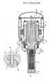
- a stirling cooler in accordance with the present invention comprises a case 50 provided with a cold tip 52 at an opened end thereof, a cylinder 54 fixedly installed in the case 50 and filled with a fluid, and a packing 70 positioned at a contact area between the case 50 and the cylinder 54 in an axial direction of the cylinder 54.
- a linear motor 56 is installed between the case 50 and an upper part of the cylinder 54, a piston 58 connected to the linear motor 56 is installed in the cylinder 54 such that the piston 58 can reciprocate, a displacer 62 supported by an elastic member 60 installed on the case 50 is installed in the piston 58 such that the displacer 62 can reciprocate, and a regenerator 64 is installed between the displacer 62 and the cold tip 52.
- a heat exchange chamber 66 is installed in the case 50 and the lower part of the cylinder 52, and communicates with the cylinder 52 and the regenerator 64 such that the heat exchange chamber 66 exchanges heat of the fluid with the cylinder 52 and the regenerator 64.
- An inner heat exchanger 68 is installed in the heat exchange chamber 66, and an outer heat exchanger 69 surrounding the heat exchange chamber 66 is installed on an outer surface of the case 50 so that the case 50 is interposed between the inner heat exchanger 68 and the outer heat exchanger 69.
- the heat exchange chamber 66 is configured such that two contact portions 53 and 53' of the cylinder 54, which are separated from each other in the axial direction of the cylinder 54, contact the case 50, and the lower contact portion 53' of the cylinder 54 has a width narrower than that of the upper contact portion 53 of the cylinder 54.
- the case 50 has a stepwise structure including two stairs 51 and 51' so that the upper stair 51 of the case 50 contacts the upper contact portion 53 of the cylinder 54 and the lower stair 51' of the case 50 contacts the lower contact portion 53' of the cylinder 54, thereby being provided with the heat exchange chamber 66.
- the fluid flows in the heat exchange chamber 66 between the cylinder 54 and the regenerator 64, and requires the packing 70 for maintaining a hermetically sealed state of the heat exchange chamber 66, inserting the cylinder 54 into a gap between the stairs 51 and 51' of the case 50 and preventing the change in an axis of the cylinder 54.
- the packing 70 is positioned at the upper stair 51 of the case 50.
- a flange 55 is protruded perpendicularly from the outer surface of the cylinder 54 in a radial direction, and seated on the upper stair 51 of the case 50 in the axial direction of the cylinder 54, and the packing 70 is interposed between the upper stair 51 of the case 50 and the flange 55 of the cylinder 54.
- the above packing 70 has a ring shape so that it is inserted into the whole outer circumference of the cylinder 54 for hermetically sealing the heat exchange chamber 66. Further, a radius of the packing 70, i.e., a distance from a center of the packing 70 to the outer circumference of the packing 70, is approximately the same as a distance from the center of the cylinder 54 to the flange 55 of the cylinder 54 in the radial direction of the cylinder 54.
- the flange 55 of the cylinder 54 has a ring shape. Therefore, the packing 70 and the flange 55 of the cylinder 54 have the same shape.
- the packing 70 includes through holes 71, into which the screws 80 are inserted, so that the packing 70 together with the cylinder 54 is fixed to the case 50.
- An O-ring 72 for firmly maintaining the sealed state of the heat exchange chamber 66 is positioned at the lower contact portion 53' of the cylinder 54.
- the O-ring 72 and the packing 70 are opposite to the heat exchange chamber 66 in the axial direction of the cylinder 54, thus maintaining the sealed state of the heat exchange chamber 66.
- an O-ring 74 for maintaining the sealed state of the inner heat exchanger 68 is positioned at the outer surface of the cylinder 54 located at the height of the heat exchange chamber 66.
- the heat exchange chamber 66 is firmly sealed by the packing 70 and the O-rings 72 and 74, the fluid filling the heat exchange chamber 66 cannot leak into spaces other than the regenerator 64.
- the cylinder 54 Since the packing 70 between the upper stair 51 of the case 50 and the flange 55 of the cylinder 54 is compressed in the axial direction of the cylinder 54, the cylinder 54 is easily assembled in the case 50. Further, the piston 58 and the displacer 62 reciprocate in the axial direction of the cylinder 54, thus improving the life span of the cylinder 54, the piston 58 and the displacer 62.
Landscapes
- Engineering & Computer Science (AREA)
- Mechanical Engineering (AREA)
- Thermal Sciences (AREA)
- General Engineering & Computer Science (AREA)
- Physics & Mathematics (AREA)
- Health & Medical Sciences (AREA)
- Emergency Management (AREA)
- Business, Economics & Management (AREA)
- General Health & Medical Sciences (AREA)
- Structural Engineering (AREA)
- Life Sciences & Earth Sciences (AREA)
- Geology (AREA)
- Public Health (AREA)
- Heat-Exchange Devices With Radiators And Conduit Assemblies (AREA)
- Fluid-Damping Devices (AREA)
- Sealing Devices (AREA)
- Compressors, Vaccum Pumps And Other Relevant Systems (AREA)
- Gasket Seals (AREA)
- Devices That Are Associated With Refrigeration Equipment (AREA)
- Filling Or Discharging Of Gas Storage Vessels (AREA)
- Details Of Heat-Exchange And Heat-Transfer (AREA)
Claims (6)
- Stirling-Kühleinrichtung, die umfasst:- ein Gehäuse (50), das an einem Ende mit einer kalten Spitze (52) versehen ist;- einen Zylinder (54), der in dem Gehäuse (50) fest installiert ist und mit einem Kolben (58) versehen ist, der sich darin hin und her bewegt;- einen Verdrängerkolben (62), der in dem Kolben (58) installiert ist, so dass sich der Verdrängerkolben hin und her bewegen kann;- einen Regenerator (64), der zwischen dem Verdrängerkolben (62) und der kalten Spitze (52) positioniert ist;- einen Wärmetauscher (68, 69), der mit dem Regenerator (64) und dem Zylinder (54) verbunden ist; und- eine Wärmetauscherkammer (66), die im Gehäuse (50) in einem unteren Teil des Zylinders (52) installiert ist;wobei der Wärmetauscher einen inneren Wärmetauscher (68), der in der Wärmetauscherkammer (66) installiert ist und zwischen dem Zylinder (54) und dem Gehäuse (50) positioniert ist, und einen äußeren Wärmetauscher (69), der an einer äußeren Oberfläche des Gehäuses gegenüber dem inneren Wärmetauscher (68) installiert ist, enthält;
dadurch gekennzeichnet, dass- eine Dichtung (70) an einer Seite der Wärmetauscherkammer (66) positioniert ist, um den dichten Zustand der Wärmetauscherkammer (66) in einem Bereich, in dem der Zylinder (54) in axialer Richtung des Zylinders (54) mit dem Gehäuse (50) in Kontakt ist, aufrecht zu erhalten;- ein O-Ring (72) an einer weiteren Seite der Wärmetauscherkammer (66) in einem Abschnitt des Zylinders (54), der mit dem Gehäuse (50) in radialer Richtung des Zylinders (54) in Kontakt ist, um die Wärmetauscherkammer (66) zu definieren, installiert ist, so dass der O-Ring (72) und die Dichtung (70) auf jeweils gegenüberliegenden Seiten der Wärmetauscherkammer (66) in axialer Richtung des Zylinders (54) positioniert sind; und- ein O-Ring (74) an einer äußeren Oberfläche des Zylinders (54) gegenüber dem inneren Wärmetauscher (68) installiert ist. - Stirling-Kühleinrichtung nach Anspruch 1, wobei die Dichtung (70) zwischen einem Flansch (55), der von einer äußeren Oberfläche des Zylinders (64) senkrecht vorsteht, und einer Stufe (51, 51') des Gehäuses (50), an der der Flansch (55) sitzt, eingefügt ist.
- Stirling-Kühleinrichtung nach Anspruch 2, wobei Durchgangslöcher (71) durch die Dichtung (70) ausgebildet sind, um den Flansch (55) des Zylinders (54) und die Stufe (51, 51') des Gehäuses (50) durch Schrauben (80) zu verbinden.
- Stirling-Kühleinrichtung nach Anspruch 2, wobei die Dichtung (70) eine Ringform hat, so dass sie in die äußere Oberfläche des Zylinders (54) eingesetzt ist.
- Stirling-Kühleinrichtung nach Anspruch 1, wobei- der Wärmetauscher (68, 69) eine innere und eine äußere Einheit umfasst, die an der Innenseite bzw. an der Außenseite der Wärmetauscherkammer (66) installiert sind, die zwischen dem Zylinder (54) und dem Gehäuse (50) positioniert ist und mit dem Regenerator (54) verbunden ist; und- die Dichtung (70) zwischen einem Flansch (55), der von einer äußeren Oberfläche des Zylinders (54) senkrecht vorsteht, und einer Stufe (51, 51') des Gehäuses (50), auf der der Flansch (55) in axialer Richtung des Zylinders (54) sitzt, eingefügt ist, um den dichten Zustand der Wärmetauscherkammer (66) aufrecht zu erhalten.
- Stirling-Kühleinrichtung nach Anspruch 5, wobei Durchgangslöcher (71) durch die Dichtung (70) ausgebildet sind, um den Flansch (55) des Zylinders (54) und die Stufe (51, 51') des Gehäuses (50) durch Schrauben (80) zu verbinden.
Applications Claiming Priority (2)
| Application Number | Priority Date | Filing Date | Title |
|---|---|---|---|
| KR2004005674 | 2004-01-29 | ||
| KR1020040005674A KR100565522B1 (ko) | 2004-01-29 | 2004-01-29 | 극저온 냉동기의 가스 누설 방지 구조 |
Publications (3)
| Publication Number | Publication Date |
|---|---|
| EP1559968A2 EP1559968A2 (de) | 2005-08-03 |
| EP1559968A3 EP1559968A3 (de) | 2006-06-07 |
| EP1559968B1 true EP1559968B1 (de) | 2009-11-18 |
Family
ID=34651532
Family Applications (1)
| Application Number | Title | Priority Date | Filing Date |
|---|---|---|---|
| EP04016097A Expired - Lifetime EP1559968B1 (de) | 2004-01-29 | 2004-07-08 | Stirling-Kühlanlage |
Country Status (6)
| Country | Link |
|---|---|
| US (1) | US20050166604A1 (de) |
| EP (1) | EP1559968B1 (de) |
| JP (1) | JP2005214610A (de) |
| KR (1) | KR100565522B1 (de) |
| CN (1) | CN100554822C (de) |
| DE (1) | DE602004024165D1 (de) |
Families Citing this family (3)
| Publication number | Priority date | Publication date | Assignee | Title |
|---|---|---|---|---|
| WO2012016192A2 (en) | 2010-07-30 | 2012-02-02 | Brooks Automation, Inc. | Multi-refrigerator high speed cryopump |
| US10156204B2 (en) * | 2017-04-24 | 2018-12-18 | Sunpower, Inc. | Attachment of cylinders in the housing of free-piston stirling machines |
| US10753653B2 (en) * | 2018-04-06 | 2020-08-25 | Sumitomo (Shi) Cryogenic Of America, Inc. | Heat station for cooling a circulating cryogen |
Family Cites Families (10)
| Publication number | Priority date | Publication date | Assignee | Title |
|---|---|---|---|---|
| US4130304A (en) * | 1977-08-12 | 1978-12-19 | Don R. Hinderliter, Inc. | Well head seal assembly |
| US4294600A (en) * | 1979-10-29 | 1981-10-13 | Oerlikon-Buhrle U.S.A. Inc. | Valves for cryogenic refrigerators |
| US4305741A (en) * | 1979-10-29 | 1981-12-15 | Oerlikon-Buhrle U.S.A. Inc. | Cryogenic apparatus |
| JPS59158960A (ja) * | 1983-03-02 | 1984-09-08 | 株式会社日立製作所 | 極低温冷凍機 |
| US4842287A (en) * | 1987-10-22 | 1989-06-27 | Helix Technology Corporation | Helium pressure seal for a cryogenic refrigerator |
| JPH04121557A (ja) * | 1990-09-10 | 1992-04-22 | Daikin Ind Ltd | 極低温冷凍機 |
| US6327862B1 (en) * | 2000-04-26 | 2001-12-11 | Superconductor Technologies, Inc. | Stirling cycle cryocooler with optimized cold end design |
| JP3643762B2 (ja) * | 2000-09-26 | 2005-04-27 | 三洋電機株式会社 | スターリング熱機器 |
| KR100831793B1 (ko) | 2002-02-04 | 2008-05-28 | 엘지전자 주식회사 | 쿨러 |
| US6694730B2 (en) * | 2002-05-30 | 2004-02-24 | Superconductor Technologies, Inc. | Stirling cycle cryocooler with improved magnet ring assembly and gas bearings |
-
2004
- 2004-01-29 KR KR1020040005674A patent/KR100565522B1/ko not_active Expired - Fee Related
- 2004-05-20 US US10/849,052 patent/US20050166604A1/en not_active Abandoned
- 2004-06-24 CN CNB2004100628534A patent/CN100554822C/zh not_active Expired - Fee Related
- 2004-07-02 JP JP2004197082A patent/JP2005214610A/ja active Pending
- 2004-07-08 EP EP04016097A patent/EP1559968B1/de not_active Expired - Lifetime
- 2004-07-08 DE DE602004024165T patent/DE602004024165D1/de not_active Expired - Lifetime
Also Published As
| Publication number | Publication date |
|---|---|
| JP2005214610A (ja) | 2005-08-11 |
| US20050166604A1 (en) | 2005-08-04 |
| EP1559968A3 (de) | 2006-06-07 |
| CN100554822C (zh) | 2009-10-28 |
| KR100565522B1 (ko) | 2006-03-30 |
| CN1648553A (zh) | 2005-08-03 |
| EP1559968A2 (de) | 2005-08-03 |
| DE602004024165D1 (de) | 2009-12-31 |
| KR20050078293A (ko) | 2005-08-05 |
Similar Documents
| Publication | Publication Date | Title |
|---|---|---|
| US6902381B2 (en) | Cylinder head for reciprocating compressor | |
| EP0372029B1 (de) | Tiefsttemperaturkälteanlage mit einem regenerator | |
| CN102844633B (zh) | 超低温制冷机 | |
| GB2258349A (en) | Conductive leaf springs in a linear motor. | |
| JP2933390B2 (ja) | 一体型スターリングクリオクーラ用のシール構造体 | |
| US6993917B2 (en) | Coupling for heat transfer member | |
| US6092999A (en) | Reciprocating compressor with a linear motor | |
| JP3855225B2 (ja) | フリーピストン・スターリング装置のケーシング | |
| EP1559968B1 (de) | Stirling-Kühlanlage | |
| US4712378A (en) | Driving apparatus for stirling cycle engine | |
| EP1562008B1 (de) | Stirling-Kühlanlage und zugehöriger Wärmetauscher | |
| KR20210002651A (ko) | 밀폐형 압축기, 및 밀폐형 압축기의 제조 방법 | |
| JPH09236343A (ja) | 極低温冷却装置 | |
| JPS6057167A (ja) | 極低温冷凍機 | |
| CN220750437U (zh) | 气动斯特林制冷机 | |
| JP2591220B2 (ja) | 逆スターリングサイクル冷凍機の膨脹器 | |
| JP3756982B2 (ja) | 多段圧縮装置 | |
| JP2019015489A (ja) | 極低温冷凍機 | |
| JPH0771834A (ja) | 極低温冷凍機 | |
| JP2003028527A (ja) | スターリング機関用内部熱交換器及びスターリング冷凍機 | |
| JP2000179964A (ja) | 冷凍機用コールドヘッド | |
| GB2179705A (en) | Piston and cylinder arrangement in stirling engine | |
| JPH0784962B2 (ja) | 極低温冷凍機の給排気装置 | |
| JP2007205582A (ja) | 蓄冷器式冷凍機 | |
| JPH09159299A (ja) | スターリングサイクル式多段冷凍機 |
Legal Events
| Date | Code | Title | Description |
|---|---|---|---|
| PUAI | Public reference made under article 153(3) epc to a published international application that has entered the european phase |
Free format text: ORIGINAL CODE: 0009012 |
|
| 17P | Request for examination filed |
Effective date: 20040708 |
|
| AK | Designated contracting states |
Kind code of ref document: A2 Designated state(s): AT BE BG CH CY CZ DE DK EE ES FI FR GB GR HU IE IT LI LU MC NL PL PT RO SE SI SK TR |
|
| AX | Request for extension of the european patent |
Extension state: AL HR LT LV MK |
|
| PUAL | Search report despatched |
Free format text: ORIGINAL CODE: 0009013 |
|
| AK | Designated contracting states |
Kind code of ref document: A3 Designated state(s): AT BE BG CH CY CZ DE DK EE ES FI FR GB GR HU IE IT LI LU MC NL PL PT RO SE SI SK TR |
|
| AX | Request for extension of the european patent |
Extension state: AL HR LT LV MK |
|
| AKX | Designation fees paid |
Designated state(s): DE FR GB NL |
|
| 17Q | First examination report despatched |
Effective date: 20071128 |
|
| GRAP | Despatch of communication of intention to grant a patent |
Free format text: ORIGINAL CODE: EPIDOSNIGR1 |
|
| GRAS | Grant fee paid |
Free format text: ORIGINAL CODE: EPIDOSNIGR3 |
|
| GRAA | (expected) grant |
Free format text: ORIGINAL CODE: 0009210 |
|
| AK | Designated contracting states |
Kind code of ref document: B1 Designated state(s): DE FR GB NL |
|
| REG | Reference to a national code |
Ref country code: GB Ref legal event code: FG4D |
|
| REF | Corresponds to: |
Ref document number: 602004024165 Country of ref document: DE Date of ref document: 20091231 Kind code of ref document: P |
|
| PLBE | No opposition filed within time limit |
Free format text: ORIGINAL CODE: 0009261 |
|
| STAA | Information on the status of an ep patent application or granted ep patent |
Free format text: STATUS: NO OPPOSITION FILED WITHIN TIME LIMIT |
|
| 26N | No opposition filed |
Effective date: 20100819 |
|
| PGFP | Annual fee paid to national office [announced via postgrant information from national office to epo] |
Ref country code: NL Payment date: 20100729 Year of fee payment: 7 |
|
| PGFP | Annual fee paid to national office [announced via postgrant information from national office to epo] |
Ref country code: DE Payment date: 20100730 Year of fee payment: 7 |
|
| REG | Reference to a national code |
Ref country code: NL Ref legal event code: V1 Effective date: 20120201 |
|
| PG25 | Lapsed in a contracting state [announced via postgrant information from national office to epo] |
Ref country code: DE Free format text: LAPSE BECAUSE OF NON-PAYMENT OF DUE FEES Effective date: 20120201 |
|
| REG | Reference to a national code |
Ref country code: DE Ref legal event code: R119 Ref document number: 602004024165 Country of ref document: DE Effective date: 20120201 |
|
| PG25 | Lapsed in a contracting state [announced via postgrant information from national office to epo] |
Ref country code: NL Free format text: LAPSE BECAUSE OF NON-PAYMENT OF DUE FEES Effective date: 20120201 |
|
| REG | Reference to a national code |
Ref country code: FR Ref legal event code: PLFP Year of fee payment: 13 |
|
| PGFP | Annual fee paid to national office [announced via postgrant information from national office to epo] |
Ref country code: GB Payment date: 20160615 Year of fee payment: 13 |
|
| PGFP | Annual fee paid to national office [announced via postgrant information from national office to epo] |
Ref country code: FR Payment date: 20160615 Year of fee payment: 13 |
|
| GBPC | Gb: european patent ceased through non-payment of renewal fee |
Effective date: 20170708 |
|
| REG | Reference to a national code |
Ref country code: FR Ref legal event code: ST Effective date: 20180330 |
|
| PG25 | Lapsed in a contracting state [announced via postgrant information from national office to epo] |
Ref country code: GB Free format text: LAPSE BECAUSE OF NON-PAYMENT OF DUE FEES Effective date: 20170708 |
|
| PG25 | Lapsed in a contracting state [announced via postgrant information from national office to epo] |
Ref country code: FR Free format text: LAPSE BECAUSE OF NON-PAYMENT OF DUE FEES Effective date: 20170731 |