EP1562261A2 - Element de fixation creux pour attachement à une plaque métallique et pièce d'assemblage - Google Patents
Element de fixation creux pour attachement à une plaque métallique et pièce d'assemblage Download PDFInfo
- Publication number
- EP1562261A2 EP1562261A2 EP05010275A EP05010275A EP1562261A2 EP 1562261 A2 EP1562261 A2 EP 1562261A2 EP 05010275 A EP05010275 A EP 05010275A EP 05010275 A EP05010275 A EP 05010275A EP 1562261 A2 EP1562261 A2 EP 1562261A2
- Authority
- EP
- European Patent Office
- Prior art keywords
- fastener
- sheet metal
- metal part
- rivet
- annular
- Prior art date
- Legal status (The legal status is an assumption and is not a legal conclusion. Google has not performed a legal analysis and makes no representation as to the accuracy of the status listed.)
- Granted
Links
Images





Classifications
-
- F—MECHANICAL ENGINEERING; LIGHTING; HEATING; WEAPONS; BLASTING
- F16—ENGINEERING ELEMENTS AND UNITS; GENERAL MEASURES FOR PRODUCING AND MAINTAINING EFFECTIVE FUNCTIONING OF MACHINES OR INSTALLATIONS; THERMAL INSULATION IN GENERAL
- F16B—DEVICES FOR FASTENING OR SECURING CONSTRUCTIONAL ELEMENTS OR MACHINE PARTS TOGETHER, e.g. NAILS, BOLTS, CIRCLIPS, CLAMPS, CLIPS OR WEDGES; JOINTS OR JOINTING
- F16B37/00—Nuts or like thread-engaging members
- F16B37/04—Devices for fastening nuts to surfaces, e.g. sheets, plates
- F16B37/06—Devices for fastening nuts to surfaces, e.g. sheets, plates by means of welding or riveting
- F16B37/062—Devices for fastening nuts to surfaces, e.g. sheets, plates by means of welding or riveting by means of riveting
-
- F—MECHANICAL ENGINEERING; LIGHTING; HEATING; WEAPONS; BLASTING
- F16—ENGINEERING ELEMENTS AND UNITS; GENERAL MEASURES FOR PRODUCING AND MAINTAINING EFFECTIVE FUNCTIONING OF MACHINES OR INSTALLATIONS; THERMAL INSULATION IN GENERAL
- F16B—DEVICES FOR FASTENING OR SECURING CONSTRUCTIONAL ELEMENTS OR MACHINE PARTS TOGETHER, e.g. NAILS, BOLTS, CIRCLIPS, CLAMPS, CLIPS OR WEDGES; JOINTS OR JOINTING
- F16B37/00—Nuts or like thread-engaging members
- F16B37/04—Devices for fastening nuts to surfaces, e.g. sheets, plates
- F16B37/06—Devices for fastening nuts to surfaces, e.g. sheets, plates by means of welding or riveting
- F16B37/062—Devices for fastening nuts to surfaces, e.g. sheets, plates by means of welding or riveting by means of riveting
- F16B37/065—Devices for fastening nuts to surfaces, e.g. sheets, plates by means of welding or riveting by means of riveting by deforming the material of the nut
-
- F—MECHANICAL ENGINEERING; LIGHTING; HEATING; WEAPONS; BLASTING
- F16—ENGINEERING ELEMENTS AND UNITS; GENERAL MEASURES FOR PRODUCING AND MAINTAINING EFFECTIVE FUNCTIONING OF MACHINES OR INSTALLATIONS; THERMAL INSULATION IN GENERAL
- F16B—DEVICES FOR FASTENING OR SECURING CONSTRUCTIONAL ELEMENTS OR MACHINE PARTS TOGETHER, e.g. NAILS, BOLTS, CIRCLIPS, CLAMPS, CLIPS OR WEDGES; JOINTS OR JOINTING
- F16B37/00—Nuts or like thread-engaging members
- F16B37/04—Devices for fastening nuts to surfaces, e.g. sheets, plates
- F16B37/06—Devices for fastening nuts to surfaces, e.g. sheets, plates by means of welding or riveting
- F16B37/062—Devices for fastening nuts to surfaces, e.g. sheets, plates by means of welding or riveting by means of riveting
- F16B37/068—Devices for fastening nuts to surfaces, e.g. sheets, plates by means of welding or riveting by means of riveting by deforming the material of the support, e.g. the sheet or plate
-
- H—ELECTRICITY
- H01—ELECTRIC ELEMENTS
- H01R—ELECTRICALLY-CONDUCTIVE CONNECTIONS; STRUCTURAL ASSOCIATIONS OF A PLURALITY OF MUTUALLY-INSULATED ELECTRICAL CONNECTING ELEMENTS; COUPLING DEVICES; CURRENT COLLECTORS
- H01R4/00—Electrically-conductive connections between two or more conductive members in direct contact, i.e. touching one another; Means for effecting or maintaining such contact; Electrically-conductive connections having two or more spaced connecting locations for conductors and using contact members penetrating insulation
- H01R4/28—Clamped connections, spring connections
- H01R4/30—Clamped connections, spring connections utilising a screw or nut clamping member
- H01R4/305—Clamped connections, spring connections utilising a screw or nut clamping member having means for facilitating engagement of conductive member or for holding it in position
-
- H—ELECTRICITY
- H01—ELECTRIC ELEMENTS
- H01R—ELECTRICALLY-CONDUCTIVE CONNECTIONS; STRUCTURAL ASSOCIATIONS OF A PLURALITY OF MUTUALLY-INSULATED ELECTRICAL CONNECTING ELEMENTS; COUPLING DEVICES; CURRENT COLLECTORS
- H01R4/00—Electrically-conductive connections between two or more conductive members in direct contact, i.e. touching one another; Means for effecting or maintaining such contact; Electrically-conductive connections having two or more spaced connecting locations for conductors and using contact members penetrating insulation
- H01R4/58—Electrically-conductive connections between two or more conductive members in direct contact, i.e. touching one another; Means for effecting or maintaining such contact; Electrically-conductive connections having two or more spaced connecting locations for conductors and using contact members penetrating insulation characterised by the form or material of the contacting members
- H01R4/64—Connections between or with conductive parts having primarily a non-electric function, e.g. frame, casing, rail
-
- Y—GENERAL TAGGING OF NEW TECHNOLOGICAL DEVELOPMENTS; GENERAL TAGGING OF CROSS-SECTIONAL TECHNOLOGIES SPANNING OVER SEVERAL SECTIONS OF THE IPC; TECHNICAL SUBJECTS COVERED BY FORMER USPC CROSS-REFERENCE ART COLLECTIONS [XRACs] AND DIGESTS
- Y10—TECHNICAL SUBJECTS COVERED BY FORMER USPC
- Y10T—TECHNICAL SUBJECTS COVERED BY FORMER US CLASSIFICATION
- Y10T29/00—Metal working
- Y10T29/49—Method of mechanical manufacture
- Y10T29/49002—Electrical device making
- Y10T29/49117—Conductor or circuit manufacturing
- Y10T29/49204—Contact or terminal manufacturing
- Y10T29/49208—Contact or terminal manufacturing by assembling plural parts
-
- Y—GENERAL TAGGING OF NEW TECHNOLOGICAL DEVELOPMENTS; GENERAL TAGGING OF CROSS-SECTIONAL TECHNOLOGIES SPANNING OVER SEVERAL SECTIONS OF THE IPC; TECHNICAL SUBJECTS COVERED BY FORMER USPC CROSS-REFERENCE ART COLLECTIONS [XRACs] AND DIGESTS
- Y10—TECHNICAL SUBJECTS COVERED BY FORMER USPC
- Y10T—TECHNICAL SUBJECTS COVERED BY FORMER US CLASSIFICATION
- Y10T29/00—Metal working
- Y10T29/49—Method of mechanical manufacture
- Y10T29/49826—Assembling or joining
- Y10T29/49908—Joining by deforming
- Y10T29/49938—Radially expanding part in cavity, aperture, or hollow body
- Y10T29/49943—Riveting
Definitions
- the present invention relates to a method for producing a electrically conductive connection between a, having a recess electrical connection device such as a cable lug and a sheet metal part, in which a hollow fastening element with the sheet metal part is riveted against rotation and thereby an electrically conductive connection between fastener and sheet metal part is generated and so assembled component subsequently produced with an electrically not conductive or poorly conductive protective coating, such as a lacquer layer or a powder coating is provided. Further The invention relates to a fastener for applying the method and an assembly part consisting of the fastener and a sheet metal part.
- a fastener of the type mentioned is, for example from EP-A-539743.
- the assembly part which arises when the fastener attached to a sheet metal part can, according to the beginning said method with a protective coating, such as a lacquer layer or powder coating, be provided.
- a protective coating such as a lacquer layer or powder coating
- the nut member according to EP-A-539793 can not be self-piercing in a Sheet metal part are introduced, but the sheet metal part must be pre-punched. Furthermore, the sheet preparation in EP-A-539793 comprises the Generation of an axially projecting annular lip in the sheet metal part, the one Limited opening in which the rivet portion of the fastener must be brought into it. This operation raises the lip of the ring the side of the sheet metal part from which introduced the fastener becomes.
- the protruding lip with the prefabricated opening means in the Practice that the fastener with high accuracy with respect to the sheet metal part must be aligned to ensure proper attachment to ensure the fastener.
- the object of the present invention is a method or a fastening element and an assembly part of the type mentioned so to improve that a high quality electrical connection between the electrical connection device and the sheet metal part cost is achievable without the protective coating quality impaired the electrical connection and without consuming Measures must be taken to protect the protective coating remove.
- a method of the initially provided that it is characterized in that Area of the front side of the fastener on which the electrical Attachment is attached, a receptacle for the electrical Connection device is formed, which is a rotation of the connection device relative to the fastening element or the sheet metal part prevents and that a thread forming or cutting Screw through the recess of the electrical connection device and is screwed into the hollow fastener and there by the screwing forms a thread or cuts.
- a fastening element for the electrical conductive attachment of an electrical connection device such as a Lug to a sheet metal part provided that is characterized by the hollow fastener has a head portion and a rivet portion wherein the rivet portion has a contact surface for the Sheet metal part in the head part passes and anti-rotation features on the Abutment surface and / or provided on the rivet section, wherein the hollow Fastener has a smooth cylinder bore at one point, at the a thread by screwing a thread or cutting Forming screw is formed and that at the rivet section facing away from the front side of the head part a receptacle for the torsion Attachment of the electrical connection device to the fastening element is provided.
- a fastener By attaching such a fastener to a sheet metal part arises according to the invention then consists of an assembly part from a sheet metal part and attached to this via a riveted joint hollow fastener, wherein the fastener secured against rotation by means of anti-rotation features on the sheet metal part is and the fastener and the sheet metal part together with a electrically non-conductive or poorly conductive protective coating are coated and an electrically conductive path between the fastener and the sheet metal part in the region of the riveted joint and / or the anti-rotation features is provided.
- the assembly part is characterized in that the fastener is a smooth Cylinder bore for receiving a thread forming or cutting Has screw and that facing away from the rivet connection Front side of the fastener of this a receptacle for the having a rotationally secure attachment of the electrical connection device.
- the fastener is preferably self-stamping to the sheet metal part appropriate. That is, either the rivet portion as a punching and riveting section may be formed or a tubular part of the fastener used as a punching device in the area of the rivet section can be used to punch a hole in the sheet metal part.
- the power the is required to perform the punching process, for example as usual when attaching fasteners to sheet metal parts be supplied by a press, responsible for the implementation of the attachment process or by a robot or something else Tools are provided.
- fasteners in self-piercing versions has not only the Advantage that this is a step in the sense of pre-perforation of the Sheet metal part can be avoided, but the punching process ensures clean metallic surfaces on the fastening element and on the sheet metal part, for a low contact resistance between the fastener and the sheet metal part, i. for a high quality electrical connection in the appropriate places.
- the protective coating completely covers the outside Surface areas of the fastener and also penetrates often the bore of the hollow fastener, especially then, if electrostatic aids are used during painting.
- the mentioned hole strictly must not be generated by a drilling tool, but could also be by cold cutting tools or by punching or be generated elsewhere.
- the term bore should therefore be interpreted as meaning that they are not limited to a particular manufacturing process is.
- the electrically conductive connection thus leads from the electrical connection device over the screw in the fastener in Area of the thread into and from the metallic fastener about the anti-rotation features and surface areas in the area of the punch hole in the sheet metal part in the sheet metal part.
- the sheet metal part is usually then installed in a body or in a housing, which can be referred to as mass.
- This requirement is a fastener, which is characterized characterized in that that a tubular guide portion concentric to the tubular rivet and arranged radially inside this is, wherein between the guide portion and the rivet portion a Annular gap is provided and the guide section over the free end protrudes the rivet section.
- this Vorlochung can also so be made that on the side of the sheet, from which the fastener is introduced, no protruding annular lip is present, which also the orientation of the fastener with the sheet metal part facilitated.
- the guide section of the fastener formed as a punching section can be, whereby the fastener self-piercing in the Sheet metal part can be introduced so that a pre-punching at all is not necessary and the demands on the orientation of the fastener be even lower with the sheet metal part.
- DE-C-3446978 describes inter alia Nut element which is introduced into a sheet-metal part by self-stamping
- DE-C-3447006 discloses a similarly designed bolt element.
- the nut member nor the bolt member according to the above German patents mentioned has a leadership section in addition to the rivet section, so that the rivet section both the punching function as also has to perform the riveting function, which is more complicated and ultimately stricter requirements for the rivet section and the used Die poses, as in the above-mentioned arrangement with separate Riveting and punching sections is the case.
- a fastener with a punching and riveting section for the purpose of the present Be exploited invention, as will be explained later.
- the free end of the wall of the annular Rivet section seen in an axial sectional plane, both rounded on the radially outer side as well as on the radially inner side is and, for example, a semi-circular or arrowhead-like shape having.
- the guide portion of the fastening element leads when attaching the fastener to a sheet metal part a cone-shaped depression in the sheet metal part, namely a pre-punched Sheet metal part in the expansion of the hole through the guide section and in a self-piercing embodiment of the fastener before the cutting out of a stamped by the as Stamped portion formed guide portion, wherein the cone-shaped Well then the rivet section is widened.
- the rounded education the outer wall of the rivet section in the area of his free end is a favorable shape for the further expansion of the hole and the corresponding deformation of the conical wall of the Deepening.
- the rounded shape on the inner side of the free end of the Nietabiteses helps against it when flanging the rivet section, which takes place in a correspondingly concavely curved annular surface of the die.
- This shape also allows the annular gap to be as small as possible can be held without the process of flanging the rivet section to impair. Characterized in that the annular gap as small as possible can be held and even 0 mm (which means that the inner wall of the rivet section on the outer periphery of Guide portion rests), the diameter of the fastener as a whole are kept as small as possible, creating material Saved and costs can be reduced.
- the annular gap preferably has a radial dimension in the range between 0 mm and about 3 mm.
- the annular gap is preferably at an axial distance in front of the annular Contact surface on the Nietabitessseite the annular bearing surface over.
- the guide portion is formed as a punching section, it has preferably an annular cutting edge at its contact surface facing away from the front end and this cutting edge acts with a corresponding shaped cutting edge of a central bore of a die together to get a clean punch from the sheet metal part at the To punch out attachment of the fastening element on the sheet metal part.
- anti-rotation features in the range the annular bearing surface and / or at the rivet and / or at the lateral surface of the head part adjacent to the support surface are. If the anti-rotation features in the area of the lateral surface of the head part are provided, these can be replaced by a polygonal or grooved shape of the lateral surface are generated.
- the anti-rotation features in the area of the annular bearing surface and / or on the rivet section and optionally on the lateral surface can by noses or be formed by groove-shaped depressions.
- anti-rotation lugs are provided, they can exalted the contact surface and the rivet section in the area of the transition from the bearing surface in the rivet section are present.
- the receptacle for the electrical connection device is preferably by at least one over the end face of the fastener formed protruding projection.
- Lappen trained projection to a rotation of the electric Connection device for example in the form of a cable lug to prevent, since with initial rotation of the cable lug of the connection area for the cable then in abutment against a flank of the projection or the lobe device and a further rotation of the electrical Connection device prevents. It is even cheaper if that Fastener with two protrusions is executed by two spaced apart flaps are formed, the are arranged laterally of the bore of the hollow fastening element.
- the area of the cable lug, which receives the cables, can then between the two lobes are positioned and the relative rotation between the cable lug and the fastener to a minimum be limited by the distance between the two lobes is determined.
- the two lobes are two open Created areas in which the cable connection area of the cable lug can be optionally arranged.
- Projections are provided, creating several open areas between each two lobes are created so that several possible Orientations of a cable lug are present.
- the projection may extend around the bore of the fastener extend around and are polygonal running in the outer contour.
- outside outlines come in triangular, square, hexagonal or octagonal shape in question, the octagonal shape is particularly preferred because it has several possible orientations of a suitably trained cable lug permits.
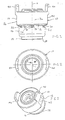
- the fastener shown there 10 having a an annular bearing surface 12 having Head part 14 and a tubular on the side of the support surface 12 of the Head portion 14 provided extending away from the head part 14 rivet section 16 provided.
- the fastening element has a central longitudinal axis 11 on.
- a tubular guide portion 18 is concentric with the tubular Rivet section 16 and disposed radially within this, wherein between the guide portion 18 and the rivet portion 16 an annular gap 20 is provided, which is visible only in Fig. 4.
- the free end 22 of the wall of the annular rivet section 16 in the axial sectional plane of FIG. 4 seen both on the radially outer side 24 and on the radial rounded on the inner side 26 and has a rounded arrowhead here Shape.
- the tip of the arrowhead-like shape could also be rounded which would result in a semi-circular shape, but which not shown.
- the annular gap has a radial dimension from 0 mm, i. the rivet section rests against the guide section 18, but is only connected to the guide section 18 where the annular gap 20 at a short axial distance "a" in front of the annular bearing surface 12 comes to an end.
- the fastener of Figures 1 to 4 is usually by a Cold impact method produced, the basic features of which are well known are.
- the rivet section lying close to the guide section It may be necessary, the rivet section only with a certain radial distance from the guide section to produce by cold hammering and subsequently in another phase of the cold-striking process to press the rivet section to the guide section or the To widen guide section to the rivet section up to the plant or the reduction of the radial distance by a combination of the to achieve both measures. It is favorable if the annular gap 20 has the smallest possible radial width, as this leads to a compact Training the fastener leads and saves material.
- the guide portion 18 is formed here as a punching section and has an annular cutting edge 28 at its support surface 12th facing away from the end, i. at his free end.
- FIGS. 1 to 4 furthermore show anti-rotation features 30 in FIG Area of the annular bearing surface 12 and the rivet 16 on wherein the anti-rotation features are formed by lugs, the raised on the support surface 12 and the rivet 16 in the region of Transition from the support surface in the rivet 16 are present.
- the Anti-rotation lugs shown here are with side edges 30 and 32nd provided in the longitudinal direction of the element extending planes lie.
- the formed in Fig. 1 and 4 at 34 and 36 sharp-edged Anti-rotation lugs can instead be here with rounded edges be provided.
- the anti-rotation noses could also by depressions be realized in the support surface or in the rivet section.
- the possibility of the lateral surface 36 of the head part 14 would be a to give polygonal or grooved shape.
- the hollow fastener has a smooth cylinder bore coaxial with the longitudinal axis 11 of the Fastener is arranged and in this example partially in Guide section 18 is present.
- the diameter of the smooth cylinder bore is such that by screwing a thread cutting or thread forming Screw, as will be explained in more detail with reference to FIG. 15, a thread of the desired size is created.
- a thread of the desired size is created.
- an M8 thread is for example, the diameter of 7.55 for a thread forming Screw selected.
- thread cutting screws can also the commonly given dimensions are selected.
- FIG. 1 to 4 Another feature of the hollow fastener of Figures 1 to 4 can be seen in the two lobes 40, from the upper end of the Element 10 protrude and are generated by the fact that the cold impact method Material from areas 42 pushed up is so that arise at the points 42 corresponding wells, where the term "up" only in terms of representation 1 and how other locations in this Registration is only based on the figures used and no spatial Restriction of the subject invention represents.
- the rags 40 ensure that a cable lug on the fastener by means a screw inserted from above can be fastened without the cable lug is turned with the screw when attaching the screw is, since a co-rotation of the cable lug through the lobes 40th is prevented.
- the an electrical connection device performing cable lug can a provided as an eyelet pad, which is a circular recess for receiving the mentioned screw or a likewise have known U-shaped recess through two connecting legs are limited. In both cases, one is from the pad provided laterally wegeruitender connection area, which is a cable usually holds a crimp connection with this connection area Power is fixed conductively.
- the exact training of electrical connection device is not on such versions limited and may in principle have any shape, including the shape of sheet metal parts, such as those from a Housing an electrical device protrude, as exemplified in Fig. 15 and 16 are shown. It should only the shape of the recording on the fastener with the shape of the electrical connection device thereby be compatible, that achieves the desired rotation becomes.
- the fastening element 10 cylindrical clearances or recesses 44 and 46 above and below the smooth cylinder bore 38, these free spaces have a diameter that usually sized slightly larger is called the outside diameter of a bolt that enters the cylinder bore 38 is screwed.
- the cylinder bore 38 here partially in the head part 14 and partially is arranged in the guide section 18 of the fastening element 10, It could also be completely in the head section or completely in the guide section to be ordered.
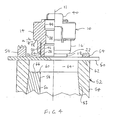
- Fig. 4 shows the fastener 10 in a first stage of Attachment to a sheet metal part 50, wherein in the illustration of FIG. 4 the Sheet metal part 50 is supported on a die 52 and against the die 52nd is pressed by means of an annular hold-down 54, wherein the Downholder 54 preferably, but not necessarily be provided got to.
- FIG. 4 assumes that the attachment of the Fastener 10 is carried on the sheet metal part 50 in a press, wherein the die 52 is located in the lower die of the press (not also shown) and the fastener 10 by means of a not shown setting head is pressed onto the sheet metal part 50, wherein the setting head on an intermediate plate of the press or on an upper tool the press can be attached.
- Such setting heads and hold-down 54 are well known in the art and therefore are not here extra described. It should, however, be expressed that Other arrangements within a press are possible.
- the die 52 may be placed in an intermediate plate of the press be, with the setting head with or without hold then on upper tool of the press is attached.
- a two-part design of the die 52 is shown. These consists of an outer ring-shaped female part 54 and an inner, also annular die part 56 with a central longitudinal bore 58, in this example, the inner female part 56 a light has conically extending outer wall, with a corresponding shaped cone-shaped inner wall 53 of the outer Matrices part 54 cooperates, so that the upper end face 60 of the inner female part 56 below the upper end face 62 of the outer Matrizenteils 54 comes to rest and thereby forms a recess 64.
- the upper end 60 of the inner female part 56 thus forms the Bottom surface of the recess 64 and otherwise has an annular concave surface 66 on.
- the central bore 58 of the middle Die member 56 has a diameter that is slightly larger as the outer diameter of the guide portion 18.
- the recess 64 has a diameter that is slightly larger than the outer diameter the head portion 14 of the fastener 10 plus the double thickness of sheet metal part 50.
- Both the inner female part 56 and its bore 58, and also the outer female part 54 and between the two Matrizenized recess 64, are coaxial with the central longitudinal axis 11 of the Fastener 10 is arranged.
- the template 52 could also be one-piece be executed.
- the guide portion 18 has a Punch 74 from the bottom of the cone-shaped recess of the sheet metal part separated out and this partially through the central bore 58th pressed the die, with this central bore 58 also slightly after may be formed divergent below, so that the punched over this central longitudinal bore by gravity, optionally with pneumatic support, can be disposed of.
- Head portion 14 of the fastener 10 is a polygonal or grooved or ribbed shape, so also in this area is a corresponding Positive locking between the sheet metal part and the fastener generated.
- the finished assembly part consisting of the fastener 10 and the sheet metal part 50, is then shown in Fig. 8, according to the Removal from the attachment tool, d. H. from the press or from the robot or otherwise designed attachment tools.
- an electrical connection device for example a Cable lug
- the assembly part as a whole provided with a protective coating and an electrical connection device, for example a Cable lug, can then on the upper front side of the fastener or fastened to the lower end face of FIG. 8, i.e. the corresponding thread cutting or thread forming Screw can come from the top into the cylinder bore at the same time Training the threaded cylinder are introduced.
- the rags 40 provided here allow the element as electrical Connection element can be used, for example as a ground connection element in a vehicle body.
- the fastener 10 has the particular advantage that it also with protective layers or paint layers provided sheet metal parts 50 can be used and yet a produces excellent electrical connection, in the area of Punching holes and anti-rotation noses straight at a sharp-edged Training the anti-rotation noses the protective coating cut locally and for a metallic connection to the Sheet metal part 50 provide.
- the protective layer becomes in places damaged within the positive connection between the sheet metal part 50th and the fastener lie so that there is a seal and corrosion is prevented.
- the positive connection between the sheet metal part and the fastener is so intense that the connection a sealed connection, which, when it comes to a special seal arrives also by applying an adhesive to the element or the sheet metal part can be supported.
- the item Due to the depression in the Sheet metal part 50 in the region of the fastener is an excellent Ensured connection with the sheet metal part, so that a high resistance against pull-out forces in both directions and a high Ausknüpfwiderstand is generated and also a high resistance against Shearing forces and torsional forces is present. Also, the item can be at alternating dynamic loads are used and signs of fatigue with dynamic loads are not to be feared.
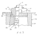
- FIGS. 9 to 15 deal with a further invention Execution of a fastener 10, which is the fastener of Fig. 1 to 8 is very similar. There are essentially only two differences which will be described in more detail later.
- FIGS. 9 to 15 and the other figures are the same reference numerals as used for the first embodiment According to Fig. 1 to 8 and it is understood that parts or features that the have the same reference numerals, have the same function as in the first embodiment. In this respect, the previous description applies to the examples below, unless it becomes otherwise said.
- the fastener according to Fig. 9 to 15 mainly two differences from the previous one Identify embodiment according to Figures 1 to 8. It is here once around the annular abutment surface 12, which in this example is cone-shaped is arranged and an included cone angle of 90 ° forms on the central longitudinal axis 11 of the fastener.
- the Anti-rotation features are located exclusively in this example in the region of the annular contact surface 12.
- the fastening element 10 of the embodiment of FIG. 9 to 15 is just as on a Sheet metal part attached as in the first embodiment, only is the Die slightly modified to take into account the cone-shaped bearing surface. Further information on the advantages and design of the fastener with a cone-shaped sheet metal surface are the PCT application PCT / EP02 / 04365 of the present applicant.
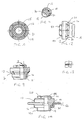
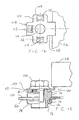
- the receptacle 80 is for recording the electrical connection device 104 in this example by a Projection 41 is formed, which from the upper end side of the fastener 10, which faces away from the rivet section 16, protrudes.
- This Projection has a central bore coaxial with the central bore 38 of the hollow fastener 10 is slightly larger in diameter larger than the bore 38 is.
- the electrical connection device as Sheet metal part formed with a recess 110 in the form of a through hole, through which the screw 106 protrudes and with three, in the representation of FIG.
- the electrical Connecting device 104 as a terminal of a housing 116th an electrical unit of any type provided.
- the electric But connecting device 104 could just as well with a cable connection area be formed, on which one or more cables through a crimp is attached or are.
- the Area 118 serve this purpose.
- the exposed surfaces of the assembly part, consisting of the Sheet metal part 50 of the fastener 10 of FIG. 15 including Outer sides and upper end face of the projection 41 are, as well as in the other examples of the assembly part, with a protective coating 120 coated (only indicated in places and not in Fig. 8) yet) is a high quality electrical connection between the electrical connection device 104 and the sheet metal part 50 exists, and indeed this connection leads from the electrical Connecting device over the head of the screw 106, the shaft part of the Screw 106 and that of this screw shaped or cut Thread in the fastener and continue on the fastener itself and the anti-rotation features and punching surfaces in the sheet metal part 50 inside.
- the protective coating on the surface of the Projection 41 thus does not prevent a high-quality electrical Connection is made.
- the fastener 10 of FIGS. 17 to 19 is according to the European patent EP 0 539 793, only here is the rivet section 16 formed as a punching and riveting according to the Description of DE 3446978 C and DE 3447006 C.
- a receptacle 80 for an electrical connection device corresponding to the receptacle 80 of the embodiment of FIG. 9 to 15 is formed and therefore an octagonal outline in the outer contour 41 has.
- the fastener 10 in This example also with two lobes corresponding to the lobes 40 of Embodiment according to FIGS. 1 to 8 are provided.
- the present invention is not limited to the fastening elements, shown in the figures, but each hollow fastener, that on a sheet metal part with a sufficiently high security against rotation and detachment security can be attached by the provision of a corresponding receptacle for an electrical connection device used according to the invention.
- the fasteners described here may, for example all materials which have the strength class 5.6 or reach higher.
- Such metal materials are usually carbon steels with 0.15 to 0.55% carbon content.
- the fasteners are called all the materials in the frame the cold deformation the strength values of class 8 according to ISO standard reach, for example, a 35B2 alloy according to DIN 1654.
- the so formed fasteners are u.a. for all commercial Steel materials for drawable sheet metal parts as well as for aluminum or its alloys.
- aluminum alloys, in particular those with high strength, used for the fasteners be, e.g. AlMg5.
- fasteners come from higher strength Magnesium alloys such as AM50 in question.
Landscapes
- Engineering & Computer Science (AREA)
- General Engineering & Computer Science (AREA)
- Mechanical Engineering (AREA)
- Connection Of Plates (AREA)
- Insertion Pins And Rivets (AREA)
- Multi-Conductor Connections (AREA)
- Cylinder Crankcases Of Internal Combustion Engines (AREA)
Applications Claiming Priority (3)
| Application Number | Priority Date | Filing Date | Title |
|---|---|---|---|
| DE10243759 | 2002-09-20 | ||
| DE10243759A DE10243759B4 (de) | 2002-09-20 | 2002-09-20 | Verfahren zur Erzeugung einer elektrisch leitenden Verbindung zwischen einer elektrischen Anschlusseinrichtung wie ein Kabelschuh und einem Blechteil, Befestigungselement und Zusammenbauteil |
| EP03807744A EP1540770B1 (fr) | 2002-09-20 | 2003-07-09 | Elément de fixation creux pour une installation électriquement conductrice d'une pièce de connexion ainsi qu'un assemblage |
Related Parent Applications (2)
| Application Number | Title | Priority Date | Filing Date |
|---|---|---|---|
| EP03807744.2 Division | 2003-07-09 | ||
| EP03807744A Division EP1540770B1 (fr) | 2002-09-20 | 2003-07-09 | Elément de fixation creux pour une installation électriquement conductrice d'une pièce de connexion ainsi qu'un assemblage |
Publications (3)
| Publication Number | Publication Date |
|---|---|
| EP1562261A2 true EP1562261A2 (fr) | 2005-08-10 |
| EP1562261A3 EP1562261A3 (fr) | 2005-09-14 |
| EP1562261B1 EP1562261B1 (fr) | 2013-02-13 |
Family
ID=31896229
Family Applications (2)
| Application Number | Title | Priority Date | Filing Date |
|---|---|---|---|
| EP05010275A Expired - Lifetime EP1562261B1 (fr) | 2002-09-20 | 2003-07-09 | Element de fixation creux pour l'attachement d'un élément de connexion électriquement conducteur à une plaque métallique et assemblage comprenant cet élément de fixation |
| EP03807744A Expired - Lifetime EP1540770B1 (fr) | 2002-09-20 | 2003-07-09 | Elément de fixation creux pour une installation électriquement conductrice d'une pièce de connexion ainsi qu'un assemblage |
Family Applications After (1)
| Application Number | Title | Priority Date | Filing Date |
|---|---|---|---|
| EP03807744A Expired - Lifetime EP1540770B1 (fr) | 2002-09-20 | 2003-07-09 | Elément de fixation creux pour une installation électriquement conductrice d'une pièce de connexion ainsi qu'un assemblage |
Country Status (7)
| Country | Link |
|---|---|
| US (3) | US7988394B2 (fr) |
| EP (2) | EP1562261B1 (fr) |
| AU (1) | AU2003250019A1 (fr) |
| BR (1) | BR0314580A (fr) |
| DE (1) | DE10243759B4 (fr) |
| ES (2) | ES2406375T3 (fr) |
| WO (1) | WO2004034520A1 (fr) |
Cited By (5)
| Publication number | Priority date | Publication date | Assignee | Title |
|---|---|---|---|---|
| DE102005061229B3 (de) * | 2005-12-20 | 2007-07-19 | Benteler Automobiltechnik Gmbh | Verfahren und Vorrichtung zum Setzen von selbststanzenden Muttern |
| US10589835B2 (en) | 2017-03-29 | 2020-03-17 | The Boeing Company | Floor panel fastener assembly |
| US10717515B2 (en) | 2017-05-15 | 2020-07-21 | The Boeing Company | Offset flange floor panel connection system |
| US10800509B2 (en) | 2017-05-15 | 2020-10-13 | The Boeing Company | Aircraft floor panel connection system |
| US10836463B2 (en) | 2017-07-06 | 2020-11-17 | The Boeing Company | Aircraft floor panel floating connection system |
Families Citing this family (18)
| Publication number | Priority date | Publication date | Assignee | Title |
|---|---|---|---|---|
| DE10015239A1 (de) * | 2000-03-27 | 2001-10-04 | Profil Verbindungstechnik Gmbh | Funktionselementanordnung, Funktionselement, Hilfsfügeteil, Zusammenbauteil und Verfahren zur Herstellung eines Zusammenbauteils |
| DE10119505A1 (de) | 2001-04-20 | 2002-10-24 | Profil Verbindungstechnik Gmbh | Funktionselement zur Anbringung an ein Blechteil, aus diesen hergestelltes Zusammenbauteil sowie Verfahren zur Anbringung des Funktionselements an ein Bauteil |
| DE202006008721U1 (de) | 2006-06-01 | 2007-10-11 | Profil Verbindungstechnik Gmbh & Co. Kg | Nietmutter und Kombination einer Nietmutter mit einem Blechteil |
| US7704048B2 (en) * | 2006-12-15 | 2010-04-27 | Siemens Energy, Inc. | Turbine airfoil with controlled area cooling arrangement |
| DE102008032692A1 (de) * | 2008-07-03 | 2010-01-07 | Arnold & Shinjo Gmbh & Co. Kg | Befestigungselement |
| DE102010032866A1 (de) * | 2010-07-30 | 2012-02-02 | Profil Verbindungstechnik Gmbh & Co. Kg | Selbststanzendes Mutterelement und Zusammenbauteil bestehend aus dem Mutterelement und einem Blechteil |
| DE102011051137B4 (de) | 2011-06-17 | 2023-01-19 | Dr. Ing. H.C. F. Porsche Aktiengesellschaft | Aufbaustruktur eines Kraftfahrzeugs mit einem Blechteil und einem Befestigungselement |
| FR2978306B1 (fr) * | 2011-07-19 | 2014-06-20 | Bollhoff Otalu Sa | Insert a pointes et dispositif mettant en oeuvre l'insert |
| DE102012214783A1 (de) * | 2012-08-20 | 2014-02-20 | Behr Gmbh & Co. Kg | Wärmetauscher für eine Batterieeinheit |
| DE102015209279A1 (de) * | 2015-05-21 | 2016-11-24 | Robert Bosch Gmbh | Elektrische Kontaktanordnung |
| CN107491717B (zh) * | 2016-06-13 | 2021-02-05 | 科大讯飞股份有限公司 | 考试作弊检测方法和装置 |
| US10338518B2 (en) * | 2016-07-29 | 2019-07-02 | Lexmark International, Inc. | Redundant electrical contact between a fastener and a component |
| DE102016119053A1 (de) | 2016-10-07 | 2018-04-12 | Gustav Klauke Gmbh | Verfahren zur Herstellung einer mit einem Kabelschuh drehverbundenen Mutter und mit einem Kabelschuh drehverbundene Mutter |
| DE202018107404U1 (de) * | 2018-12-21 | 2019-01-17 | Fairchild Fasteners Europe - Camloc Gmbh | Elektrischer Anschluss |
| DE102020111696A1 (de) * | 2020-04-29 | 2021-11-04 | Profil Verbindungstechnik Gmbh & Co. Kg | Funktionselement |
| DE102020128341A1 (de) | 2020-10-28 | 2022-04-28 | Profil Verbindungstechnik Gmbh & Co. Kg | Elektrisches Anschlusselement zur formschlüssigen oder schweißtechnischen Anbringung an ein Blechteil |
| DE102021101366A1 (de) * | 2021-01-22 | 2022-07-28 | Profil Verbindungstechnik Gmbh & Co. Kg | Selbststanzendes Funktionselement, Zusammenbauteil und Verfahren zur Herstellung eines Zusammenbauteils |
| DE102021110729A1 (de) * | 2021-04-27 | 2022-10-27 | Profil Verbindungstechnik Gmbh & Co. Kg | Selbststanzendes Funktionselement, Zusammenbauteil und Verfahren zum Herstellen eines Zusammenbauteils |
Citations (4)
| Publication number | Priority date | Publication date | Assignee | Title |
|---|---|---|---|---|
| DE3447006C2 (fr) | 1983-12-21 | 1988-06-30 | Profil-Verbindungstechnik Gmbh & Co Kg, 6382 Friedrichsdorf, De | |
| DE3446978C2 (fr) | 1983-12-21 | 1989-01-19 | Profil-Verbindungstechnik Gmbh & Co Kg, 6382 Friedrichsdorf, De | |
| EP0539793A1 (fr) | 1991-10-31 | 1993-05-05 | PROFIL-Verbindungstechnik GmbH & Co. KG | Procédé pour la fixation d'un élément de liaison à un panneau et combinaison d'un panneau et au moins d'un élément de liaison |
| EP0539743A1 (fr) | 1991-09-30 | 1993-05-05 | Beckman Instruments, Inc. | Détection améliorée de la fluorescence d'échantillons dans une colonne capillaire |
Family Cites Families (31)
| Publication number | Priority date | Publication date | Assignee | Title |
|---|---|---|---|---|
| US2174549A (en) * | 1936-12-01 | 1939-10-03 | Metal Fittings Inc | Automobile accessory and method of making same |
| US2255964A (en) | 1937-10-04 | 1941-09-16 | Metal Fittings Inc | Bushing or ring, process of making same, and mounting therefor |
| NL111314C (fr) * | 1958-06-24 | |||
| GB991487A (en) | 1961-10-10 | 1965-05-12 | Multifastener Corp | Nut and panel assembly and method of making same |
| US3535678A (en) * | 1968-06-19 | 1970-10-20 | Deutsch Fastener Corp | Electrical terminal |
| US3602974A (en) * | 1968-11-05 | 1971-09-07 | Albert C Koett | Pierce nut fastening means and method |
| US3693237A (en) * | 1970-02-20 | 1972-09-26 | Mac Lean Fogg Lock Nut Co | Method of securing fasteners to sheet material |
| US3861774A (en) * | 1973-06-14 | 1975-01-21 | Lockheed Aircraft Corp | Coined ground stud |
| US5309618A (en) * | 1980-02-02 | 1994-05-10 | Profil Verbindungstechnik Gmbh & Co., Kg | Method of attaching a female fastener assembly to a panel |
| US4911592A (en) * | 1980-02-02 | 1990-03-27 | Multifastener Corporation | Method of installation and installation apparatus |
| JPS6231712A (ja) | 1985-07-31 | 1987-02-10 | ドイツチエ.フアスナ−.コ−ポレ−シヨン | 固着装置及びその組立体 |
| US5006025A (en) * | 1989-12-13 | 1991-04-09 | Avibank Mfg., Inc. | Self-locking nut |
| SE9102006D0 (sv) * | 1991-06-28 | 1991-06-28 | Volvo Ab | Elkontaktmutter |
| US5423645A (en) * | 1993-08-04 | 1995-06-13 | Profil Verbindungstechnik Gmbh & Co. Kg | Fastener and panel assembly |
| US5528812A (en) * | 1991-10-31 | 1996-06-25 | Profil-Verbindungstechnik Gmbh & Co. Kg | Method of attaching a fastener to a plurality of panels |
| FR2693842A1 (fr) * | 1992-07-15 | 1994-01-21 | Peugeot | Dispositif de fixation de câbles électriques. |
| DE4425839A1 (de) * | 1994-07-21 | 1996-01-25 | Bayerische Motoren Werke Ag | Gewindebolzen für Kraftfahrzeuge |
| DE19609252C1 (de) | 1996-02-28 | 1997-01-16 | Brose Fahrzeugteile | Bauteilverbindung sowie Verfahren und Vorrichtung zu ihrer Herstellung |
| DE19749383A1 (de) * | 1997-11-07 | 1999-05-27 | Trw Nelson Bolzenschweisstechn | Kragenbolzen mit Verdrehsicherung |
| GB9809962D0 (en) | 1998-05-08 | 1998-07-08 | Bas Components Limited | Fixing pulley wheels to plate-like structures |
| DE19848617A1 (de) | 1998-10-21 | 2000-04-27 | Profil Verbindungstechnik Gmbh | Verfahren zur Herstellung einer elektrischen Verbindung zu einem Blechteil und Zusammenbauteil |
| FR2792270B1 (fr) | 1999-04-16 | 2001-07-27 | Peugeot Citroen Automobiles Sa | Prise de masse electrique pour un vehicule automobile et procede de sertissage d'un ecrou de la prise de masse |
| EP1249305B1 (fr) | 1999-07-09 | 2007-01-17 | Profil Verbindungstechnik GmbH & Co. KG | Ensemble poinçon |
| DE10015239A1 (de) * | 2000-03-27 | 2001-10-04 | Profil Verbindungstechnik Gmbh | Funktionselementanordnung, Funktionselement, Hilfsfügeteil, Zusammenbauteil und Verfahren zur Herstellung eines Zusammenbauteils |
| DE10104549A1 (de) * | 2001-02-01 | 2002-08-08 | Profil Verbindungstechnik Gmbh | Verfahren zum Anbringen eines Funktionselementes an ein verformbares Metallteil unter Anwendung eines Hochdruckumformverfahrens, Zusammenbauteil und Matrize |
| US6746285B2 (en) * | 2001-02-20 | 2004-06-08 | Newfrey Llc | Grounding stud |
| DE10114200A1 (de) | 2001-03-23 | 2002-09-26 | Profil Verbindungstechnik Gmbh | Funktionselement, Zusammenbauteil bestehend aus einem Blechteil und einem Funktionselement sowie Verfahren zur Anbringung eines Funktionselementes an ein Blechteil |
| DE10119505A1 (de) | 2001-04-20 | 2002-10-24 | Profil Verbindungstechnik Gmbh | Funktionselement zur Anbringung an ein Blechteil, aus diesen hergestelltes Zusammenbauteil sowie Verfahren zur Anbringung des Funktionselements an ein Bauteil |
| US7124492B2 (en) * | 2001-07-19 | 2006-10-24 | Whitesell International Corporation | Fastener, method of attaching a fastener to a panel and fastener and panel assembly |
| US6592311B2 (en) * | 2001-07-19 | 2003-07-15 | Fabristeel Products, Inc. | Double-ended self-attaching stud |
| DE10249030A1 (de) * | 2002-04-19 | 2003-11-06 | Profil Verbindungstechnik Gmbh | Funktionselement zur Anbringung an ein Blechteil, aus diesen hergestelltes Zusammenbauteil sowie Verfahren zur Anbringung des Funktionselements an ein Blechteil |
-
2002
- 2002-09-20 DE DE10243759A patent/DE10243759B4/de not_active Expired - Fee Related
-
2003
- 2003-07-09 EP EP05010275A patent/EP1562261B1/fr not_active Expired - Lifetime
- 2003-07-09 AU AU2003250019A patent/AU2003250019A1/en not_active Abandoned
- 2003-07-09 BR BR0314580-8A patent/BR0314580A/pt not_active Application Discontinuation
- 2003-07-09 EP EP03807744A patent/EP1540770B1/fr not_active Expired - Lifetime
- 2003-07-09 WO PCT/EP2003/007436 patent/WO2004034520A1/fr not_active Ceased
- 2003-07-09 ES ES05010275T patent/ES2406375T3/es not_active Expired - Lifetime
- 2003-07-09 ES ES03807744T patent/ES2388524T3/es not_active Expired - Lifetime
- 2003-07-09 US US10/528,279 patent/US7988394B2/en not_active Expired - Lifetime
-
2008
- 2008-05-13 US US12/119,882 patent/US8083451B2/en not_active Expired - Fee Related
-
2011
- 2011-12-02 US US13/310,138 patent/US8701285B2/en not_active Expired - Lifetime
Patent Citations (4)
| Publication number | Priority date | Publication date | Assignee | Title |
|---|---|---|---|---|
| DE3447006C2 (fr) | 1983-12-21 | 1988-06-30 | Profil-Verbindungstechnik Gmbh & Co Kg, 6382 Friedrichsdorf, De | |
| DE3446978C2 (fr) | 1983-12-21 | 1989-01-19 | Profil-Verbindungstechnik Gmbh & Co Kg, 6382 Friedrichsdorf, De | |
| EP0539743A1 (fr) | 1991-09-30 | 1993-05-05 | Beckman Instruments, Inc. | Détection améliorée de la fluorescence d'échantillons dans une colonne capillaire |
| EP0539793A1 (fr) | 1991-10-31 | 1993-05-05 | PROFIL-Verbindungstechnik GmbH & Co. KG | Procédé pour la fixation d'un élément de liaison à un panneau et combinaison d'un panneau et au moins d'un élément de liaison |
Cited By (6)
| Publication number | Priority date | Publication date | Assignee | Title |
|---|---|---|---|---|
| DE102005061229B3 (de) * | 2005-12-20 | 2007-07-19 | Benteler Automobiltechnik Gmbh | Verfahren und Vorrichtung zum Setzen von selbststanzenden Muttern |
| US10589835B2 (en) | 2017-03-29 | 2020-03-17 | The Boeing Company | Floor panel fastener assembly |
| US10717515B2 (en) | 2017-05-15 | 2020-07-21 | The Boeing Company | Offset flange floor panel connection system |
| US10800509B2 (en) | 2017-05-15 | 2020-10-13 | The Boeing Company | Aircraft floor panel connection system |
| US11608155B2 (en) | 2017-05-15 | 2023-03-21 | The Boeing Company | Offset flange floor panel connection system |
| US10836463B2 (en) | 2017-07-06 | 2020-11-17 | The Boeing Company | Aircraft floor panel floating connection system |
Also Published As
| Publication number | Publication date |
|---|---|
| US8701285B2 (en) | 2014-04-22 |
| US7988394B2 (en) | 2011-08-02 |
| BR0314580A (pt) | 2005-08-09 |
| EP1540770A1 (fr) | 2005-06-15 |
| EP1562261A3 (fr) | 2005-09-14 |
| US20120118632A1 (en) | 2012-05-17 |
| ES2406375T3 (es) | 2013-06-06 |
| US20060056937A1 (en) | 2006-03-16 |
| EP1540770B1 (fr) | 2012-05-23 |
| DE10243759A1 (de) | 2004-03-25 |
| US20080213064A1 (en) | 2008-09-04 |
| US8083451B2 (en) | 2011-12-27 |
| WO2004034520A1 (fr) | 2004-04-22 |
| DE10243759B4 (de) | 2011-08-11 |
| ES2388524T3 (es) | 2012-10-16 |
| EP1562261B1 (fr) | 2013-02-13 |
| AU2003250019A1 (en) | 2004-05-04 |
Similar Documents
| Publication | Publication Date | Title |
|---|---|---|
| EP1562261B1 (fr) | Element de fixation creux pour l'attachement d'un élément de connexion électriquement conducteur à une plaque métallique et assemblage comprenant cet élément de fixation | |
| DE69512867T2 (de) | Befestigungselement zum Zusammenbau von Platten sowie Herstellungsverfahren | |
| EP2177776B1 (fr) | Assemblage comprenant un élément de fixation et un élément en tôle et procédé de fabrication d'un tel élément d'ensemble | |
| EP0667936B1 (fr) | Procede de fabrication un element composite etre resistant a l'ejection et de se contourner par presser un element d'insertion dans une piece en tole et element d'insertion convenable pour ce procede | |
| EP1806509B1 (fr) | Élément fonctionnel, ensemble de montage composés de l'élément fonctionnel et d'une plaque ainsi que d'une procédure de attacher d'un élément fonctionnel | |
| EP2980426B1 (fr) | Composant d'assemblage comprenant un element a sertir et une partie de tole | |
| DE3003908C2 (de) | Stehbolzen mit Stanz- und Nietverhalten | |
| EP1690013B1 (fr) | Element fonctionnel, composant d'assemblage compose de l'element fonctionnel combine a une tole, procede de fabrication du composant d'assemblage et procede de fabrication de l'element fonctionnel | |
| DE102004062391A1 (de) | Ein durch Nieten an ein Blechteil anbringbares Element sowie Zusammenbauteil und Verfahren zur Erzeugung des Zusammenbauteils | |
| DE10104672A1 (de) | Montageeinheit aus einem Bauteil und mindestens einer Schraube | |
| EP1497073B1 (fr) | Element fonctionnel destine a etre fixe sur une piece en tole, composant d'assemblage produit a partir de cet element fonctionnel et procede de fixation d'un element fonctionnel a une piece en tole | |
| EP1370777B1 (fr) | Element fonctionnel, piece d'assemblage comprenant une piece de tole et un element fonctionnel, et procede permettant la fixation d'un element fonctionnel a une piece de tole | |
| EP2412991A1 (fr) | Elément d'écrou auto-perforant et composant constitué de l'élément d'écrou et d'un élément de tôle | |
| EP1609561B1 (fr) | Procédé pour fabriquer un composant d'assemblage comprenant une pièce de tôle et un élément fonctionnel fixé sur cette pièce de tôle, pièce de tôle ainsi qu' un composant d'assemblage | |
| EP3309414A1 (fr) | Élément de fonction pour fixation étanche aux fluides sur une pièce de tôlerie, ensemble de montage et procédé | |
| EP1003243B1 (fr) | Procédé de fabrication d'une connexion électrique à une partie en tôle et ensemble de montage | |
| WO2018197066A1 (fr) | Élément de raccordement insérable par pressage et procédé d'ancrage d'éléments de raccordement insérables par pressage dans un matériau plat métallique à déformation permanente ou dans des composants et/ou pièces réalisés à partir de celui-ci | |
| DE102014104571A1 (de) | Selbststanzendes Funktionselement und ein Zusammenbauteil bestehend aus dem Funktionselement und einem Blechteil | |
| DE9321296U1 (de) | Verbundteil aus einem Flachmaterial und einem darin eingepreßten Einpreßteil sowie dafür geeignete Einpreßteile | |
| EP3564545A1 (fr) | Composant d'assemblage comprenant un composant et d'un élément doté d'une partie de tête et d'un col disposé sur un côté de la partie de tête ainsi que son procédé de fabrication | |
| DE102019110635A1 (de) | Zusammenbauteil bestehend aus einem Bauteil und einem Element mit einem Kopfteil und einem auf einer Seite des Kopfteils angeordneten Kragen sowie Herstellungsverfahren | |
| EP2042751B1 (fr) | Procédé d'application d'un élément de fonction sur une pièce en tôle et composant d'ensemble | |
| DE10359940B4 (de) | Verfahren zum Anbringen eines Funktionselements, Funktionselement und Zusammenbauteil | |
| DE19732843A1 (de) | Gewindeeinsatz | |
| DE29522323U1 (de) | Befestigungselement |
Legal Events
| Date | Code | Title | Description |
|---|---|---|---|
| PUAI | Public reference made under article 153(3) epc to a published international application that has entered the european phase |
Free format text: ORIGINAL CODE: 0009012 |
|
| PUAL | Search report despatched |
Free format text: ORIGINAL CODE: 0009013 |
|
| REG | Reference to a national code |
Ref country code: DE Ref legal event code: R079 Ref document number: 50314684 Country of ref document: DE Free format text: PREVIOUS MAIN CLASS: H01R0004300000 Ipc: F16B0037060000 |
|
| 17P | Request for examination filed |
Effective date: 20050511 |
|
| AC | Divisional application: reference to earlier application |
Ref document number: 1540770 Country of ref document: EP Kind code of ref document: P |
|
| AK | Designated contracting states |
Kind code of ref document: A2 Designated state(s): AT BE BG CH CY CZ DE DK EE ES FI FR GB GR HU IE IT LI LU MC NL PT RO SE SI SK TR |
|
| AX | Request for extension of the european patent |
Extension state: AL LV MK |
|
| AK | Designated contracting states |
Kind code of ref document: A3 Designated state(s): AT BE BG CH CY CZ DE DK EE ES FI FR GB GR HU IE IT LI LU MC NL PT RO SE SI SK TR |
|
| AX | Request for extension of the european patent |
Extension state: AL LV MK |
|
| RIC1 | Information provided on ipc code assigned before grant |
Ipc: 7H 01R 4/30 B Ipc: 7F 16B 37/06 A |
|
| AKX | Designation fees paid |
Designated state(s): DE ES FR GB IT |
|
| GRAP | Despatch of communication of intention to grant a patent |
Free format text: ORIGINAL CODE: EPIDOSNIGR1 |
|
| GRAS | Grant fee paid |
Free format text: ORIGINAL CODE: EPIDOSNIGR3 |
|
| GRAA | (expected) grant |
Free format text: ORIGINAL CODE: 0009210 |
|
| AC | Divisional application: reference to earlier application |
Ref document number: 1540770 Country of ref document: EP Kind code of ref document: P |
|
| AK | Designated contracting states |
Kind code of ref document: B1 Designated state(s): DE ES FR GB IT |
|
| REG | Reference to a national code |
Ref country code: GB Ref legal event code: FG4D Free format text: NOT ENGLISH Ref country code: DE Ref legal event code: R081 Ref document number: 50314684 Country of ref document: DE Owner name: PROFIL VERBINDUNGSTECHNIK GMBH & CO. KG, DE Free format text: FORMER OWNER: PROFIL-VERBINDUNGSTECHNIK GMBH & CO. KG, 61381 FRIEDRICHSDORF, DE |
|
| REG | Reference to a national code |
Ref country code: DE Ref legal event code: R096 Ref document number: 50314684 Country of ref document: DE Effective date: 20130411 |
|
| REG | Reference to a national code |
Ref country code: ES Ref legal event code: FG2A Ref document number: 2406375 Country of ref document: ES Kind code of ref document: T3 Effective date: 20130606 |
|
| PLBE | No opposition filed within time limit |
Free format text: ORIGINAL CODE: 0009261 |
|
| STAA | Information on the status of an ep patent application or granted ep patent |
Free format text: STATUS: NO OPPOSITION FILED WITHIN TIME LIMIT |
|
| 26N | No opposition filed |
Effective date: 20131114 |
|
| REG | Reference to a national code |
Ref country code: DE Ref legal event code: R097 Ref document number: 50314684 Country of ref document: DE Effective date: 20131114 |
|
| REG | Reference to a national code |
Ref country code: FR Ref legal event code: PLFP Year of fee payment: 14 |
|
| REG | Reference to a national code |
Ref country code: FR Ref legal event code: PLFP Year of fee payment: 15 |
|
| REG | Reference to a national code |
Ref country code: FR Ref legal event code: PLFP Year of fee payment: 16 |
|
| PGFP | Annual fee paid to national office [announced via postgrant information from national office to epo] |
Ref country code: ES Payment date: 20190822 Year of fee payment: 17 Ref country code: IT Payment date: 20190730 Year of fee payment: 17 Ref country code: FR Payment date: 20190719 Year of fee payment: 17 |
|
| PGFP | Annual fee paid to national office [announced via postgrant information from national office to epo] |
Ref country code: GB Payment date: 20190719 Year of fee payment: 17 |
|
| GBPC | Gb: european patent ceased through non-payment of renewal fee |
Effective date: 20200709 |
|
| PG25 | Lapsed in a contracting state [announced via postgrant information from national office to epo] |
Ref country code: GB Free format text: LAPSE BECAUSE OF NON-PAYMENT OF DUE FEES Effective date: 20200709 Ref country code: FR Free format text: LAPSE BECAUSE OF NON-PAYMENT OF DUE FEES Effective date: 20200731 |
|
| PG25 | Lapsed in a contracting state [announced via postgrant information from national office to epo] |
Ref country code: IT Free format text: LAPSE BECAUSE OF NON-PAYMENT OF DUE FEES Effective date: 20200709 |
|
| REG | Reference to a national code |
Ref country code: ES Ref legal event code: FD2A Effective date: 20211201 |
|
| PG25 | Lapsed in a contracting state [announced via postgrant information from national office to epo] |
Ref country code: ES Free format text: LAPSE BECAUSE OF NON-PAYMENT OF DUE FEES Effective date: 20200710 |
|
| PGFP | Annual fee paid to national office [announced via postgrant information from national office to epo] |
Ref country code: DE Payment date: 20220517 Year of fee payment: 20 |
|
| REG | Reference to a national code |
Ref country code: DE Ref legal event code: R071 Ref document number: 50314684 Country of ref document: DE |