EP1564759A2 - Corps de bobine pour actionneur électromécanique - Google Patents
Corps de bobine pour actionneur électromécanique Download PDFInfo
- Publication number
- EP1564759A2 EP1564759A2 EP05002234A EP05002234A EP1564759A2 EP 1564759 A2 EP1564759 A2 EP 1564759A2 EP 05002234 A EP05002234 A EP 05002234A EP 05002234 A EP05002234 A EP 05002234A EP 1564759 A2 EP1564759 A2 EP 1564759A2
- Authority
- EP
- European Patent Office
- Prior art keywords
- coil former
- coil
- yoke
- base portion
- halves
- Prior art date
- Legal status (The legal status is an assumption and is not a legal conclusion. Google has not performed a legal analysis and makes no representation as to the accuracy of the status listed.)
- Ceased
Links
- 238000010276 construction Methods 0.000 claims abstract description 8
- 239000000463 material Substances 0.000 description 2
- 238000004804 winding Methods 0.000 description 2
- 230000008878 coupling Effects 0.000 description 1
- 238000010168 coupling process Methods 0.000 description 1
- 238000005859 coupling reaction Methods 0.000 description 1
- 230000001419 dependent effect Effects 0.000 description 1
- 239000002245 particle Substances 0.000 description 1
- 229920003023 plastic Polymers 0.000 description 1
- 239000004033 plastic Substances 0.000 description 1
- 230000000284 resting effect Effects 0.000 description 1
Images


Classifications
-
- H—ELECTRICITY
- H01—ELECTRIC ELEMENTS
- H01F—MAGNETS; INDUCTANCES; TRANSFORMERS; SELECTION OF MATERIALS FOR THEIR MAGNETIC PROPERTIES
- H01F5/00—Coils
- H01F5/02—Coils wound on non-magnetic supports, e.g. formers
-
- H—ELECTRICITY
- H01—ELECTRIC ELEMENTS
- H01F—MAGNETS; INDUCTANCES; TRANSFORMERS; SELECTION OF MATERIALS FOR THEIR MAGNETIC PROPERTIES
- H01F7/00—Magnets
- H01F7/06—Electromagnets; Actuators including electromagnets
-
- H—ELECTRICITY
- H01—ELECTRIC ELEMENTS
- H01F—MAGNETS; INDUCTANCES; TRANSFORMERS; SELECTION OF MATERIALS FOR THEIR MAGNETIC PROPERTIES
- H01F27/00—Details of transformers or inductances, in general
- H01F27/28—Coils; Windings; Conductive connections
- H01F27/30—Fastening or clamping coils, windings, or parts thereof together; Fastening or mounting coils or windings on core, casing, or other support
- H01F27/306—Fastening or mounting coils or windings on core, casing or other support
-
- H—ELECTRICITY
- H01—ELECTRIC ELEMENTS
- H01F—MAGNETS; INDUCTANCES; TRANSFORMERS; SELECTION OF MATERIALS FOR THEIR MAGNETIC PROPERTIES
- H01F7/00—Magnets
- H01F7/06—Electromagnets; Actuators including electromagnets
- H01F7/08—Electromagnets; Actuators including electromagnets with armatures
- H01F7/121—Guiding or setting position of armatures, e.g. retaining armatures in their end position
- H01F7/123—Guiding or setting position of armatures, e.g. retaining armatures in their end position by ancillary coil
-
- H—ELECTRICITY
- H01—ELECTRIC ELEMENTS
- H01H—ELECTRIC SWITCHES; RELAYS; SELECTORS; EMERGENCY PROTECTIVE DEVICES
- H01H50/00—Details of electromagnetic relays
- H01H50/44—Magnetic coils or windings
- H01H2050/446—Details of the insulating support of the coil, e.g. spool, bobbin, former
Definitions
- the present invention relates to a coil former for an electromechanical actuator, in particular for a relay, according to the precharacterising clause of claim 1.
- An object of the present invention consists in avoiding the disadvantages of the prior art and providing a coil former for an electromagnetic actuator which may be fitted without difficulty to various points of the yoke.
- a coil former for an electromechanical actuator with the features of claim 1 is of one-piece or multi-piece construction and is resiliently deformable at least in parts.
- the coil former may be connected, in particular latched, to the yoke.
- the coil former may consist for example of two coil former halves, which may be latched or snapped together.
- the two coil former halves may optionally also be connected together by means of a film hinge, such that they may be folded together over the yoke and latched to one another.
- the two coil former halves in each case comprise mutually corresponding catch means, which allow detachable latching of the coil former halves at their intended position on the yoke.
- the catch means may for example in each case consist of a catch hook, which is provided to accommodate a catch lug.
- the catch means are latched by resilient deformation of the material supporting the lug, the hook or both.
- the coil former is of one-piece construction and may be pushed over the base portion of the yoke by resilient expansion.
- the coil former comprises an opening in its circumference, which is preferably expanded during pushing on of the coil former, until the coil former is fitted fully over the yoke and springs back to its original shape.
- the coil former according to the invention exhibits the advantage that it is of very simple construction, may be cheaply produced from plastics material and may be fixed without difficulty at positions on a yoke at which a conventional coil former cannot be fitted.
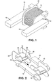
- Figure 1 shows a U-shaped yoke 10 of an electromechanical actuator or a relay, whose base portion 16, arranged between two limbs 12, 14 of the yoke 10, simultaneously forms a coil core for a coil 18 disposed thereon.
- the coil 18 is wound on a coil former 20 which has been slipped or pushed onto the base portion 16.
- the illustration shows that the coil former 20 with the coil 18 wound thereon cannot be pushed onto the base portion 16 in the ready-wound state because of the yoke limbs 12 and 14 bent in each case by 90 degrees to the base portion 16.
- a coil former 20 may be fitted onto the base 16 of the yoke 10.
- the coil former 20 comprises an opening 22 in its circumference, which opening 22 corresponds to the external circumference of the base portion 16 of the yoke 10.
- the coil former 20 consists in the variant shown of a U-shaped bobbin holder 24, the width of which corresponds to the width of the base portion 16 of the yoke 10.
- the bobbin holder 24 is flanked on both sides of its U-shaped profile by disk-shaped delimiting elements 26, 28, which are advantageously so dimensioned that they project beyond a fully-wound coil 18 at all points.
- the delimiting elements 26, 28 are in each case arranged perpendicularly to the surface of the bobbin holder 24 and finish in each case flush with the inside surface of the bobbin holder 24, such that the bobbin holder 24 may rest with its inside flat against three sides of the base portion 16 in the assembled state.
- the delimiting elements 26, 28 each comprise a bevel at their edges associated with the opening 22, so that the coil former 20 may be easily pushed onto the yoke.
- Catch lugs 30 are formed on the delimiting elements 26, 28 adjacent the opening 22, extending partially over the opening 22. Because of the narrowing opening, the U-shaped bobbin holder 24 is bent apart when being pushed onto the yoke 10. As soon as the coil former 20 has been pushed on completely, it snaps back into its starting position and it is held in its intended place on the base portion 16 by the catch lugs 30, functioning as fixing means. Once the coil former 20 has been pushed on in this way, the coil 18 may be wound thereon.
- FIG 3 shows an exploded view of a two-piece coil former 20, whose two coil former halves 32 and 34 may be latched together.
- the coil former 20 is divided horizontally, with each half comprising half of a bobbin holder 24 and half of each of two delimiting element 26, 28.
- Each of the two coil former halves 32, 34 comprises two catch lugs 36 arranged next to one another, which correspond in each case to corresponding catch lugs 38 on the other coil former half, such that the two coil former halves 32, 34 may latch together without play when the coil former is pushed onto the base portion 16 (c.f. Figure 4).
- the two catch connections are in each case arranged at the facing parting edges 40 of the two lateral delimiting elements 26 of the coil former 20.
- Each coil former half 32, 34 comprises in each case two catch lugs 36 on one side and two catch hooks 38 on the other side of the delimiting elements 26.
- the two coil former halves 32, 34 are so configured as to be interchangeable.
- FIGs 5 to 7 yet another embodiment of the invention, in which the two coil former halves 32 and 34 are connected together by means of two film hinges 42, such that the coil former 20 may be fitted by one coil former half 32 to the base portion 16 of the yoke 10 ( Figure 6), whereupon the other coil former half 34 may be swivelled through 180 degrees and latched to the first coil former half 32 ( Figure 7).
- a catch lug 36 and a corresponding catch hook 38 is provided in each case, such that the two coil former halves 32 and 34 may be latched together without play.
- the two film hinges 42 are in each case located at one end of the parting edges 40 of the delimiting elements 26 resting against one another in the closed state, which elements may be bulkier on the hinge side to provide better stability (c.f. Figure 6).
Landscapes
- Engineering & Computer Science (AREA)
- Power Engineering (AREA)
- Physics & Mathematics (AREA)
- Electromagnetism (AREA)
- Electromagnets (AREA)
- Insulation, Fastening Of Motor, Generator Windings (AREA)
Applications Claiming Priority (2)
| Application Number | Priority Date | Filing Date | Title |
|---|---|---|---|
| DE102004006712 | 2004-02-11 | ||
| DE102004006712A DE102004006712B4 (de) | 2004-02-11 | 2004-02-11 | Spulenkörper für einen elektromechanischen Aktor |
Publications (2)
| Publication Number | Publication Date |
|---|---|
| EP1564759A2 true EP1564759A2 (fr) | 2005-08-17 |
| EP1564759A3 EP1564759A3 (fr) | 2007-03-28 |
Family
ID=34684002
Family Applications (1)
| Application Number | Title | Priority Date | Filing Date |
|---|---|---|---|
| EP05002234A Ceased EP1564759A3 (fr) | 2004-02-11 | 2005-02-03 | Corps de bobine pour actionneur électromécanique |
Country Status (5)
| Country | Link |
|---|---|
| US (1) | US7180398B2 (fr) |
| EP (1) | EP1564759A3 (fr) |
| JP (1) | JP2005229114A (fr) |
| KR (1) | KR101065537B1 (fr) |
| DE (1) | DE102004006712B4 (fr) |
Families Citing this family (10)
| Publication number | Priority date | Publication date | Assignee | Title |
|---|---|---|---|---|
| KR101240854B1 (ko) * | 2011-11-11 | 2013-03-11 | 삼성전기주식회사 | 트랜스포머 |
| CN102737915B (zh) * | 2012-06-27 | 2015-01-28 | 宁波天波港联电子有限公司 | 衔铁安装结构 |
| TWI438794B (zh) * | 2013-03-13 | 2014-05-21 | Yujing Technology Co Ltd | The improved structure of the transformer |
| TWI493578B (zh) * | 2013-03-13 | 2015-07-21 | Yujing Technology Co Ltd | The improved structure of the wire frame |
| CN104143417B (zh) * | 2013-05-07 | 2016-12-28 | 明纬(广州)电子有限公司 | 一种变压器 |
| US9422766B2 (en) | 2013-07-17 | 2016-08-23 | Hunter Douglas, Inc. | Handle and brake arrangement for a covering for architectural openings |
| US9677330B2 (en) * | 2013-07-17 | 2017-06-13 | Hunter Douglas Inc. | Arrangement for a component housing for use in a rail of a window covering |
| US9708850B2 (en) * | 2013-07-17 | 2017-07-18 | Hunter Douglas Inc. | Arrangement for mounting an actuator button onto a rail of a window covering |
| KR20160099208A (ko) * | 2015-02-12 | 2016-08-22 | 엘지이노텍 주식회사 | 코일 부품, 이를 포함하는 대전류 인덕터 및 대전류 리액터 |
| DE102018010048A1 (de) | 2018-04-09 | 2019-10-10 | Wolfgang Mühlhaus | unabhängige Feldsteuerung |
Citations (1)
| Publication number | Priority date | Publication date | Assignee | Title |
|---|---|---|---|---|
| DE3638152A1 (de) * | 1986-11-08 | 1988-05-11 | Vogt Electronic Ag | Sensor fuer die messung der bremsbelagabnutzung an trommelbremsen |
Family Cites Families (21)
| Publication number | Priority date | Publication date | Assignee | Title |
|---|---|---|---|---|
| GB963874A (en) * | 1963-06-08 | 1964-07-15 | William Frederick Stahl | Coil former |
| DE1904579U (de) * | 1964-04-09 | 1964-11-19 | Siemens Ag | Spulenkoerper fuer ring- oder rahmenkernspulen. |
| JPS5142045Y1 (fr) * | 1967-12-22 | 1976-10-13 | ||
| AT280588B (de) | 1968-02-08 | 1970-04-27 | Vianova Kunstharz Ag | Verfahren zur Herstellung hitzehärtbarer Copolymerisate |
| DE2430034A1 (de) * | 1974-06-22 | 1976-01-08 | Hartmann & Braun Ag | Verfahren zur herstellung eines elektromagneten und danach hergestellter magnet |
| JPS5859339U (ja) * | 1981-10-16 | 1983-04-21 | 株式会社ニフコ | 発電機のコイルボビン |
| DE3273162D1 (en) * | 1982-06-19 | 1986-10-16 | Square D Starkstrom Gmbh | Coil bobbin for electric devices |
| DE8416629U1 (de) * | 1984-05-30 | 1984-08-23 | Weiner, Norbert, Dipl.-Ing., 5275 Bergneustadt | Spulenkoerper aus elastischem material |
| JPH0217452Y2 (fr) * | 1984-10-30 | 1990-05-16 | ||
| JPH06105665B2 (ja) * | 1986-03-31 | 1994-12-21 | 松下電器産業株式会社 | コイル部品の製造方法 |
| JPH0333045Y2 (fr) * | 1987-08-31 | 1991-07-12 | ||
| JP3182144B2 (ja) * | 1989-10-18 | 2001-07-03 | 松下電工株式会社 | 照明器具 |
| JPH0810940Y2 (ja) * | 1990-04-12 | 1996-03-29 | ティーディーケイ株式会社 | 小型プランジャのボビンとヨークの結合構造 |
| JPH0420206U (fr) * | 1990-06-08 | 1992-02-20 | ||
| JPH0629105U (ja) * | 1992-09-14 | 1994-04-15 | 株式会社トーキン | 小型ソレノイド |
| WO1996014643A1 (fr) * | 1994-11-04 | 1996-05-17 | Matsushita Electric Industrial Co., Ltd. | Filtre de ligne |
| KR200142307Y1 (ko) * | 1996-08-20 | 1999-06-01 | 왕중일 | 편향 요크용 보정 코일 |
| US5819397A (en) * | 1996-09-10 | 1998-10-13 | Square D Company | Method for assembling a three-phase current transformer |
| JP2001291614A (ja) * | 2000-04-11 | 2001-10-19 | Fuji Photo Film Co Ltd | カメラ用ソレノイド構造 |
| JP2001355559A (ja) | 2000-06-16 | 2001-12-26 | Shindengen Electric Mfg Co Ltd | イグニッションコイル |
| JP2002083711A (ja) | 2000-09-07 | 2002-03-22 | Olympus Optical Co Ltd | 電磁駆動装置 |
-
2004
- 2004-02-11 DE DE102004006712A patent/DE102004006712B4/de not_active Expired - Fee Related
-
2005
- 2005-02-03 EP EP05002234A patent/EP1564759A3/fr not_active Ceased
- 2005-02-04 KR KR1020050010362A patent/KR101065537B1/ko not_active Expired - Fee Related
- 2005-02-07 JP JP2005030332A patent/JP2005229114A/ja active Pending
- 2005-02-11 US US11/056,015 patent/US7180398B2/en not_active Expired - Fee Related
Patent Citations (1)
| Publication number | Priority date | Publication date | Assignee | Title |
|---|---|---|---|---|
| DE3638152A1 (de) * | 1986-11-08 | 1988-05-11 | Vogt Electronic Ag | Sensor fuer die messung der bremsbelagabnutzung an trommelbremsen |
Also Published As
| Publication number | Publication date |
|---|---|
| DE102004006712A1 (de) | 2005-09-08 |
| KR101065537B1 (ko) | 2011-09-19 |
| US7180398B2 (en) | 2007-02-20 |
| EP1564759A3 (fr) | 2007-03-28 |
| JP2005229114A (ja) | 2005-08-25 |
| US20050190034A1 (en) | 2005-09-01 |
| DE102004006712B4 (de) | 2006-08-31 |
| KR20060041691A (ko) | 2006-05-12 |
Similar Documents
| Publication | Publication Date | Title |
|---|---|---|
| EP1564759A2 (fr) | Corps de bobine pour actionneur électromécanique | |
| JP6403048B2 (ja) | 接点装置 | |
| US20040183313A1 (en) | Display case with magnetic latch assembly | |
| CN103311053B (zh) | 电磁继电器 | |
| JP2004335399A (ja) | 電磁継電器 | |
| JP6406596B2 (ja) | 接点装置 | |
| US20110017000A1 (en) | Slide apparatus for mobile communication terminal | |
| WO2015177962A1 (fr) | Contacteur électromagnétique | |
| EP1903580B1 (fr) | Actionneur à solénoïde | |
| JPH0412577B2 (fr) | ||
| KR0129533B1 (ko) | 케이지에 의해 보유되는 영구 자석을 갖는 전자석 | |
| CN102341541B (zh) | 无螺丝接合的连接部件 | |
| JP7666680B2 (ja) | コイル用コア | |
| JP4181191B2 (ja) | 電磁ソレノイド | |
| JPS5919378Y2 (ja) | 有極電磁石ブロツク | |
| JP2005050655A (ja) | 電磁リレー | |
| JPS5812414Y2 (ja) | 電磁石装置 | |
| CN2911900Y (zh) | 线性滤波器 | |
| CN101558548A (zh) | 绕线管、致动器及照相机用叶片驱动装置 | |
| JP2001291612A (ja) | ソレノイド | |
| JP3542933B2 (ja) | ラッチングソレノイド | |
| JP4026912B2 (ja) | 電磁継電器 | |
| JP2007027156A (ja) | 電磁ソレノイド | |
| JPH11274744A (ja) | 電装品の支持装置 | |
| JP2011050219A (ja) | モータ用ブラシ保持装置 |
Legal Events
| Date | Code | Title | Description |
|---|---|---|---|
| PUAI | Public reference made under article 153(3) epc to a published international application that has entered the european phase |
Free format text: ORIGINAL CODE: 0009012 |
|
| AK | Designated contracting states |
Kind code of ref document: A2 Designated state(s): AT BE BG CH CY CZ DE DK EE ES FI FR GB GR HU IE IS IT LI LT LU MC NL PL PT RO SE SI SK TR |
|
| AX | Request for extension of the european patent |
Extension state: AL BA HR LV MK YU |
|
| PUAL | Search report despatched |
Free format text: ORIGINAL CODE: 0009013 |
|
| AK | Designated contracting states |
Kind code of ref document: A3 Designated state(s): AT BE BG CH CY CZ DE DK EE ES FI FR GB GR HU IE IS IT LI LT LU MC NL PL PT RO SE SI SK TR |
|
| AX | Request for extension of the european patent |
Extension state: AL BA HR LV MK YU |
|
| 17P | Request for examination filed |
Effective date: 20070608 |
|
| AKX | Designation fees paid |
Designated state(s): AT BE BG CH CY CZ DE DK EE ES FI FR GB GR HU IE IS IT LI LT LU MC NL PL PT RO SE SI SK TR |
|
| 17Q | First examination report despatched |
Effective date: 20080509 |
|
| STAA | Information on the status of an ep patent application or granted ep patent |
Free format text: STATUS: THE APPLICATION HAS BEEN REFUSED |
|
| 18R | Application refused |
Effective date: 20111127 |