EP1568452A1 - Procédé de sciage des pièces en bois - Google Patents
Procédé de sciage des pièces en bois Download PDFInfo
- Publication number
- EP1568452A1 EP1568452A1 EP20050002753 EP05002753A EP1568452A1 EP 1568452 A1 EP1568452 A1 EP 1568452A1 EP 20050002753 EP20050002753 EP 20050002753 EP 05002753 A EP05002753 A EP 05002753A EP 1568452 A1 EP1568452 A1 EP 1568452A1
- Authority
- EP
- European Patent Office
- Prior art keywords
- woods
- station
- sawing
- wood
- sawing station
- Prior art date
- Legal status (The legal status is an assumption and is not a legal conclusion. Google has not performed a legal analysis and makes no representation as to the accuracy of the status listed.)
- Ceased
Links
- 238000000034 method Methods 0.000 title claims description 26
- 239000002023 wood Substances 0.000 claims abstract description 45
- 230000001105 regulatory effect Effects 0.000 claims description 6
- 238000012546 transfer Methods 0.000 description 10
- 238000012545 processing Methods 0.000 description 5
- 230000001276 controlling effect Effects 0.000 description 1
- 238000012937 correction Methods 0.000 description 1
- 238000005259 measurement Methods 0.000 description 1
- 238000004513 sizing Methods 0.000 description 1
- 239000007787 solid Substances 0.000 description 1
Images

Classifications
-
- B—PERFORMING OPERATIONS; TRANSPORTING
- B27—WORKING OR PRESERVING WOOD OR SIMILAR MATERIAL; NAILING OR STAPLING MACHINES IN GENERAL
- B27B—SAWS FOR WOOD OR SIMILAR MATERIAL; COMPONENTS OR ACCESSORIES THEREFOR
- B27B1/00—Methods for subdividing trunks or logs essentially involving sawing
- B27B1/007—Methods for subdividing trunks or logs essentially involving sawing taking into account geometric properties of the trunks or logs to be sawn, e.g. curvature
-
- B—PERFORMING OPERATIONS; TRANSPORTING
- B23—MACHINE TOOLS; METAL-WORKING NOT OTHERWISE PROVIDED FOR
- B23D—PLANING; SLOTTING; SHEARING; BROACHING; SAWING; FILING; SCRAPING; LIKE OPERATIONS FOR WORKING METAL BY REMOVING MATERIAL, NOT OTHERWISE PROVIDED FOR
- B23D47/00—Sawing machines or sawing devices working with circular saw blades, characterised only by constructional features of particular parts
- B23D47/04—Sawing machines or sawing devices working with circular saw blades, characterised only by constructional features of particular parts of devices for feeding, positioning, clamping, or rotating work
- B23D47/042—Sawing machines or sawing devices working with circular saw blades, characterised only by constructional features of particular parts of devices for feeding, positioning, clamping, or rotating work for conveying work to, or discharging work from, the machine
-
- B—PERFORMING OPERATIONS; TRANSPORTING
- B23—MACHINE TOOLS; METAL-WORKING NOT OTHERWISE PROVIDED FOR
- B23D—PLANING; SLOTTING; SHEARING; BROACHING; SAWING; FILING; SCRAPING; LIKE OPERATIONS FOR WORKING METAL BY REMOVING MATERIAL, NOT OTHERWISE PROVIDED FOR
- B23D59/00—Accessories specially designed for sawing machines or sawing devices
- B23D59/001—Measuring or control devices, e.g. for automatic control of work feed pressure on band saw blade
- B23D59/002—Measuring or control devices, e.g. for automatic control of work feed pressure on band saw blade for the position of the saw blade
-
- B—PERFORMING OPERATIONS; TRANSPORTING
- B27—WORKING OR PRESERVING WOOD OR SIMILAR MATERIAL; NAILING OR STAPLING MACHINES IN GENERAL
- B27B—SAWS FOR WOOD OR SIMILAR MATERIAL; COMPONENTS OR ACCESSORIES THEREFOR
- B27B1/00—Methods for subdividing trunks or logs essentially involving sawing
- B27B1/002—Methods for subdividing trunks or logs essentially involving sawing by cross-cutting
-
- B—PERFORMING OPERATIONS; TRANSPORTING
- B27—WORKING OR PRESERVING WOOD OR SIMILAR MATERIAL; NAILING OR STAPLING MACHINES IN GENERAL
- B27B—SAWS FOR WOOD OR SIMILAR MATERIAL; COMPONENTS OR ACCESSORIES THEREFOR
- B27B31/00—Arrangements for conveying, loading, turning, adjusting, or discharging the log or timber, specially designed for saw mills or sawing machines
-
- Y—GENERAL TAGGING OF NEW TECHNOLOGICAL DEVELOPMENTS; GENERAL TAGGING OF CROSS-SECTIONAL TECHNOLOGIES SPANNING OVER SEVERAL SECTIONS OF THE IPC; TECHNICAL SUBJECTS COVERED BY FORMER USPC CROSS-REFERENCE ART COLLECTIONS [XRACs] AND DIGESTS
- Y10—TECHNICAL SUBJECTS COVERED BY FORMER USPC
- Y10T—TECHNICAL SUBJECTS COVERED BY FORMER US CLASSIFICATION
- Y10T83/00—Cutting
- Y10T83/04—Processes
-
- Y—GENERAL TAGGING OF NEW TECHNOLOGICAL DEVELOPMENTS; GENERAL TAGGING OF CROSS-SECTIONAL TECHNOLOGIES SPANNING OVER SEVERAL SECTIONS OF THE IPC; TECHNICAL SUBJECTS COVERED BY FORMER USPC CROSS-REFERENCE ART COLLECTIONS [XRACs] AND DIGESTS
- Y10—TECHNICAL SUBJECTS COVERED BY FORMER USPC
- Y10T—TECHNICAL SUBJECTS COVERED BY FORMER US CLASSIFICATION
- Y10T83/00—Cutting
- Y10T83/647—With means to convey work relative to tool station
- Y10T83/6475—With means to regulate work-feed speed
Definitions
- the invention relates to a method for sawing wood after the preamble of claim 1.
- the invention is based on the object, the generic method form so that the processing of the timbers in the time unit optimal.
- the respective subsequent Wood also fed towards the sawing station when in there the previous wood is still being processed.
- the feeding speed the respective subsequent wood is preferably chosen so that it enters the sawing station, if the previous wood just leaving the sawing station.
- the feed rate becomes set so that the subsequent wood on the one hand not on the wood in the sawing station accumulates, on the other hand, the distance between these woods is minimal. This can be done in the time unit a very high number of woods are processed.
- the feed rate of the woods in the Saw station is regulated.
- the feeding speed of the subsequent wood are optimally controlled by the controller.
- the woods are advantageous before processing in the sawing station measured in their length and / or in terms of their quality.
- the measured values are expediently stored, advantageously in a computer of a controller.
- the feed rate of the Woods are optimally regulated to the sawing station, so that the distance the woods in the sawing station can be minimized.
- the Saw station fed wood advantageous without interruption transported.
- the drive for transporting the following woods decoupled from the drive of the woods in the sawing station is continuous, possibly also with variable speed.
- the wood to be sawn 1 by means of a transport device fed in the direction of arrow 2 a polegestation 3. She has a chop saw 4, with the woods 1 across, preferably perpendicular to their Transport direction 2 are cut to length.
- the chop saw 4 is this with a saw blade 5 provided in a corresponding guide in Height direction is moved during the sawing process.
- the woods 1 are first passed past a measuring station 6, at the timber measured 1 at least in terms of their length become. Because the woods have different qualities and / or too Having errors, these are usually marked manually, for example with chalk marks. Basically, it is also possible to Quality, any errors and also the length of the woods 1 by means of a Automatically detect scanners. As this is known, will this is not explained in detail.
- the data thus acquired are in one Calculator stored in a so-called cut list, based on the in sawing station 3 sawed the respective timber 1 to the necessary extent becomes.
- the woods 1 are the measuring station 6 on a first transport device 7 supplied. It can be transported by transport chains, conveyor belts, Timing belt and the like may be formed.
- the measuring station 6 and the transfer station 8 have the same transport device 7. It has a controllable Drive, a servomotor or a frequency-controlled motor can be. With him it is possible to increase the transport speed in to be described depending on the sawing process in to control the shegestation 3.
- the measuring station 6 and the sawing station 3 in a line. Of course These two stations 3, 6 can not be in one Be arranged line.
- the woods 1 are by the sawing station 3 with a second Transport device 9 transported, which like the first transport device 7 a conveyor belt, a transport chain, a toothed belt, Rolls or the like can be.
- the transport device 9 has a second (not shown), the drive in conventional Way can be formed.
- the transfer station 8 is the area between the measuring station 6 and the saw station 3.
- the length of the transfer station 8 corresponds to at least the maximum length of the wood to be worked 1.
- the length of the transfer station 8 is a Multiple of the length of the woods 1.
- the distance between the measuring station 6 and the sawing station 3 need only be as large as the maximum Wood length. So that the performance of the chop saw is increased takes place the supply of the woods 1 to the sawing station 3 such that the next Wood 1 then enters the sawing station 3, if the previous one Wood 1 has just left the sawing station 3.
- the distance between successive woods 1 in the sawing station 3 is optimal chosen so that the subsequent timber 1 with its front side with a small distance the rear end of the previous Wood follows, without contact with the previous wood to get. After reaching a small gap both will Woods advantageously transported at the same speed.
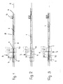
- Fig. 1 shows the Case that the wood 1 has just run into the sawing station 3, while the following wood 1 already in the transfer station 8 is located.
- the wood located in the sawing station 3 is correspondingly the previous sizing with the saw blade 5 in several Parts cut. This is the wood 1 after each cut transported by a corresponding amount.
- the transport device 7 is the following Wood 1 transported further in the transfer station 8 during the sawing process.
- Fig. 2 shows that the subsequent timber 1 only a small distance from the rear end 10 of the saw station 3 located timber 1 has. During the sawing process Thus, the respective subsequent timber 1 is advantageous without stopping fed to the sawing station 3.
- Fig. 3 shows the situation in which the rear end 10 of the last Part of the cut wood 1 is located behind the saw blade 5.
- the following wood 1 has already been transported to the sawing station has only minimal distance from the rear End 10 of the previous wood 1. Therefore, once the wood 1 the Saw station 3 has left, immediately after the next Sawed wood 1. Now while this wood 1 in the sawing station 3, is already in the described manner the next Wood 1 fed.
- the speed will be the tracked timber 1 adapted accordingly. Because the length as well as the errors and quality marks of the woods 1 in the im Calculator stored cut list, the scheme can be based on This cut list the transport speed of the transport device 7 set exactly so that the distances between successive Wood 1 in the sawing station 3 is reduced to a minimum become. Depending on the processing time in the sawing station 3 can the transport of the following woods 1 definitely interrupted become.
- the transport of the woods 1 through the measuring station 6 and the transfer station 8 takes place at different speeds, the be determined by an intelligent controller.
- the position of the Woods 1 in the measuring station 6, in the transfer station 8 as well as in The saw station 3 is tracked by Wegmeßsysteme, the two Capture ends of the respective timber 1.
- Fig. 4 shows schematically, the position of the woods 1 on the Transport device 7, for example by means of a light scanner 11th detected, the signals of the controller 12 are supplied.
- the signals of the controller 12 are supplied in the area the feed direction 9 in the sawing station 3 .
- the input signals of the two light sensors 11, 13 give the position of the transport devices or the woods 1 and the position of the saw. Based on the input signals is the Speed of the transport devices 7, 9 and the speed the saw set so that successive woods 1 have a minimum distance from each other.
- the measured values as well as the speed of the transport devices 7, 9 are fed to the computer or the controller. Based on these values, the controller continuously evaluates the positions of the Beginnings and ends of the woods 1 to each other.
- the required Feeding rate of each subsequent timber 1 is variable regulated, the feed rate is constantly new in the Control is calculated. In this case, in the manner described the detected and stored values for controlling the feed rate used. This allows the distance between successive woods 1 during their transport to the sawing station 3 be kept minimal.
Landscapes
- Life Sciences & Earth Sciences (AREA)
- Engineering & Computer Science (AREA)
- Mechanical Engineering (AREA)
- Wood Science & Technology (AREA)
- Forests & Forestry (AREA)
- Control Of Conveyors (AREA)
Applications Claiming Priority (2)
| Application Number | Priority Date | Filing Date | Title |
|---|---|---|---|
| DE200410010334 DE102004010334A1 (de) | 2004-02-24 | 2004-02-24 | Verfahren zum Sägen von Hölzern |
| DE102004010334 | 2004-02-24 |
Publications (1)
| Publication Number | Publication Date |
|---|---|
| EP1568452A1 true EP1568452A1 (fr) | 2005-08-31 |
Family
ID=34745357
Family Applications (1)
| Application Number | Title | Priority Date | Filing Date |
|---|---|---|---|
| EP20050002753 Ceased EP1568452A1 (fr) | 2004-02-24 | 2005-02-10 | Procédé de sciage des pièces en bois |
Country Status (5)
| Country | Link |
|---|---|
| US (1) | US20050183554A1 (fr) |
| EP (1) | EP1568452A1 (fr) |
| CN (1) | CN100532034C (fr) |
| DE (1) | DE102004010334A1 (fr) |
| TW (1) | TW200530003A (fr) |
Cited By (1)
| Publication number | Priority date | Publication date | Assignee | Title |
|---|---|---|---|---|
| EP1995191A1 (fr) * | 2007-05-25 | 2008-11-26 | Holtec GmbH & Co.KG | Dispositif d'alimentation de bois ronds |
Families Citing this family (6)
| Publication number | Priority date | Publication date | Assignee | Title |
|---|---|---|---|---|
| US20070028730A1 (en) * | 2003-08-20 | 2007-02-08 | Sawyer Philip P | Apparatus and methods for double ended processing |
| US20060219071A1 (en) * | 2005-04-01 | 2006-10-05 | Coe Newnes/Mcgehee Ulc | Method of optimizing processing of successive workpieces through cutting machines |
| CN102756407B (zh) * | 2011-04-28 | 2015-03-25 | 张仁文 | 板材尺寸测量及加工方法 |
| US20140290456A1 (en) * | 2013-03-15 | 2014-10-02 | Hasko, Inc. | Two-saw assembly high-speed production chop-saw |
| DE102014011689A1 (de) * | 2014-08-04 | 2016-02-04 | GreCon Dimter Holzoptimierung Süd GmbH & Co. KG | Vorrichtung und Verfahren zur Durchführung von Kappschnitten an Werkstücken aus Holz |
| FI128073B (fi) * | 2016-12-14 | 2019-09-13 | Veisto Oy | Menetelmä sahalinjan käyttämiseksi ja sahalinja |
Citations (3)
| Publication number | Priority date | Publication date | Assignee | Title |
|---|---|---|---|---|
| US6308603B1 (en) * | 1994-08-29 | 2001-10-30 | Robert J. Murray | Method and apparatus for bucksawing logs |
| US20020069937A1 (en) * | 1999-04-30 | 2002-06-13 | Murray Robert James | Method and apparatus for bucksawing logs |
| WO2002045925A1 (fr) * | 2000-12-07 | 2002-06-13 | Tähkä Oy | Appareil et procede pour la manutention de grumes |
Family Cites Families (16)
| Publication number | Priority date | Publication date | Assignee | Title |
|---|---|---|---|---|
| DE3314175C1 (de) * | 1983-04-19 | 1984-08-16 | Josef Aigner KG, 8223 Traunreut | Verfahren und Vorrichtung zum Ablängen von Holz |
| US4640160A (en) * | 1985-12-09 | 1987-02-03 | Brunette Machine Works, Ltd. | Sweep-data-responsive, high-speed, continuous-log-travel bucking apparatus |
| US4879752A (en) * | 1987-11-18 | 1989-11-07 | Macmillan Bloedel Limited | Lumber optimizer |
| US4887219A (en) * | 1988-02-02 | 1989-12-12 | Strauser Manufacturing, Inc. | Board cut-off saw assembly |
| US4907294A (en) * | 1988-04-28 | 1990-03-06 | U.S. Natural Resources, Inc. | Log scanning system |
| US4934228A (en) * | 1989-01-13 | 1990-06-19 | U.S. Natural Resources, Inc. | System for diverting veneer sheets having offsize defects |
| CN2143163Y (zh) * | 1992-10-24 | 1993-10-06 | 李宗伟 | 多片圆锯机 |
| DE4327040A1 (de) * | 1993-08-12 | 1995-02-16 | Wurster & Dietz Maschf | Fördereinrichtung für Holzerzeugnisse |
| US5884682A (en) * | 1996-03-21 | 1999-03-23 | Cae Newnes Ltd. | Position-based integrated motion controlled curve sawing |
| US5685410A (en) * | 1996-09-03 | 1997-11-11 | U.S. Natural Resources, Inc. | Infeed conveyor system |
| US6550605B1 (en) * | 1999-11-19 | 2003-04-22 | Firme Cogites Inc. | Apparatus and method for feeding elongated elements |
| CA2426378C (fr) * | 2003-04-30 | 2012-03-13 | Sawquip International Inc. | Appareil de positionnement et de transport de bille de bois |
| CA2469544C (fr) * | 2003-05-30 | 2009-03-24 | Darryl Irwin Kujat | Systeme d'entrainement a elevation pour transporteur |
| US20060037450A1 (en) * | 2004-08-17 | 2006-02-23 | Pobuda Ronald H | Flying saw and flighted chain conveyor apparatus |
| US7694614B2 (en) * | 2005-12-01 | 2010-04-13 | Walgreen, Co | Case cutter assembly |
| US7578382B2 (en) * | 2007-02-07 | 2009-08-25 | Cnm Acquisition Llc | Virtual lug loader |
-
2004
- 2004-02-24 DE DE200410010334 patent/DE102004010334A1/de not_active Withdrawn
- 2004-04-29 US US10/709,344 patent/US20050183554A1/en not_active Abandoned
- 2004-12-30 TW TW93141320A patent/TW200530003A/zh not_active IP Right Cessation
-
2005
- 2005-02-10 EP EP20050002753 patent/EP1568452A1/fr not_active Ceased
- 2005-02-18 CN CNB2005100093929A patent/CN100532034C/zh not_active Expired - Fee Related
Patent Citations (3)
| Publication number | Priority date | Publication date | Assignee | Title |
|---|---|---|---|---|
| US6308603B1 (en) * | 1994-08-29 | 2001-10-30 | Robert J. Murray | Method and apparatus for bucksawing logs |
| US20020069937A1 (en) * | 1999-04-30 | 2002-06-13 | Murray Robert James | Method and apparatus for bucksawing logs |
| WO2002045925A1 (fr) * | 2000-12-07 | 2002-06-13 | Tähkä Oy | Appareil et procede pour la manutention de grumes |
Cited By (1)
| Publication number | Priority date | Publication date | Assignee | Title |
|---|---|---|---|---|
| EP1995191A1 (fr) * | 2007-05-25 | 2008-11-26 | Holtec GmbH & Co.KG | Dispositif d'alimentation de bois ronds |
Also Published As
| Publication number | Publication date |
|---|---|
| TW200530003A (en) | 2005-09-16 |
| CN1660552A (zh) | 2005-08-31 |
| TWI352012B (fr) | 2011-11-11 |
| US20050183554A1 (en) | 2005-08-25 |
| DE102004010334A1 (de) | 2005-09-08 |
| CN100532034C (zh) | 2009-08-26 |
Similar Documents
| Publication | Publication Date | Title |
|---|---|---|
| DE3621357C1 (de) | Kappsaege zum Ablaengen von Brettern | |
| EP1990148B1 (fr) | Dispositif de transport de planches vers des scies à tronçonner | |
| DE2714973C2 (de) | Vorrichtung zum Vorschieben von Rohbrettern zu einer Kantenbesäumsäge | |
| DE3415932A1 (de) | Vorrichtung zur spanenden bearbeitung der seiten von holzstaemmen | |
| DE2434449B2 (de) | Verfahren und Vorrichtung zum Fördern von Filterstäben oder Zigaretten | |
| DE3632263C2 (fr) | ||
| EP1568452A1 (fr) | Procédé de sciage des pièces en bois | |
| EP0963822B1 (fr) | Dispositif et procédé pour le sciage des troncs d'arbres | |
| EP2982485B1 (fr) | Dispositif et procede d'execution de coupes transversales sur des pieces en bois | |
| EP0561227B1 (fr) | Machine-outil pour l'usinage de poutrelles ou similaires | |
| DE3914625C2 (fr) | ||
| DE202020104273U1 (de) | Sägeanlage zum Sägen eines Sägeguts | |
| DE102020103192B4 (de) | Sägeanlage und Verfahren zum Sägen eines Sägeguts | |
| CH658016A5 (de) | Holzbearbeitungsmaschine zum zapfenschlagen und laengsprofilieren von hoelzern, insbesondere von fensterhoelzern. | |
| DE3303162A1 (de) | Endprofiliermaschine | |
| AT511535B1 (de) | Sägevorrichtung zum sägen eines werkstückes | |
| EP1038643A2 (fr) | Ensemble de scies à ruban pour la découpe de troncs d'arbres, en particulier des quarts d'arbres | |
| DE2054831A1 (de) | Vorrichtung zur automatischen Übergabe von Holzwerkstücken | |
| DE3820148C2 (fr) | ||
| DE2940820A1 (de) | Blockbandsaege | |
| DE2928086C2 (de) | Verfahren und Vorrichtung zum Besäumen von baumkantigen Brettern | |
| DE19513610C2 (de) | Verfahren und Vorrichtung zur Förderung von Werkstücken | |
| EP0812666A2 (fr) | Procédé pour le contrÔle des coupes transversales et scie pour sa mise en oeuvre | |
| DE19828238C2 (de) | Vorrichtung und Verfahren zum Zerteilen von Baumstämmen | |
| AT395691B (de) | Vorrichtung zum bearbeiten rohr- oder stangenfoermiger werkstuecke |
Legal Events
| Date | Code | Title | Description |
|---|---|---|---|
| PUAI | Public reference made under article 153(3) epc to a published international application that has entered the european phase |
Free format text: ORIGINAL CODE: 0009012 |
|
| AK | Designated contracting states |
Kind code of ref document: A1 Designated state(s): AT BE BG CH CY CZ DE DK EE ES FI FR GB GR HU IE IS IT LI LT LU MC NL PL PT RO SE SI SK TR |
|
| AX | Request for extension of the european patent |
Extension state: AL BA HR LV MK YU |
|
| 17P | Request for examination filed |
Effective date: 20060221 |
|
| AKX | Designation fees paid |
Designated state(s): AT BE BG CH CY CZ DE DK EE ES FI FR GB GR HU IE IS IT LI LT LU MC NL PL PT RO SE SI SK TR |
|
| APBK | Appeal reference recorded |
Free format text: ORIGINAL CODE: EPIDOSNREFNE |
|
| APBN | Date of receipt of notice of appeal recorded |
Free format text: ORIGINAL CODE: EPIDOSNNOA2E |
|
| APBR | Date of receipt of statement of grounds of appeal recorded |
Free format text: ORIGINAL CODE: EPIDOSNNOA3E |
|
| APAF | Appeal reference modified |
Free format text: ORIGINAL CODE: EPIDOSCREFNE |
|
| APBT | Appeal procedure closed |
Free format text: ORIGINAL CODE: EPIDOSNNOA9E |
|
| STAA | Information on the status of an ep patent application or granted ep patent |
Free format text: STATUS: THE APPLICATION HAS BEEN REFUSED |
|
| 18R | Application refused |
Effective date: 20140911 |