EP1569251B1 - Versiegelter Seltenerdmagnet und Verfahren zu seiner Herstellung - Google Patents
Versiegelter Seltenerdmagnet und Verfahren zu seiner Herstellung Download PDFInfo
- Publication number
- EP1569251B1 EP1569251B1 EP05251041.9A EP05251041A EP1569251B1 EP 1569251 B1 EP1569251 B1 EP 1569251B1 EP 05251041 A EP05251041 A EP 05251041A EP 1569251 B1 EP1569251 B1 EP 1569251B1
- Authority
- EP
- European Patent Office
- Prior art keywords
- rare earth
- magnet
- earth magnet
- case
- sealed
- Prior art date
- Legal status (The legal status is an assumption and is not a legal conclusion. Google has not performed a legal analysis and makes no representation as to the accuracy of the status listed.)
- Ceased
Links
- 229910052761 rare earth metal Inorganic materials 0.000 title claims description 88
- 150000002910 rare earth metals Chemical class 0.000 title claims description 86
- 238000004519 manufacturing process Methods 0.000 title claims description 23
- 238000000034 method Methods 0.000 title claims description 23
- 229910052782 aluminium Inorganic materials 0.000 claims description 33
- XAGFODPZIPBFFR-UHFFFAOYSA-N aluminium Chemical compound [Al] XAGFODPZIPBFFR-UHFFFAOYSA-N 0.000 claims description 33
- UFHFLCQGNIYNRP-UHFFFAOYSA-N Hydrogen Chemical compound [H][H] UFHFLCQGNIYNRP-UHFFFAOYSA-N 0.000 claims description 32
- 239000000463 material Substances 0.000 claims description 12
- 238000007789 sealing Methods 0.000 claims description 12
- 229910000838 Al alloy Inorganic materials 0.000 claims description 10
- 230000035515 penetration Effects 0.000 claims description 5
- 238000002844 melting Methods 0.000 claims description 4
- 230000008018 melting Effects 0.000 claims description 4
- QVGXLLKOCUKJST-UHFFFAOYSA-N atomic oxygen Chemical compound [O] QVGXLLKOCUKJST-UHFFFAOYSA-N 0.000 claims description 2
- 238000005304 joining Methods 0.000 claims description 2
- 238000003754 machining Methods 0.000 claims description 2
- 239000000696 magnetic material Substances 0.000 claims description 2
- 239000001301 oxygen Substances 0.000 claims description 2
- 229910052760 oxygen Inorganic materials 0.000 claims description 2
- 239000004411 aluminium Substances 0.000 claims 1
- 230000000052 comparative effect Effects 0.000 description 17
- 239000001257 hydrogen Substances 0.000 description 17
- 229910052739 hydrogen Inorganic materials 0.000 description 17
- XEEYBQQBJWHFJM-UHFFFAOYSA-N iron Substances [Fe] XEEYBQQBJWHFJM-UHFFFAOYSA-N 0.000 description 13
- PXHVJJICTQNCMI-UHFFFAOYSA-N Nickel Chemical compound [Ni] PXHVJJICTQNCMI-UHFFFAOYSA-N 0.000 description 11
- 239000004065 semiconductor Substances 0.000 description 11
- 238000006243 chemical reaction Methods 0.000 description 8
- 229910052802 copper Inorganic materials 0.000 description 7
- 239000010949 copper Substances 0.000 description 7
- 238000007747 plating Methods 0.000 description 7
- 238000004381 surface treatment Methods 0.000 description 7
- 229910052759 nickel Inorganic materials 0.000 description 6
- RYGMFSIKBFXOCR-UHFFFAOYSA-N Copper Chemical compound [Cu] RYGMFSIKBFXOCR-UHFFFAOYSA-N 0.000 description 5
- 229910045601 alloy Inorganic materials 0.000 description 5
- 239000000956 alloy Substances 0.000 description 5
- 230000005415 magnetization Effects 0.000 description 5
- 239000000654 additive Substances 0.000 description 4
- 230000032683 aging Effects 0.000 description 4
- 239000007789 gas Substances 0.000 description 4
- 229910052742 iron Inorganic materials 0.000 description 4
- 239000000843 powder Substances 0.000 description 4
- 238000011109 contamination Methods 0.000 description 3
- 238000010438 heat treatment Methods 0.000 description 3
- 239000000203 mixture Substances 0.000 description 3
- 229910018131 Al-Mn Inorganic materials 0.000 description 2
- 229910018464 Al—Mg—Si Inorganic materials 0.000 description 2
- 229910018461 Al—Mn Inorganic materials 0.000 description 2
- XKRFYHLGVUSROY-UHFFFAOYSA-N Argon Chemical compound [Ar] XKRFYHLGVUSROY-UHFFFAOYSA-N 0.000 description 2
- 229910052684 Cerium Inorganic materials 0.000 description 2
- 229910052692 Dysprosium Inorganic materials 0.000 description 2
- 229910052691 Erbium Inorganic materials 0.000 description 2
- 229910052693 Europium Inorganic materials 0.000 description 2
- 229910052688 Gadolinium Inorganic materials 0.000 description 2
- 229910052689 Holmium Inorganic materials 0.000 description 2
- 229910052765 Lutetium Inorganic materials 0.000 description 2
- 229910052779 Neodymium Inorganic materials 0.000 description 2
- 229910052777 Praseodymium Inorganic materials 0.000 description 2
- 229910052772 Samarium Inorganic materials 0.000 description 2
- 229910052771 Terbium Inorganic materials 0.000 description 2
- 229910052775 Thulium Inorganic materials 0.000 description 2
- 229910052769 Ytterbium Inorganic materials 0.000 description 2
- 230000005856 abnormality Effects 0.000 description 2
- 229910052796 boron Inorganic materials 0.000 description 2
- 238000009694 cold isostatic pressing Methods 0.000 description 2
- 238000005260 corrosion Methods 0.000 description 2
- 230000007797 corrosion Effects 0.000 description 2
- 238000001514 detection method Methods 0.000 description 2
- 230000000694 effects Effects 0.000 description 2
- 229910052746 lanthanum Inorganic materials 0.000 description 2
- 229910052751 metal Inorganic materials 0.000 description 2
- 239000002184 metal Substances 0.000 description 2
- 239000002245 particle Substances 0.000 description 2
- 238000003825 pressing Methods 0.000 description 2
- 239000002994 raw material Substances 0.000 description 2
- 238000003466 welding Methods 0.000 description 2
- 229910052727 yttrium Inorganic materials 0.000 description 2
- 229910052726 zirconium Inorganic materials 0.000 description 2
- 229910018134 Al-Mg Inorganic materials 0.000 description 1
- 229910018125 Al-Si Inorganic materials 0.000 description 1
- 229910018137 Al-Zn Inorganic materials 0.000 description 1
- 229910018182 Al—Cu Inorganic materials 0.000 description 1
- 229910018467 Al—Mg Inorganic materials 0.000 description 1
- 229910018520 Al—Si Inorganic materials 0.000 description 1
- 229910018573 Al—Zn Inorganic materials 0.000 description 1
- ZOXJGFHDIHLPTG-UHFFFAOYSA-N Boron Chemical compound [B] ZOXJGFHDIHLPTG-UHFFFAOYSA-N 0.000 description 1
- 229910000831 Steel Inorganic materials 0.000 description 1
- 230000002159 abnormal effect Effects 0.000 description 1
- 238000005299 abrasion Methods 0.000 description 1
- 230000000996 additive effect Effects 0.000 description 1
- 230000003064 anti-oxidating effect Effects 0.000 description 1
- 229910052786 argon Inorganic materials 0.000 description 1
- 230000015556 catabolic process Effects 0.000 description 1
- GWXLDORMOJMVQZ-UHFFFAOYSA-N cerium Chemical compound [Ce] GWXLDORMOJMVQZ-UHFFFAOYSA-N 0.000 description 1
- 229910052804 chromium Inorganic materials 0.000 description 1
- 239000011248 coating agent Substances 0.000 description 1
- 238000000576 coating method Methods 0.000 description 1
- 238000004040 coloring Methods 0.000 description 1
- 238000001816 cooling Methods 0.000 description 1
- 238000006731 degradation reaction Methods 0.000 description 1
- 230000000593 degrading effect Effects 0.000 description 1
- 238000005238 degreasing Methods 0.000 description 1
- 238000001035 drying Methods 0.000 description 1
- KBQHZAAAGSGFKK-UHFFFAOYSA-N dysprosium atom Chemical compound [Dy] KBQHZAAAGSGFKK-UHFFFAOYSA-N 0.000 description 1
- 238000005516 engineering process Methods 0.000 description 1
- UYAHIZSMUZPPFV-UHFFFAOYSA-N erbium Chemical compound [Er] UYAHIZSMUZPPFV-UHFFFAOYSA-N 0.000 description 1
- 238000005530 etching Methods 0.000 description 1
- OGPBJKLSAFTDLK-UHFFFAOYSA-N europium atom Chemical compound [Eu] OGPBJKLSAFTDLK-UHFFFAOYSA-N 0.000 description 1
- 239000000446 fuel Substances 0.000 description 1
- UIWYJDYFSGRHKR-UHFFFAOYSA-N gadolinium atom Chemical compound [Gd] UIWYJDYFSGRHKR-UHFFFAOYSA-N 0.000 description 1
- 229910052733 gallium Inorganic materials 0.000 description 1
- 229910052735 hafnium Inorganic materials 0.000 description 1
- KJZYNXUDTRRSPN-UHFFFAOYSA-N holmium atom Chemical compound [Ho] KJZYNXUDTRRSPN-UHFFFAOYSA-N 0.000 description 1
- 238000001513 hot isostatic pressing Methods 0.000 description 1
- 238000010191 image analysis Methods 0.000 description 1
- 238000007733 ion plating Methods 0.000 description 1
- 229910052747 lanthanoid Inorganic materials 0.000 description 1
- 150000002602 lanthanoids Chemical class 0.000 description 1
- FZLIPJUXYLNCLC-UHFFFAOYSA-N lanthanum atom Chemical compound [La] FZLIPJUXYLNCLC-UHFFFAOYSA-N 0.000 description 1
- OHSVLFRHMCKCQY-UHFFFAOYSA-N lutetium atom Chemical compound [Lu] OHSVLFRHMCKCQY-UHFFFAOYSA-N 0.000 description 1
- 229910052748 manganese Inorganic materials 0.000 description 1
- 239000007769 metal material Substances 0.000 description 1
- 229910052750 molybdenum Inorganic materials 0.000 description 1
- QEFYFXOXNSNQGX-UHFFFAOYSA-N neodymium atom Chemical compound [Nd] QEFYFXOXNSNQGX-UHFFFAOYSA-N 0.000 description 1
- 229910001172 neodymium magnet Inorganic materials 0.000 description 1
- 230000003472 neutralizing effect Effects 0.000 description 1
- 229910052758 niobium Inorganic materials 0.000 description 1
- 230000003647 oxidation Effects 0.000 description 1
- 238000007254 oxidation reaction Methods 0.000 description 1
- PUDIUYLPXJFUGB-UHFFFAOYSA-N praseodymium atom Chemical compound [Pr] PUDIUYLPXJFUGB-UHFFFAOYSA-N 0.000 description 1
- 239000011347 resin Substances 0.000 description 1
- 229920005989 resin Polymers 0.000 description 1
- KZUNJOHGWZRPMI-UHFFFAOYSA-N samarium atom Chemical compound [Sm] KZUNJOHGWZRPMI-UHFFFAOYSA-N 0.000 description 1
- 229910052706 scandium Inorganic materials 0.000 description 1
- SIXSYDAISGFNSX-UHFFFAOYSA-N scandium atom Chemical compound [Sc] SIXSYDAISGFNSX-UHFFFAOYSA-N 0.000 description 1
- 229910052710 silicon Inorganic materials 0.000 description 1
- 229910052709 silver Inorganic materials 0.000 description 1
- 238000005245 sintering Methods 0.000 description 1
- 239000010959 steel Substances 0.000 description 1
- 238000003860 storage Methods 0.000 description 1
- 229910052715 tantalum Inorganic materials 0.000 description 1
- GZCRRIHWUXGPOV-UHFFFAOYSA-N terbium atom Chemical compound [Tb] GZCRRIHWUXGPOV-UHFFFAOYSA-N 0.000 description 1
- FRNOGLGSGLTDKL-UHFFFAOYSA-N thulium atom Chemical compound [Tm] FRNOGLGSGLTDKL-UHFFFAOYSA-N 0.000 description 1
- 229910052718 tin Inorganic materials 0.000 description 1
- 229910052719 titanium Inorganic materials 0.000 description 1
- 229910052721 tungsten Inorganic materials 0.000 description 1
- 229910052720 vanadium Inorganic materials 0.000 description 1
- 238000011179 visual inspection Methods 0.000 description 1
- XLYOFNOQVPJJNP-UHFFFAOYSA-N water Substances O XLYOFNOQVPJJNP-UHFFFAOYSA-N 0.000 description 1
- NAWDYIZEMPQZHO-UHFFFAOYSA-N ytterbium Chemical compound [Yb] NAWDYIZEMPQZHO-UHFFFAOYSA-N 0.000 description 1
- VWQVUPCCIRVNHF-UHFFFAOYSA-N yttrium atom Chemical compound [Y] VWQVUPCCIRVNHF-UHFFFAOYSA-N 0.000 description 1
- 229910052725 zinc Inorganic materials 0.000 description 1
- 239000011701 zinc Substances 0.000 description 1
Images

Classifications
-
- H—ELECTRICITY
- H01—ELECTRIC ELEMENTS
- H01F—MAGNETS; INDUCTANCES; TRANSFORMERS; SELECTION OF MATERIALS FOR THEIR MAGNETIC PROPERTIES
- H01F41/00—Apparatus or processes specially adapted for manufacturing or assembling magnets, inductances or transformers; Apparatus or processes specially adapted for manufacturing materials characterised by their magnetic properties
- H01F41/02—Apparatus or processes specially adapted for manufacturing or assembling magnets, inductances or transformers; Apparatus or processes specially adapted for manufacturing materials characterised by their magnetic properties for manufacturing cores, coils, or magnets
- H01F41/0253—Apparatus or processes specially adapted for manufacturing or assembling magnets, inductances or transformers; Apparatus or processes specially adapted for manufacturing materials characterised by their magnetic properties for manufacturing cores, coils, or magnets for manufacturing permanent magnets
- H01F41/026—Apparatus or processes specially adapted for manufacturing or assembling magnets, inductances or transformers; Apparatus or processes specially adapted for manufacturing materials characterised by their magnetic properties for manufacturing cores, coils, or magnets for manufacturing permanent magnets protecting methods against environmental influences, e.g. oxygen, by surface treatment
-
- H—ELECTRICITY
- H01—ELECTRIC ELEMENTS
- H01F—MAGNETS; INDUCTANCES; TRANSFORMERS; SELECTION OF MATERIALS FOR THEIR MAGNETIC PROPERTIES
- H01F7/00—Magnets
- H01F7/02—Permanent magnets [PM]
- H01F7/0205—Magnetic circuits with PM in general
- H01F7/0221—Mounting means for PM, supporting, coating, encapsulating PM
-
- H—ELECTRICITY
- H01—ELECTRIC ELEMENTS
- H01F—MAGNETS; INDUCTANCES; TRANSFORMERS; SELECTION OF MATERIALS FOR THEIR MAGNETIC PROPERTIES
- H01F1/00—Magnets or magnetic bodies characterised by the magnetic materials therefor; Selection of materials for their magnetic properties
- H01F1/01—Magnets or magnetic bodies characterised by the magnetic materials therefor; Selection of materials for their magnetic properties of inorganic materials
- H01F1/03—Magnets or magnetic bodies characterised by the magnetic materials therefor; Selection of materials for their magnetic properties of inorganic materials characterised by their coercivity
- H01F1/032—Magnets or magnetic bodies characterised by the magnetic materials therefor; Selection of materials for their magnetic properties of inorganic materials characterised by their coercivity of hard-magnetic materials
- H01F1/04—Magnets or magnetic bodies characterised by the magnetic materials therefor; Selection of materials for their magnetic properties of inorganic materials characterised by their coercivity of hard-magnetic materials metals or alloys
- H01F1/047—Alloys characterised by their composition
- H01F1/053—Alloys characterised by their composition containing rare earth metals
- H01F1/055—Alloys characterised by their composition containing rare earth metals and magnetic transition metals, e.g. SmCo5
-
- H—ELECTRICITY
- H01—ELECTRIC ELEMENTS
- H01F—MAGNETS; INDUCTANCES; TRANSFORMERS; SELECTION OF MATERIALS FOR THEIR MAGNETIC PROPERTIES
- H01F1/00—Magnets or magnetic bodies characterised by the magnetic materials therefor; Selection of materials for their magnetic properties
- H01F1/01—Magnets or magnetic bodies characterised by the magnetic materials therefor; Selection of materials for their magnetic properties of inorganic materials
- H01F1/03—Magnets or magnetic bodies characterised by the magnetic materials therefor; Selection of materials for their magnetic properties of inorganic materials characterised by their coercivity
- H01F1/032—Magnets or magnetic bodies characterised by the magnetic materials therefor; Selection of materials for their magnetic properties of inorganic materials characterised by their coercivity of hard-magnetic materials
- H01F1/04—Magnets or magnetic bodies characterised by the magnetic materials therefor; Selection of materials for their magnetic properties of inorganic materials characterised by their coercivity of hard-magnetic materials metals or alloys
- H01F1/047—Alloys characterised by their composition
- H01F1/053—Alloys characterised by their composition containing rare earth metals
- H01F1/055—Alloys characterised by their composition containing rare earth metals and magnetic transition metals, e.g. SmCo5
- H01F1/057—Alloys characterised by their composition containing rare earth metals and magnetic transition metals, e.g. SmCo5 and IIIa elements, e.g. Nd2Fe14B
-
- Y—GENERAL TAGGING OF NEW TECHNOLOGICAL DEVELOPMENTS; GENERAL TAGGING OF CROSS-SECTIONAL TECHNOLOGIES SPANNING OVER SEVERAL SECTIONS OF THE IPC; TECHNICAL SUBJECTS COVERED BY FORMER USPC CROSS-REFERENCE ART COLLECTIONS [XRACs] AND DIGESTS
- Y10—TECHNICAL SUBJECTS COVERED BY FORMER USPC
- Y10T—TECHNICAL SUBJECTS COVERED BY FORMER US CLASSIFICATION
- Y10T29/00—Metal working
- Y10T29/49—Method of mechanical manufacture
- Y10T29/49002—Electrical device making
- Y10T29/4902—Electromagnet, transformer or inductor
- Y10T29/49075—Electromagnet, transformer or inductor including permanent magnet or core
Definitions
- the present invention relates to sealed rare earth magnets and methods for manufacturing the same, and more specifically relates to sealed rare earth magnets used in motors or semiconductor manufacturing devices, and methods for manufacturing the same.
- Rare earth magnets have utilized in various fields such as motors and semiconductor manufacturing devices. For example, when rare earth magnets are utilized in motors for fuel cell vehicles, there is a risk that the rare earth magnets will be exposed to a hydrogen gas atmosphere. In addition, etchers and the like in semiconductor manufacturing devices sometimes utilize hydrogen gas as the reacting gas. In such a case, there is a possibility that when rare earth magnets are used in semiconductor manufacturing devices, there is a risk that they will be similarly exposed to the hydrogen gas atmosphere. Rare earth magnets suffer from hydrogen embrittlement.
- Japanese Patent Application H11-087119/1999 A discloses a rare earth magnet that has a hydrogen storage alloy, which shows a plateau pressure of 0.001 to 0.1 MPa at a temperature of 400 K and above, as a surface treatment film, wherein the rare earth magnet is preferably Nd 2 Fe 14 B 1 , and wherein the surface treatment film is preferably made by providing a Pd plating on the surface of the Nd 2 Fe 14 B 1 .
- EP0899049A1 (MEIDENSHA ELECTRIC) relates to monolithically bonded constructs of rare-earth magnets and metal materials and methods for bonding the same.
- JP5029116 (KOBE STEEL) relates to high corrosion-resistant rare earth magnets constructed using vapour-phase plating techniques.
- EP1542244A2 (SHINETSU) relates to magnetic circuits with opposing permanent magnets.
- the present invention by covering a rare earth magnet with an aluminum case and sealing the permanent magnet by HIP processing, it is possible to increase the hydrogen gas resistivity of rare earth magnets within a hydrogen gas atmosphere. Thus, it is possible to widen the range of environments in which the rare earth magnet can be used. Furthermore, even if the rare earth magnet is used in semiconductor manufacturing devices, the surface treatment of the rare earth magnet prevents contamination of the reaction bath.
- the present invention provides a sealed rare earth magnet comprising a rare earth magnet; and a case of aluminum or aluminum alloy (also referred to below simply as an "aluminum case”), wherein the case covers entirety of the rare earth magnet and is sealed by HIP processing.
- R represents a rare earth metal, and more specifically comprises the 15 elements having an atomic number from number 57 to number 71 (the lanthanides: lanthanum (La), cerium (Ce), praseodymium (Pr), neodymium (Nd), samarium (Sm), europium (Eu), gadolinium (Gd), terbium (Tb), dysprosium (Dy), holmium (Ho), erbium (Er), thulium (Tm), ytterbium (Yb) and lutetium (Lu)), and number 21 scandium (Sc) and number 29 yttrium (Y) . It is particularly preferable that one or more selected from the group consisting of Y, La, Ce, Pr, Nd, Sm, Eu, Gd, Tb, Dy, Ho,
- R-Co-based rare earth magnets refer to a material of a composition that contains one or more rare earth elements R and Co, which comprises a composition in which one part of the Co is substituted with Fe. More specifically, R-Co-based rare earth magnets comprise RCo 5 -based and R 2 Co 17 -based ones and the like. However, most of the R-Co-based rare earthmagnets in actual use are R 2 Co 17 -based ones. R 2 Co 17 -based rare earth magnets usually, but not exclusively, comprise 20 to 30% R, 5 to 30% Fe, 3 to 10% Cu and 1 to 5% Zr, with the remaining portion Co based on weight percent. Not exclusively, the R 2 Co 17 -based rare earth magnet may be manufactured as follows.
- the raw material metal is weighed, melted, and cast, and obtained alloy is finely crushed to an average particle diameter of 1 to 20 ⁇ m to obtain R 2 Co 17 -based rare earth permanent magnet powder.
- the R 2 Co 17 -based rare earth permanent magnet powder is molded within a magnetic field, subsequently sintered at 1100 to 1250°C for 0.5 to 5 hours, then subjected to solution heat treatment for 0.5 to 5 hours at a temperature less than the sintering temperature by 0 to 50°C, and finally subjected to aging treatment.
- Aging treatment is usually performed in the first step by maintaining the magnet at 700 to 950°C for a specified time period, followed by continuously cooling or step-wise aging treatment.
- the RCO 5 -based magnets usually comprise 30 to 40 wt% R as the principal components with the remaining portion Co based on weight percent.
- R-Fe-B-based rare earth magnets have a composition containing one or more rare earth elements R; iron, or iron and Co; boron; and optional additives.
- R-Fe-B-based rare earth magnets are usually, but not exclusively, comprise 5 to 40% R, 50 to 90% Fe and 0.2 to 8% B based on weight percent.
- additive elements such as C, A1, Si, Ti, V, Cr, Mn, Co, Ni, Cu, Zn, Ga, Zr, Nb, Mo, Ag, Sn, Hf, Ta and W are often added to R-Fe-B-based rare earth magnets.
- R-Fe-B based rare earth magnets may be manufactured as follows. First, the raw material metal is weighed, melted, cast, and obtained alloy is finely crushed to an average particle diameter of 1 to 20 ⁇ m to obtain R-Fe-B-based rare earth permanent magnet powder.
- the R-Fe-B-based rare earth permanent magnet powder is molded within a magnetic field, subsequently sintered at 1100 to 1200°C for 0.5 to 5 hours, followed by aging treatment at 400 to 1000°C to obtain the R-Fe-B-based rare earth magnet.
- magnets having an energy product of 18 to 34 MGOe magnets having an energy product of 18 to 34 MGOe
- magnets having an energy product of 26 to 52 MGOe are used most effectively.
- the shape of the rare earth magnet is not limited, and, any desired shape can be used, such as cubic, rectangular, columnar, cylindrical and fan-shaped magnets.
- the sealed rare earth magnet manufactured according to the present invention also comprises a case of aluminum or aluminum alloy wherein the case covers entirety of the rare earth magnet and is sealed by HIP processing.
- the case for covering the magnet pure aluminumor aluminum alloy is used. This is because even if the magnet is utilized in semiconductor manufacturing devices or the like, there is no risk of contaminating the reaction bath of the semiconductor manufacturing device. In other words, this is because the reaction bath of semiconductor manufacturing devices is usually made of aluminum and therefore even if the magnet according to the present invention is contained internally for providing magnetic fields used in the reaction processes and the like, there is no contamination of the reaction bath.
- Suitable aluminum alloys for the present invention comprise Al-Cu, Al-Mn, Al-Si, Al-Mg, Al-Mg-Si and Al-Zn-based aluminum alloys.
- alloys that are easily joined by HIP processing comprise pure aluminum and Al-Mn and Al-Mg-Si-based alloys. More specifically, they comprisematerials with the JIS (Japanese Industrial Standards) material numbers A1100, A3003 and A6061.
- the shape of the case is not limited, and preferably selected from shapes such as rectangular, cubic, columnar, and cylindrical shapes, depending on the shape of the magnet. It should be noted that cases in which a magnet is covered comprise a case portion and a lid portion. Furthermore, it is preferable that the shape inside the case is matched to the shape of the magnet.
- the thickness of the aluminum is not limited, however the greater the thickness, the more able it is to prevent penetration of hydrogen. More specifically, not exclusively, it is preferable that the thickness of the aluminum is 0.5 to 10 mm.
- the sealed rare earth magnet manufactured according to the present invention can be manufactured by the steps of covering a rare earth magnet or a rare earth magnet material with a case of aluminum or aluminum alloy; and sealing the case by HIP processing.
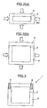
- FIG. 1 schematically shows the step of covering the rare earth magnet with an aluminum case in the method for manufacturing the sealed rare earth magnet according to one embodiment of the present invention. More specifically, by processing the aluminummaterial, it is possible to fabricate a case portion and a lid portion in which the magnet is inserted. Subsequently, as shown in FIG. 1 , by inserting a rare earth magnet 2 into an aluminum case portion 4 and shutting the open portion of the case portion with a lid portion 5, the rare earth magnet can be covered by the aluminum case.
- the rare earth magnet can be magnetized before or after the step of covering with the aluminum case. In the latter case, it is possible to cover the rare earth magnet material with the aluminum case. In a similar manner, the rare earth magnet can be magnetized before or after the step of sealing with HIP processing.
- the concentration of oxygen in the magnet is 100 to 10,000 ppm and is more preferably 500 to 6,000 ppm.
- concentration of hydrogen in the magnet is 50 ppm or less, and is more preferably 10 ppm or less.
- the sealed rare earth magnet manufactured according to the present invention is sealed by HIP processing.
- HIP processing is also known as hot isostatic pressing or hot isotropic pressing, and is a technology in which an object to be processed is pressured by applying a high isotropic pressure at high temperature via a pressure medium such as a gas.
- FIG. 2 schematically shows horizontal (A) and vertical (B) cross-sectional views of the step of sealing the aluminum case by HIP processing, in the method for manufacturing the sealed rare earth magnet according to one embodiment of the present invention.
- the aluminum case comprises the case portion 4 and the lid portion 5 as described above.
- HIP processing is performed under the following conditions. That is to say, it is preferable that the processing temperature is 0.6 or more times the melting point of aluminum or the aluminum alloy (approximately 660°C), (for example, if the melting point is 600°C, the processing temperature is 396°C or greater) and less than or equal to the meltingpoint, and more specifically, is preferably 500 to 600°C. Furthermore, for the processing time, the longer the time, the further the joining becomes. More specifically, it is preferable that the processing time is 1 to 3 hours. Furthermore, it is preferable that the processing pressure is 1,000 to 2, 000 kg/cm 2 . Furthermore, it is preferable that the pressure medium for applying isotropic pressure to the object to be processed is a gas such as argon (Ar). This is because under these conditions the magnetic characteristics of the magnetic material are less liable to change.
- the processing temperature is 0.6 or more times the melting point of aluminum or the aluminum alloy (approximately 660°C), (for example, if the melting point is 600°C,
- the present invention by sealing by HIP processing, it is possible to completely seal a separated aluminum case and to prevent penetration of hydrogen without change in the magnetic properties of the magnet material. Specifically, with the present invention, because the permanent magnet is completely sealed by aluminum, there is no contact between the magnet and hydrogen gas. On the other hand, since processes such as CIP (Cold Isostatic Pressing) do not ensure good contact of the separated aluminum case, they cannot prevent the penetration of hydrogen gas.
- CIP Cold Isostatic Pressing
- HIP processing is preferable because pinholes can be prevented.
- Welding is an example of a method for sealing the case.
- welding is not preferable, since it cannot prevent pinholes, and hydrogen may penetrate through the pinholes.
- HIP processing has the effect of pressing out and removing air holes within the material, pinholes are not substantially present in the case of the present invention. It should be noted that the presence or absence of pinholes can be confirmed as follows. That is to say, they can be measured by visual inspection, or by devices such as detection devices that use CCD image analysis or detection devices that use low frequency pulses.
- FIG. 3 schematically shows a frontal view of the sealed rare earth magnet manufactured according to one embodiment of the present invention.
- a sealed magnet 1 shown in FIG. 3 is an example in which tap holes 6 have been opened by machining in an aluminum case 3 covering the magnet 2. Since the rare earth magnet is a sintered body, and thus has mechanically fragile characteristics, the magnet can not be tapped.
- tap holes can be provided in the aluminum case, and thus it is possible to mechanically fix the rare earth magnet to a device.
- alumite treatment it is possible to improve properties such as the corrosion resistance, hardness, abrasion resistance and heat resistance of the sealed rare earth magnet.
- the conditions for alumite treatment can be arranged by one skilled in the art as appropriate in accordance with the object as exemplified as follows. That is to say it may be processed by degreasing, rinsing, etching, rinsing, neutralizing, electrolyzing (alumite treatment), rinsing, colouring, rinsing, sealing, hot water rinsing and drying.
- the sealedmagnet according to the present invention can prevent hydrogen embrittlement, and can be effectively used in a wide range of fields such as magnetic circuits, motors and semiconductor manufacturing devices.
- the sealed magnet manufactured according to the present invention utilized in a rotor of a four pole IPM (interior permanent magnet) motor is illustrated.
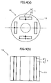
- FIG. 4 schematically shows a rotor of a four pole IPM motor, wherein the sealed magnet according to the present invention is utilized.
- it is possible to provide a rotor 10 of the motor by providing rectangular holes in a rotor yoke 11 and inserting magnetized magnets into these holes, as illustrated in FIG. 4 .
- the ring-shaped rotor yoke 11 has a plurality of openings for inserting the sealed magnet 1 according to the present invention.
- the openings are disposed concentrically with the rotor yoke in regular intervals.
- the sealed magnets manufactured according to the present invention comprising the rare earth magnets 2 sealed in the aluminum cases 3 are inserted in the openings.
- the magnetization direction of the each magnet is the radial direction, and is opposite of adjacent magnets.
- the magnetization direction of the magnets is indicated by arrows.
- the magnetization of the magnets may be carried out after the step of sealing by HIP processing and before assembling the rotor, or after assembling the rotor. That is to say, magnetized sealed magnets may be inserted in the rotor yoke, or if a dedicated magnetization jig is prepared, magnetization may be performed after inserting the magnets into the rotor yoke.
- sealed magnets were manufactured as given below. That is to say, as schematically shown in FIG. 2 , an aluminum case comprising a case portion and a lid portion was used.
- a material of aluminum alloy A6061 was used for the aluminum case.
- a Sm 2 Co 17 magnet was used as the R 2 Co 17 -based magnet
- an Nd 2 -Fe 14 -B magnet was used as the R-Fe-B-based magnet.
- Ar gas was used as the pressure medium and processing was performed for 1 hour at a pressure of 1000 kg/cm 2 and a temperature of 500°C.
- 500°C is the lower limit of the heat treatment temperature of the magnet, namely, it corresponds to the heat treatment temperature for generating the magnetic properties of the ND 2 -Fe 14 -B magnet, but since the processing time was about one hour, there were no changes in the magnetic properties.
- the working example in which the Sm 2 Co 17 magnet was used is taken as working example 1
- the working example in which the Nd 2 -Fe 14 -Bmagnet was used is taken as working example 2.
- Sm 2 Co 17 magnets wherein the magnet has had no surface treatment (comparative example 1), wherein the magnet is nickel plated with a film thickness of 20 ⁇ m (comparative example 2), and wherein the magnet is copper plated with a film thickness of 20 ⁇ m (comparative example 3) were used.
- Nd 2 -Fe 14 -B magnets wherein the magnet has had no surface treatment (comparative example 4), wherein the magnet is nickel plated with a film thickness of 20 ⁇ m (comparative example 5), and wherein the magnet is copper plated with a film thickness of 20 ⁇ m (comparative example 6) were used.
- the sealed magnets according to the working examples, and the magnets according to the comparative examples were exposed at a pressure of 3 MPa for one day, or at a higher pressure of 15 MPa for one day or for seven days, subsequently observing the state of the magnets.
- the test temperature was 25°C, and the results are shown in Table 1.
- the present invention by covering the surface of a rare earth magnet with an aluminum case and sealing the permanent magnet by HIP processing, it is possible to increase the hydrogen gas resistivity of the rare earth magnet in a hydrogen gas atmosphere. Thus, it is possible to widen the range of environments in which the rare earth magnet can be used. Furthermore, in semiconductor manufacturing devices, by treating the surface of the rare earth magnet, there is no contamination of the reaction bath.
Landscapes
- Engineering & Computer Science (AREA)
- Power Engineering (AREA)
- Physics & Mathematics (AREA)
- Electromagnetism (AREA)
- Environmental & Geological Engineering (AREA)
- Manufacturing & Machinery (AREA)
- Manufacturing Cores, Coils, And Magnets (AREA)
- Hard Magnetic Materials (AREA)
- Powder Metallurgy (AREA)
Claims (5)
- Verfahren zur Herstellung eines versiegelten Seltenerdmagneten, wobei das Verfahren die Schritte umfaßt:Bedecken eines geformten und gesinterten Seltenerdmagneten oder eines Seltenerdmagnet-Materials mit einem Gehäuse aus Aluminium oder Aluminiumlegierung, wobei das Gehäuse einen Gehäuseteil und einen Deckelteil umfaßt undVersiegeln des Gehäuses durch Verbinden des Gehäuseteils und des Deckelteils durch HIP bei einer Verfahrenstemperatur zwischen dem 0,6-fachen oder mehr der Schmelztemperatur des Aluminiums oder der Aluminiumlegierung und einer niedrigeren oder der gleichen Temperatur wie die Schmelztemperatur undAlumit-Behandlung oder Bearbeitung des versiegelten Gehäuses,worin das Eindringen eines Wasserstoffgases in den versiegelten Seltenerdmagneten verhindert werden kann.
- Verfahren zur Herstellung eines versiegelten Seltenerdmagneten nach Anspruch 1, worin die Verfahrenstemperatur 500 bis 600 °C ist.
- Verfahren zur Herstellung eines versiegelten Seltenerdmagneten nach Anspruch 1 oder 2, worin der Seltenerdmagnet ein R-Co-basierter oder R-Fe-B-basierter Seltenerdmagnet ist, worin R ein Seltenerdmetall ist.
- Verfahren zur Herstellung eines versiegelten Seltenerdmagneten nach einem der Ansprüche 1 bis 3, worin die Konzentration von Sauerstoff in dem Magneten 100 - 10.000 ppm ist, wenn der Seltenerdmagnet oder das Seltenerdmagnet-Material mit dem Gehäuse bedeckt wird.
- Verfahren zur Herstellung eines inneren Permanentmagnet(IPM)-Motors, umfassend einen Schritt des Einsetzens des versiegelten Seltenerdmagneten, erhalten nach dem Verfahren gemäß einem der Ansprüche 1 bis 4, in Öffnungen eines Läuferjochs.
Applications Claiming Priority (2)
| Application Number | Priority Date | Filing Date | Title |
|---|---|---|---|
| JP2004050980A JP4583048B2 (ja) | 2004-02-26 | 2004-02-26 | 希土類磁石密封体およびipmモータの製造方法 |
| JP2004050980 | 2004-02-26 |
Publications (3)
| Publication Number | Publication Date |
|---|---|
| EP1569251A2 EP1569251A2 (de) | 2005-08-31 |
| EP1569251A3 EP1569251A3 (de) | 2011-07-06 |
| EP1569251B1 true EP1569251B1 (de) | 2013-04-24 |
Family
ID=34747491
Family Applications (1)
| Application Number | Title | Priority Date | Filing Date |
|---|---|---|---|
| EP05251041.9A Ceased EP1569251B1 (de) | 2004-02-26 | 2005-02-23 | Versiegelter Seltenerdmagnet und Verfahren zu seiner Herstellung |
Country Status (3)
| Country | Link |
|---|---|
| US (2) | US7391291B2 (de) |
| EP (1) | EP1569251B1 (de) |
| JP (1) | JP4583048B2 (de) |
Families Citing this family (19)
| Publication number | Priority date | Publication date | Assignee | Title |
|---|---|---|---|---|
| DE202004006618U1 (de) * | 2004-04-26 | 2005-09-08 | Mtk Magnettechnik Gmbh & Co.Kg | Haftmagnet |
| US8362864B2 (en) * | 2005-10-06 | 2013-01-29 | Micro Motion, Inc. | Magnet assembly |
| US8012442B2 (en) * | 2006-03-31 | 2011-09-06 | Tokyo Electron Limited | Method of forming mixed rare earth nitride and aluminum nitride films by atomic layer deposition |
| US7816737B2 (en) * | 2006-03-31 | 2010-10-19 | Tokyo Electron Limited | Semiconductor device with gate dielectric containing mixed rare earth elements |
| DK2017859T3 (da) | 2007-07-20 | 2012-09-17 | Siemens Ag | Magnetpolemne og fremgangsmåde til fremstilling heraf |
| US7985363B2 (en) * | 2008-02-12 | 2011-07-26 | Mack Molding Company | Method of encasing a magnet |
| NL1036543A1 (nl) * | 2008-02-20 | 2009-08-24 | Asml Netherlands Bv | Lithographic apparatus comprising a magnet, method for the protection of a magnet in a lithographic apparatus and device manufacturing method. |
| IL195829A0 (en) * | 2008-12-10 | 2009-09-01 | Dan Bashi | Magnet car |
| DE102009008209A1 (de) * | 2009-02-10 | 2010-08-19 | Carl Zeiss Smt Ag | Aktuator mit mindestens einem Magneten für eine Projektionsbelichtungsanlage sowie Projektionsbelichtungsanlage mit einem Magneten und Herstellungsverfahren hierfür |
| FI20105724L (fi) * | 2010-06-23 | 2011-12-24 | Abb Oy | Järjestely ja menetelmä kestomagneetin suojaamiseksi |
| JP6117706B2 (ja) * | 2012-01-04 | 2017-04-19 | トヨタ自動車株式会社 | 希土類ナノコンポジット磁石 |
| JP2016047222A (ja) * | 2014-08-27 | 2016-04-07 | 光昭 井原 | 磁気封入アルミ盤 |
| CN104651783B (zh) | 2015-02-12 | 2017-09-01 | 烟台首钢磁性材料股份有限公司 | 一种永磁钕铁硼磁钢表面镀铝的方法 |
| WO2017031429A1 (en) * | 2015-08-20 | 2017-02-23 | Xtalic Corporation | Magnets including an aluminum manganese alloy coating layer and related methods |
| WO2018125856A1 (en) * | 2016-12-30 | 2018-07-05 | Smith & Nephew, Inc. | Actuation system and method for orthopedic implants with a rotatable internal magnet |
| US20190074121A1 (en) * | 2017-07-10 | 2019-03-07 | Xtalic Corporation | Magnets comprising a coating including an aluminum layer |
| CN108899190B (zh) * | 2018-06-29 | 2020-12-22 | 烟台首钢磁性材料股份有限公司 | 一种梯度钕铁硼磁体及其制作方法 |
| CN110159460A (zh) * | 2019-06-25 | 2019-08-23 | 王隆曦 | 一种发动机燃油优化器及优化器稀土磁体的制备方法 |
| KR20250157424A (ko) * | 2023-03-03 | 2025-11-04 | 콩스베르그 마리타임 에이에스 | 영구 자석 스러스트들 내 자석들의 금속 캡슐화 |
Family Cites Families (31)
| Publication number | Priority date | Publication date | Assignee | Title |
|---|---|---|---|---|
| JPS5337898A (en) * | 1976-09-20 | 1978-04-07 | Seiko Epson Corp | Permanent magnet of enclosed construction |
| US4647891A (en) * | 1984-12-17 | 1987-03-03 | Hughes Richard E | Encapsulated magnet and method of forming same |
| JPH07113551B2 (ja) * | 1986-07-21 | 1995-12-06 | ティーディーケイ株式会社 | 傾斜センサ |
| US4769624A (en) * | 1986-10-30 | 1988-09-06 | General Motors Corporation | Permanent magnet assembly |
| JPS63130280A (ja) * | 1986-11-20 | 1988-06-02 | Toshiba Corp | 接合方法 |
| EP0309831A1 (de) * | 1987-09-29 | 1989-04-05 | Siemens Aktiengesellschaft | Ionensperrschicht auf Metallen und Nichtmetallen |
| JP2603492B2 (ja) * | 1987-12-26 | 1997-04-23 | ティーディーケイ株式会社 | 傾斜センサ |
| JPH01261806A (ja) * | 1988-04-13 | 1989-10-18 | Daido Steel Co Ltd | 希土類磁石とその製造方法 |
| US4810987A (en) * | 1988-06-27 | 1989-03-07 | Liebthal Siegfried G V | One piece molded magnet enclosure |
| JPH03173105A (ja) * | 1989-11-30 | 1991-07-26 | Shin Etsu Chem Co Ltd | 耐食性被膜を有する希土類永久磁石とその製造方法 |
| US5337033A (en) * | 1991-06-13 | 1994-08-09 | Hitachi Metals, Ltd. | Permanent magnet assembly for stably fixing denture |
| JPH0529116A (ja) * | 1991-07-18 | 1993-02-05 | Kobe Steel Ltd | 高耐食性希土類磁石 |
| JPH05143972A (ja) | 1991-11-19 | 1993-06-11 | Kubota Corp | 金属薄膜型磁気記録媒体およびその製造法 |
| US5456769A (en) * | 1993-03-10 | 1995-10-10 | Kabushiki Kaisha Toshiba | Magnetic material |
| JPH06284610A (ja) * | 1993-03-31 | 1994-10-07 | Toshiba Corp | 永久磁石式回転電機 |
| JPH07272913A (ja) * | 1994-03-30 | 1995-10-20 | Kawasaki Teitoku Kk | 永久磁石原料、その製造法及び永久磁石 |
| US5750044A (en) * | 1994-07-12 | 1998-05-12 | Tdk Corporation | Magnet and bonded magnet |
| WO1998031497A1 (en) * | 1997-01-20 | 1998-07-23 | Kabushiki Kaisha Meidensha | Unified junction structure of rare-earth magnet and metal material and the jointing method |
| JPH10277545A (ja) * | 1997-04-02 | 1998-10-20 | Takashi Matsuzaka | 磁気と遠赤外線を利用した水処理装置および治療器 |
| JPH1187119A (ja) | 1997-09-01 | 1999-03-30 | Yaskawa Electric Corp | 表面処理膜付磁石 |
| JPH11151252A (ja) * | 1997-11-25 | 1999-06-08 | Aichi Steel Works Ltd | 歯根挺出装置 |
| EP0961102A4 (de) * | 1997-12-09 | 2002-11-06 | Matsushita Electric Industrial Co Ltd | Neigungssensor |
| CN1144240C (zh) * | 1998-03-27 | 2004-03-31 | 东芝株式会社 | 磁性材料 |
| US6299450B1 (en) * | 1998-04-23 | 2001-10-09 | Aichi Steel Corporation | Dental magnetic attachment |
| JP3620375B2 (ja) * | 1999-10-22 | 2005-02-16 | トヨタ自動車株式会社 | 磁性体の設置方法、磁性式標識体及び車両用情報取得装置 |
| JP2002208529A (ja) * | 2000-03-07 | 2002-07-26 | Shunichi Haruyama | リング状磁石の製造方法とリング状磁石用素材並びに切削用樹脂 |
| WO2002089153A1 (en) | 2001-04-24 | 2002-11-07 | Asahi Kasei Kabushiki Kaisha | Solid material for magnet |
| JP4126947B2 (ja) * | 2002-04-24 | 2008-07-30 | 住友金属鉱山株式会社 | 耐塩水性磁石合金粉、その製造方法及びそれを用いて得られるボンド磁石用樹脂組成物、ボンド磁石又は圧密磁石 |
| US6974543B2 (en) * | 2003-01-16 | 2005-12-13 | Jen Chien Wang | Magnetic-energy-releasing molecular rearranging structure |
| JP2005168692A (ja) * | 2003-12-10 | 2005-06-30 | Shin Etsu Chem Co Ltd | 永久磁石対向型磁気回路およびその磁場を調整する方法 |
| JP2005223263A (ja) * | 2004-02-09 | 2005-08-18 | Sumitomo Metal Mining Co Ltd | 希土類永久磁石の製造方法及び得られた希土類永久磁石 |
-
2004
- 2004-02-26 JP JP2004050980A patent/JP4583048B2/ja not_active Expired - Fee Related
-
2005
- 2005-02-22 US US11/063,008 patent/US7391291B2/en not_active Expired - Lifetime
- 2005-02-23 EP EP05251041.9A patent/EP1569251B1/de not_active Ceased
-
2008
- 2008-05-16 US US12/121,895 patent/US20080218298A1/en not_active Abandoned
Also Published As
| Publication number | Publication date |
|---|---|
| JP4583048B2 (ja) | 2010-11-17 |
| US20050190031A1 (en) | 2005-09-01 |
| EP1569251A3 (de) | 2011-07-06 |
| US7391291B2 (en) | 2008-06-24 |
| EP1569251A2 (de) | 2005-08-31 |
| JP2005243882A (ja) | 2005-09-08 |
| US20080218298A1 (en) | 2008-09-11 |
Similar Documents
| Publication | Publication Date | Title |
|---|---|---|
| US20080218298A1 (en) | Sealed Rare Earth Magnet and Method for Manufacturing the Same | |
| EP1467385B1 (de) | Gesinterter seltenerdelementmagnet und verfahren zur herstellung eines gesinterten seltenerdelementmagneten | |
| JP4036344B2 (ja) | 希土類磁石と金属材料の一体接合構造物及びその接合方法 | |
| EP2372726B1 (de) | Seltenerdmagnet, Herstellungsverfahren für den Seltenerdmagnet und Rotor | |
| EP2555206B1 (de) | Seltenerd-sintermagnet, verfahren zu seiner herstellung sowie motor und automobil damit | |
| EP1267365B1 (de) | Korrosionswiderstandsfähiger Seltenerdmetallmagnet und Herstellungsverfahren | |
| EP0361308A1 (de) | Korrosionsfester Dauermagnet und Herstellungsverfahren | |
| US8449696B2 (en) | Rare-earth sintered magnet containing a nitride, rotator containing rare-earth sintered magnet, and reciprocating motor containing rare-earth sintered magnet | |
| EP2518742B1 (de) | R-T-B-System-Dauermagnet | |
| JP5708116B2 (ja) | 希土類磁石 | |
| JP5024531B2 (ja) | 希土類焼結磁石の使用方法 | |
| JP2005310975A (ja) | 焼結ネオジム磁石および製造方法、回転電機 | |
| JP5273012B2 (ja) | 希土類磁石 | |
| JP5348110B2 (ja) | 希土類磁石、希土類磁石の製造方法及び回転機 | |
| EP0923087B1 (de) | Korrosionsfeste dauermagnet und herstellungsverfahren | |
| EP1814128B1 (de) | Gesinterter seltenerd-magnet | |
| JP2005285793A (ja) | 希土類磁石、その製造方法、及び多層体の製造方法 | |
| JP3993613B2 (ja) | 磁石及びその製造方法 | |
| JP2721187B2 (ja) | R−F▲下e▼−B−M系焼結磁石およびその製造方法 | |
| JP2006156853A (ja) | 希土類磁石 | |
| JP5348109B2 (ja) | 希土類磁石、希土類磁石の製造方法及び回転機 | |
| JP2003338419A (ja) | R−tm−b系永久磁石 | |
| JP2004289021A (ja) | 希土類磁石の製造方法 | |
| JP5672798B2 (ja) | 希土類磁石 | |
| JP2007273556A (ja) | 磁石 |
Legal Events
| Date | Code | Title | Description |
|---|---|---|---|
| PUAI | Public reference made under article 153(3) epc to a published international application that has entered the european phase |
Free format text: ORIGINAL CODE: 0009012 |
|
| AK | Designated contracting states |
Kind code of ref document: A2 Designated state(s): AT BE BG CH CY CZ DE DK EE ES FI FR GB GR HU IE IS IT LI LT LU MC NL PL PT RO SE SI SK TR |
|
| AX | Request for extension of the european patent |
Extension state: AL BA HR LV MK YU |
|
| PUAL | Search report despatched |
Free format text: ORIGINAL CODE: 0009013 |
|
| AK | Designated contracting states |
Kind code of ref document: A3 Designated state(s): AT BE BG CH CY CZ DE DK EE ES FI FR GB GR HU IE IS IT LI LT LU MC NL PL PT RO SE SI SK TR |
|
| AX | Request for extension of the european patent |
Extension state: AL BA HR LV MK YU |
|
| 17P | Request for examination filed |
Effective date: 20111115 |
|
| AKX | Designation fees paid |
Designated state(s): DE FR GB |
|
| 17Q | First examination report despatched |
Effective date: 20120326 |
|
| GRAP | Despatch of communication of intention to grant a patent |
Free format text: ORIGINAL CODE: EPIDOSNIGR1 |
|
| RIN1 | Information on inventor provided before grant (corrected) |
Inventor name: MIYATA, KOJI, |
|
| GRAS | Grant fee paid |
Free format text: ORIGINAL CODE: EPIDOSNIGR3 |
|
| GRAA | (expected) grant |
Free format text: ORIGINAL CODE: 0009210 |
|
| AK | Designated contracting states |
Kind code of ref document: B1 Designated state(s): DE FR GB |
|
| REG | Reference to a national code |
Ref country code: GB Ref legal event code: FG4D |
|
| REG | Reference to a national code |
Ref country code: DE Ref legal event code: R096 Ref document number: 602005039223 Country of ref document: DE Effective date: 20130627 |
|
| PLBE | No opposition filed within time limit |
Free format text: ORIGINAL CODE: 0009261 |
|
| STAA | Information on the status of an ep patent application or granted ep patent |
Free format text: STATUS: NO OPPOSITION FILED WITHIN TIME LIMIT |
|
| 26N | No opposition filed |
Effective date: 20140127 |
|
| REG | Reference to a national code |
Ref country code: DE Ref legal event code: R097 Ref document number: 602005039223 Country of ref document: DE Effective date: 20140127 |
|
| REG | Reference to a national code |
Ref country code: FR Ref legal event code: PLFP Year of fee payment: 11 |
|
| REG | Reference to a national code |
Ref country code: FR Ref legal event code: PLFP Year of fee payment: 12 |
|
| REG | Reference to a national code |
Ref country code: FR Ref legal event code: PLFP Year of fee payment: 13 |
|
| REG | Reference to a national code |
Ref country code: FR Ref legal event code: PLFP Year of fee payment: 14 |
|
| PGFP | Annual fee paid to national office [announced via postgrant information from national office to epo] |
Ref country code: NL Payment date: 20181226 Year of fee payment: 13 |
|
| GBPC | Gb: european patent ceased through non-payment of renewal fee |
Effective date: 20200223 |
|
| PG25 | Lapsed in a contracting state [announced via postgrant information from national office to epo] |
Ref country code: GB Free format text: LAPSE BECAUSE OF NON-PAYMENT OF DUE FEES Effective date: 20200223 |
|
| PGFP | Annual fee paid to national office [announced via postgrant information from national office to epo] |
Ref country code: FR Payment date: 20210113 Year of fee payment: 17 |
|
| PGFP | Annual fee paid to national office [announced via postgrant information from national office to epo] |
Ref country code: DE Payment date: 20210209 Year of fee payment: 17 |
|
| REG | Reference to a national code |
Ref country code: DE Ref legal event code: R119 Ref document number: 602005039223 Country of ref document: DE |
|
| PG25 | Lapsed in a contracting state [announced via postgrant information from national office to epo] |
Ref country code: FR Free format text: LAPSE BECAUSE OF NON-PAYMENT OF DUE FEES Effective date: 20220228 |
|
| PG25 | Lapsed in a contracting state [announced via postgrant information from national office to epo] |
Ref country code: DE Free format text: LAPSE BECAUSE OF NON-PAYMENT OF DUE FEES Effective date: 20220901 |