EP1591187A2 - Verfahren zum Schweißen von beschichteten Blechen mittels eines Energiestrahls, wie eines Laserstrahls - Google Patents
Verfahren zum Schweißen von beschichteten Blechen mittels eines Energiestrahls, wie eines Laserstrahls Download PDFInfo
- Publication number
- EP1591187A2 EP1591187A2 EP05011079A EP05011079A EP1591187A2 EP 1591187 A2 EP1591187 A2 EP 1591187A2 EP 05011079 A EP05011079 A EP 05011079A EP 05011079 A EP05011079 A EP 05011079A EP 1591187 A2 EP1591187 A2 EP 1591187A2
- Authority
- EP
- European Patent Office
- Prior art keywords
- welding
- energy beam
- capillary
- vapor
- energy
- Prior art date
- Legal status (The legal status is an assumption and is not a legal conclusion. Google has not performed a legal analysis and makes no representation as to the accuracy of the status listed.)
- Granted
Links
Images

Classifications
-
- B—PERFORMING OPERATIONS; TRANSPORTING
- B23—MACHINE TOOLS; METAL-WORKING NOT OTHERWISE PROVIDED FOR
- B23K—SOLDERING OR UNSOLDERING; WELDING; CLADDING OR PLATING BY SOLDERING OR WELDING; CUTTING BY APPLYING HEAT LOCALLY, e.g. FLAME CUTTING; WORKING BY LASER BEAM
- B23K15/00—Electron-beam welding or cutting
- B23K15/0046—Welding
- B23K15/0053—Seam welding
-
- B—PERFORMING OPERATIONS; TRANSPORTING
- B23—MACHINE TOOLS; METAL-WORKING NOT OTHERWISE PROVIDED FOR
- B23K—SOLDERING OR UNSOLDERING; WELDING; CLADDING OR PLATING BY SOLDERING OR WELDING; CUTTING BY APPLYING HEAT LOCALLY, e.g. FLAME CUTTING; WORKING BY LASER BEAM
- B23K26/00—Working by laser beam, e.g. welding, cutting or boring
- B23K26/02—Positioning or observing the workpiece, e.g. with respect to the point of impact; Aligning, aiming or focusing the laser beam
- B23K26/04—Automatically aligning, aiming or focusing the laser beam, e.g. using the back-scattered light
-
- B—PERFORMING OPERATIONS; TRANSPORTING
- B23—MACHINE TOOLS; METAL-WORKING NOT OTHERWISE PROVIDED FOR
- B23K—SOLDERING OR UNSOLDERING; WELDING; CLADDING OR PLATING BY SOLDERING OR WELDING; CUTTING BY APPLYING HEAT LOCALLY, e.g. FLAME CUTTING; WORKING BY LASER BEAM
- B23K26/00—Working by laser beam, e.g. welding, cutting or boring
- B23K26/02—Positioning or observing the workpiece, e.g. with respect to the point of impact; Aligning, aiming or focusing the laser beam
- B23K26/06—Shaping the laser beam, e.g. by masks or multi-focusing
-
- B—PERFORMING OPERATIONS; TRANSPORTING
- B23—MACHINE TOOLS; METAL-WORKING NOT OTHERWISE PROVIDED FOR
- B23K—SOLDERING OR UNSOLDERING; WELDING; CLADDING OR PLATING BY SOLDERING OR WELDING; CUTTING BY APPLYING HEAT LOCALLY, e.g. FLAME CUTTING; WORKING BY LASER BEAM
- B23K26/00—Working by laser beam, e.g. welding, cutting or boring
- B23K26/02—Positioning or observing the workpiece, e.g. with respect to the point of impact; Aligning, aiming or focusing the laser beam
- B23K26/06—Shaping the laser beam, e.g. by masks or multi-focusing
- B23K26/064—Shaping the laser beam, e.g. by masks or multi-focusing by means of optical elements, e.g. lenses, mirrors or prisms
-
- B—PERFORMING OPERATIONS; TRANSPORTING
- B23—MACHINE TOOLS; METAL-WORKING NOT OTHERWISE PROVIDED FOR
- B23K—SOLDERING OR UNSOLDERING; WELDING; CLADDING OR PLATING BY SOLDERING OR WELDING; CUTTING BY APPLYING HEAT LOCALLY, e.g. FLAME CUTTING; WORKING BY LASER BEAM
- B23K26/00—Working by laser beam, e.g. welding, cutting or boring
- B23K26/02—Positioning or observing the workpiece, e.g. with respect to the point of impact; Aligning, aiming or focusing the laser beam
- B23K26/06—Shaping the laser beam, e.g. by masks or multi-focusing
- B23K26/064—Shaping the laser beam, e.g. by masks or multi-focusing by means of optical elements, e.g. lenses, mirrors or prisms
- B23K26/0643—Shaping the laser beam, e.g. by masks or multi-focusing by means of optical elements, e.g. lenses, mirrors or prisms comprising mirrors
-
- B—PERFORMING OPERATIONS; TRANSPORTING
- B23—MACHINE TOOLS; METAL-WORKING NOT OTHERWISE PROVIDED FOR
- B23K—SOLDERING OR UNSOLDERING; WELDING; CLADDING OR PLATING BY SOLDERING OR WELDING; CUTTING BY APPLYING HEAT LOCALLY, e.g. FLAME CUTTING; WORKING BY LASER BEAM
- B23K26/00—Working by laser beam, e.g. welding, cutting or boring
- B23K26/02—Positioning or observing the workpiece, e.g. with respect to the point of impact; Aligning, aiming or focusing the laser beam
- B23K26/06—Shaping the laser beam, e.g. by masks or multi-focusing
- B23K26/0665—Shaping the laser beam, e.g. by masks or multi-focusing by beam condensation on the workpiece, e.g. for focusing
-
- B—PERFORMING OPERATIONS; TRANSPORTING
- B23—MACHINE TOOLS; METAL-WORKING NOT OTHERWISE PROVIDED FOR
- B23K—SOLDERING OR UNSOLDERING; WELDING; CLADDING OR PLATING BY SOLDERING OR WELDING; CUTTING BY APPLYING HEAT LOCALLY, e.g. FLAME CUTTING; WORKING BY LASER BEAM
- B23K26/00—Working by laser beam, e.g. welding, cutting or boring
- B23K26/20—Bonding
- B23K26/21—Bonding by welding
- B23K26/24—Seam welding
- B23K26/244—Overlap seam welding
-
- B—PERFORMING OPERATIONS; TRANSPORTING
- B23—MACHINE TOOLS; METAL-WORKING NOT OTHERWISE PROVIDED FOR
- B23K—SOLDERING OR UNSOLDERING; WELDING; CLADDING OR PLATING BY SOLDERING OR WELDING; CUTTING BY APPLYING HEAT LOCALLY, e.g. FLAME CUTTING; WORKING BY LASER BEAM
- B23K26/00—Working by laser beam, e.g. welding, cutting or boring
- B23K26/20—Bonding
- B23K26/32—Bonding taking account of the properties of the material involved
-
- B—PERFORMING OPERATIONS; TRANSPORTING
- B23—MACHINE TOOLS; METAL-WORKING NOT OTHERWISE PROVIDED FOR
- B23K—SOLDERING OR UNSOLDERING; WELDING; CLADDING OR PLATING BY SOLDERING OR WELDING; CUTTING BY APPLYING HEAT LOCALLY, e.g. FLAME CUTTING; WORKING BY LASER BEAM
- B23K2101/00—Articles made by soldering, welding or cutting
- B23K2101/18—Sheet panels
-
- B—PERFORMING OPERATIONS; TRANSPORTING
- B23—MACHINE TOOLS; METAL-WORKING NOT OTHERWISE PROVIDED FOR
- B23K—SOLDERING OR UNSOLDERING; WELDING; CLADDING OR PLATING BY SOLDERING OR WELDING; CUTTING BY APPLYING HEAT LOCALLY, e.g. FLAME CUTTING; WORKING BY LASER BEAM
- B23K2101/00—Articles made by soldering, welding or cutting
- B23K2101/34—Coated articles ; Surface treated articles
-
- B—PERFORMING OPERATIONS; TRANSPORTING
- B23—MACHINE TOOLS; METAL-WORKING NOT OTHERWISE PROVIDED FOR
- B23K—SOLDERING OR UNSOLDERING; WELDING; CLADDING OR PLATING BY SOLDERING OR WELDING; CUTTING BY APPLYING HEAT LOCALLY, e.g. FLAME CUTTING; WORKING BY LASER BEAM
- B23K2103/00—Materials to be soldered, welded or cut
- B23K2103/02—Iron or ferrous alloys
-
- B—PERFORMING OPERATIONS; TRANSPORTING
- B23—MACHINE TOOLS; METAL-WORKING NOT OTHERWISE PROVIDED FOR
- B23K—SOLDERING OR UNSOLDERING; WELDING; CLADDING OR PLATING BY SOLDERING OR WELDING; CUTTING BY APPLYING HEAT LOCALLY, e.g. FLAME CUTTING; WORKING BY LASER BEAM
- B23K2103/00—Materials to be soldered, welded or cut
- B23K2103/08—Non-ferrous metals or alloys
-
- B—PERFORMING OPERATIONS; TRANSPORTING
- B23—MACHINE TOOLS; METAL-WORKING NOT OTHERWISE PROVIDED FOR
- B23K—SOLDERING OR UNSOLDERING; WELDING; CLADDING OR PLATING BY SOLDERING OR WELDING; CUTTING BY APPLYING HEAT LOCALLY, e.g. FLAME CUTTING; WORKING BY LASER BEAM
- B23K2103/00—Materials to be soldered, welded or cut
- B23K2103/50—Inorganic materials other than metals or composite materials
Definitions
- the present invention relates to a welding method of sheets coated with a beam of energy, such as example a laser beam.
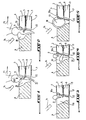
- Figures 1 and 2 show the welding by a laser beam 1, which operates in pulsed or continuous mode, two metal sheets 2, 3 respectively comprising on their two opposite sides two zinc coatings 4, 5; 6, 7 and kept tight against each other by all appropriate medium in the vicinity of the location of the weld so that the two internal coatings 5, 6 are between two plates 2, 3.
- a weld bead 8 is made to bind the sheets 2, 3 to each other and a passage 9, called capillary, is formed in the molten metal zone 10.
- the level beam energy is not necessarily zero and that can still contribute to welding.
- the reference 14 means a device for supplying gas directed towards the bath liquid 10 and known per se.
- Another known solution is to remove the zinc coating at the weld spot and the replace with a different coating, such as for example a nickel alloy.
- This solution has the disadvantage to incur an additional cost and to be complex because there is a different coating in some parts of the sheets.
- the sheets to solder are arranged vertically and the beam welding energy moves up and down so that the molten material flows by gravity, which has the effect improve the evacuation of zinc vapor.
- This solution requires special editing so that plates are arranged vertically and possibly in the case of complex parts and / or large dimensions such as motor vehicle doors, modify the orientation of the piece so that the energy beam of welding always moves from the bottom up.
- the present invention aims to eliminate the disadvantages above known solutions by putting in a process for welding coated sheets using a beam of energy that allows to obtain a good quality welding without adapting the geometry of the parts and without using additional equipment more or less complicated to maintain the sheets to be welded.
- the invention proposes a welding method by a beam of energy of sheets coated with a material having a lower evaporation temperature than melting temperature of the sheet material according to the Claim 1, 2 or 3.
- the energy beam allowing promote the evacuation of steam from the material of the coating is the welding energy beam.
- the process detects or anticipates a modification of the surface of the melt and to control the beam of energy so that the impulses emitted by it can make a hole in the melt when a determined heave of the surface of this material has been detected or has been planned in order to evacuate vapor of the coating material present in a pocket of the melt.
- the operation of drilling the surface of the material melted is done by decreasing the width of each pause pulse between two consecutive pulses of welding of the energy beam or introducing a additional impulse for the duration of each pause pulse between two consecutive pulses of welding of the energy beam.
- the detection of the modification of the surface of the melt is done by a source emission of an incident beam directed to the material weld fuse and a detector capable of measuring variations, directional, intensity or form, of beam reflected by the surface of the melt, this incident beam being advantageously a laser beam and the detector being advantageously a photodiode.
- the prediction of modification of the surface of the melted matter by measuring the amount of steam evacuated from the coating material during welding and in comparing to a predetermined amount of vapor to be evacuated of this material, measuring the amount of vapor evacuated preferably taking place by a spectroscopic method.
- the process involves controlling the energy beam so that the pulses emitted by it are adapted to drill any pocket of material vapor the coating present in the weldable melt during each pause pulse between two pulses of consecutive welding of the energy beam in order to evacuate the vapor of the coating material.
- the method consists in controlling the beam of energy so that the impulses emitted by it are adapted to put in permanent communication, during each pause pulse between two pulses consecutive welding of the energy beam, the capillary and the tunnel formed by the vapor pressure of the coating material in the melted interface zone of two sheets to be welded in order to obtain an evacuation of the steam of this material during each pause pulse.
- the method consists of decrease the width of each pause pulse of the beam of energy or to introduce a pulse additional during the duration of each pulse of pause the energy beam to pierce the steam pocket above or maintain communication between the capillary and the aforementioned tunnel.
- the beam has a cross section substantially elliptical whose major axis is directed in the direction of movement of the energy beam of welding.
- the beam aforementioned energy is inclined relative to the horizontal to produce the elliptical capillary.
- the aforementioned energy beam oscillates in the direction of the Welding energy beam to produce the capillary elliptical.
- Each aforementioned energy beam is preferably a laser beam.
- the method of the invention for welding sheet metal coated with a beam of energy such as laser beam or an electron beam, avoiding the ejections of the metal bath, is described with reference to two different embodiments, one using a Welding energy beam operating in pulsed mode and the other using such a working beam as well in pulsed mode only in continuous mode.
- the source 15 is different from the source 17 for welding and there is also a detector 18, such as for example a photodiode, allowing measure the variations, directional, intensity or shape, the beam 19 reflected by the surface of the bath 10.
- the electrical signals provided by the detector 18 and representative of such variations, are applied to a processing circuit (not shown) suitable to control the source 17 or an auxiliary source of a beam of energy so that the pulses emitted by it allow to pierce the pocket of zinc vapor 13 at through the liquid bath 10 and evacuate to the outside the zinc vapor when the surface of the liquid bath 10 has raised to a certain height. More precisely, when the surface of the liquid bath 10 is raised by the pocket 13 as shown in FIG. 7, the reflected beam 19 can be deflected by the curved surface of the bath 10 so that it does not hit the detector 18 or the to strike from a different angle.
- the detector 18 no longer provides an electrical signal or provides a modified signal so that the circuit of processing controls the source 17 or the source annex for that the energy beam realizes, during the duration Tp of each pulse pulse Ip of the pulse train represented in FIG. 9 between two welding pulses successive Is, a hole 20 in the upper layer of liquid bath 10 and opening into the pocket 13 (Figure 8).
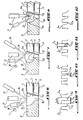
- Such drilling can be done during each pulse of pause by decreasing the width of the pulse duration of Ip pause as shown in Tp1 in Figure 10 or in introducing during the duration Tp of the pause pulse of low level Ip an extra impulse Ip2 like shown in Figure 11 and a width and a level defined in order to pierce only the part in liquid bath bubble shape 10 to reach the pocket 13.
- FIGS. 6 to 8 show the auxiliary source of laser beam 21 used for promote the evacuation of zinc vapor and preferably located at the back of capillary 9 because it has been found that the vapors are evacuated more easily behind this capillary.
- the piercing of the pocket of zinc vapor 13 at through the liquid bath 10 is carried out by detection at using appropriate means of the disappearance of wavelets on the surface of the liquid bath. Indeed, a possible swelling of the liquid bath smooth irregularities on the surface of it due to hydrodynamic agitations. Wavelets disappear or diminish under the action surface tension forces and the detection of any modification of the bath surface 10 may reveal a zinc vapor pocket formation 13.
- Such a information can be detected and processed as described in the previous embodiment variant by adapting the pulse train of the energy beam, preferably the welding beam, as shown in Figure 10 or in Figure 11.
- the piercing of the zinc vapor pocket 13 can be performed by providing for the lifting of the liquid bath 10 by measuring the amount of zinc vapor evacuated beforehand.
- the operation of welding results in evaporation, at the interface of the welding sheets 2, 3, a certain amount of coating of zinc. If the amount of zinc vapor evacuated during each pause pulse of the energy beam is less than the predetermined quantity to be evacuated, a ejection of the liquid bath 10 is predictable.
- the result of such a comparison is operated in such a way as to decrease the duration of each impulse pause as shown in Figure 10 or to introduce a extra impulse in the break pulse like shown in Figure 11 to achieve during each pause pulse steam evacuation piercing 20 of zinc present in the pocket 13.
- the amount of zinc evacuated during welding can be measured by a method spectroscopic after calibration by a steady-state analysis stable condition.
- the piercing 20 of the pocket of zinc vapor 13, instead of being carried out after detection real-time bath uplift 10 as explained in 6 to 8, can be realized in permanence, in a systematic way, in every cycle Ts + Tp welding pulse train emitted by the source welding energy 17 or the auxiliary source.
- Tp of the pause pulse Ip of this train pulses at least one suitably shaped pulse Ip2 can be introduced as shown in FIG. perform the drilling 20.
- the evacuation of the zinc vapor can also be done by maintaining communication between the capillary 9 of the liquid bath 10 and the tunnel 12 formed as explained previously with reference to FIGS. 2.
- the shape of the pulse train emitted by the energy beam welding or energy beam will be chosen so as to conform to that of the pulse train of Figure 11 or that of the train of pulses of Figure 12 which are train shapes pulses given by way of example. So, during each welding cycle, the pause pulse Ip is adapted to realize the connection or communication permanent between tunnel 12 and capillary 9 as shown in Figure 13.
- Figure 14 shows the beam pulsed energy supply 1 issued by the source welding or by the external source and whose pulses are generated according to the pulse train of the Figure 11 or Figure 12 to form the communication permanent between the tunnel 12 and the capillary 9.
- the energy beam for welding the coated sheets 2, 3 both in operating mode pulsed in continuous operation mode by improving the escape of the zinc vapor through the capillary 9 and thus avoiding the ejections of the liquid bath 10 is adapted to make capillary 9 so that it presents in cross section an elongated shape particularly substantially elliptical as shown in FIG. 15, the major axis of this elliptical shape being directed in beam moving direction of welding energy symbolized by arrow F1.
- the beam of energy to achieve the capillary elliptical 10 can be provided by the welding source or an external source and is preferably a laser beam.
- This elliptical section of capillary 10 is determined to allow a process of welding while lengthening the capillary so as not to disturb the release of the vapor from the coating, decrease the influence of metal vapor during its evacuation on the stability of the welding process and so increase flow through a larger section of the capillary 9. It was found that a stable capillary was obtained with an elongated section beam, which is not always the case with a beam of circular section.
- the elongated, in particular, elliptical shape of the capillary 9 can be achieved by different techniques.
- One of these techniques is to use a beam of energy to circular section but inclined relative to the face top of the sheet 2 so that the section horizontal of this beam is elliptical.
- Another technique consists in providing one or more lenses cylindrical or aspheric, one or more mirrors cylindrical or aspheric, or diffractive elements or any other similar device on the route of the beam of energy so as to generate the elliptical shape of the capillary 9 during the welding operation.
- FIG. 17 represents an optical system making it possible to produce an elliptical beam.
- This system comprises two cylindrical mirrors 22 and 23 forming in known manner a telescope so that the beam they form has a defined length to width ratio and a conventional parabolic mirror 24 which focuses this beam at a point.
- the distance d between the two mirrors 22 and 23 is adjustable and thus allows to have a focus along the major axis and the minor axis of the ellipse at the same location. In other words, the astigmatism can be adjusted, if necessary, to zero.
- This optical system is to have a focusing system and a system generating the report above independent of each other. We will be able to change report or change focus by keeping a report identical. It should be noted that the angles of incidence of the beam on the mirrors are optimized so the optical system is easily adjustable and minimizes optical aberrations.
- an optimization of the elliptical shape of the capillary 9 allows evacuation of zinc vapor without disturbing the metal bath 10 and increasing the vapor exhaust rate of the coating material.
- the intensity distribution in the section of the welding beam will be such that it allows welding while optimizing it to save money of energy we found that the best results are obtained with the beam intensity stronger at the front of it in relation to its direction of travel.
Landscapes
- Physics & Mathematics (AREA)
- Optics & Photonics (AREA)
- Engineering & Computer Science (AREA)
- Mechanical Engineering (AREA)
- Plasma & Fusion (AREA)
- Laser Beam Processing (AREA)
- Welding Or Cutting Using Electron Beams (AREA)
Applications Claiming Priority (3)
| Application Number | Priority Date | Filing Date | Title |
|---|---|---|---|
| FR9708223 | 1997-06-30 | ||
| FR9708223A FR2765129B1 (fr) | 1997-06-30 | 1997-06-30 | Procede de soudage de toles revetues par un faisceau d'energie, tel qu'un faisceau laser |
| EP98933751A EP0921895B1 (de) | 1997-06-30 | 1998-06-29 | Verfahren zum schweissen von beschichteten blechen mittels eines energiestrahles wie eines laserstrahles |
Related Parent Applications (2)
| Application Number | Title | Priority Date | Filing Date |
|---|---|---|---|
| EP98933751A Division EP0921895B1 (de) | 1997-06-30 | 1998-06-29 | Verfahren zum schweissen von beschichteten blechen mittels eines energiestrahles wie eines laserstrahles |
| EP98933751.4 Division | 1998-06-29 |
Publications (3)
| Publication Number | Publication Date |
|---|---|
| EP1591187A2 true EP1591187A2 (de) | 2005-11-02 |
| EP1591187A3 EP1591187A3 (de) | 2006-12-27 |
| EP1591187B1 EP1591187B1 (de) | 2010-11-03 |
Family
ID=9508648
Family Applications (2)
| Application Number | Title | Priority Date | Filing Date |
|---|---|---|---|
| EP05011079A Expired - Lifetime EP1591187B1 (de) | 1997-06-30 | 1998-06-29 | Verfahren zum Schweißen von beschichteten Blechen mittels eines Energiestrahls, wie eines Laserstrahls |
| EP98933751A Expired - Lifetime EP0921895B1 (de) | 1997-06-30 | 1998-06-29 | Verfahren zum schweissen von beschichteten blechen mittels eines energiestrahles wie eines laserstrahles |
Family Applications After (1)
| Application Number | Title | Priority Date | Filing Date |
|---|---|---|---|
| EP98933751A Expired - Lifetime EP0921895B1 (de) | 1997-06-30 | 1998-06-29 | Verfahren zum schweissen von beschichteten blechen mittels eines energiestrahles wie eines laserstrahles |
Country Status (8)
| Country | Link |
|---|---|
| US (1) | US6359252B1 (de) |
| EP (2) | EP1591187B1 (de) |
| JP (1) | JP4205175B2 (de) |
| DE (2) | DE69831382T2 (de) |
| ES (1) | ES2354301T3 (de) |
| FR (1) | FR2765129B1 (de) |
| PT (1) | PT1591187E (de) |
| WO (1) | WO1999001249A1 (de) |
Families Citing this family (23)
| Publication number | Priority date | Publication date | Assignee | Title |
|---|---|---|---|---|
| DE10218179A1 (de) * | 2002-04-24 | 2003-11-20 | Daimler Chrysler Ag | Verfahren und Einrichtung zum Schweißen von Werkstücken |
| EP1384544A1 (de) * | 2002-07-26 | 2004-01-28 | Behr Lorraine S.A.R.L. | Vorrichtung zum Loten eines Wärmeübertragers |
| US6932879B2 (en) * | 2002-08-13 | 2005-08-23 | Edison Welding Institute | Method of weldbonding |
| WO2005030426A2 (en) * | 2003-09-09 | 2005-04-07 | Matsushita Electric Industrial Co. Ltd. | System and method for laser welding foils |
| US20060000810A1 (en) * | 2004-06-30 | 2006-01-05 | Kerr James A | Method of and system for dynamic laser welding |
| DE102004041502B4 (de) * | 2004-08-27 | 2012-03-08 | Audi Ag | Überlappschweißverfahren mittels Strahlschweißung, insbesondere mittels Laserstrahlschweißung, an beschichteten Blechen, insbesondere an verzinkten Stahlblechen |
| JP2006095602A (ja) * | 2004-09-27 | 2006-04-13 | Dana Corp | 亜鉛めっき鋼部品の溶接方法 |
| US8253062B2 (en) * | 2005-06-10 | 2012-08-28 | Chrysler Group Llc | System and methodology for zero-gap welding |
| FR2892328B1 (fr) * | 2005-10-21 | 2009-05-08 | Air Liquide | Procede de soudage par faisceau laser avec controle de la formation du capillaire de vapeurs metalliques |
| EP1974849A1 (de) * | 2007-03-28 | 2008-10-01 | Trumpf Laser- und Systemtechnik GmbH | Verfahren zur Fixierung strukturgeklebter Werkstücke, insbesondere zum Laserschweißen von geklebten Werkstücken |
| DE102008006625B4 (de) * | 2008-01-29 | 2011-07-14 | ThyssenKrupp Steel Europe AG, 47166 | Verfahren und Vorrichtung zur Überwachung des Laserstrahlschweißens von beschichteten Platinen |
| JP4612076B2 (ja) * | 2008-04-24 | 2011-01-12 | 東亜工業株式会社 | 金属メッキ板のレーザー溶接方法 |
| FR2938781B1 (fr) * | 2008-11-27 | 2012-06-01 | Renault Sas | Procede de fabrication d'un corps creux en tole zinguee pour un vehicule automobile |
| JP2011253866A (ja) * | 2010-06-01 | 2011-12-15 | Disco Abrasive Syst Ltd | 分割方法 |
| US12397368B2 (en) * | 2010-09-25 | 2025-08-26 | Ipg Photonics Corporation | Methods and systems for coherent imaging and feedback control for modification of materials using dynamic optical path switch in the reference arms |
| WO2013023309A1 (de) | 2011-08-16 | 2013-02-21 | Soutec Ag | Verfahren zum abtragen einer beschichtung mittels eines trägermaterials und eine anwendung des verfahrens |
| PL2972479T3 (pl) | 2013-03-13 | 2021-04-19 | Ipg Photonics (Canada) Inc. | Sposoby i układy do charakteryzacji właściwości obróbki laserem poprzez pomiar dynamiki kapilary z zastosowaniem interferometrii |
| CN107073650B (zh) * | 2014-10-30 | 2018-12-07 | 新日铁住金株式会社 | 激光焊接接头及其制造方法 |
| WO2018010132A1 (en) * | 2016-07-14 | 2018-01-18 | GM Global Technology Operations LLC | Multi-beam laser spot welding of coated steels |
| CN110914014B (zh) * | 2017-06-13 | 2021-07-20 | 通用汽车环球科技运作有限责任公司 | 用于使用焊接路径的组合激光焊接金属工件的方法 |
| HUE072679T2 (hu) * | 2018-03-30 | 2025-12-28 | Furukawa Electric Co Ltd | Hegesztési eljárás és hegesztõkészülék |
| JP7366429B2 (ja) * | 2018-09-05 | 2023-10-23 | 古河電気工業株式会社 | 溶接方法および溶接装置 |
| WO2023110583A1 (de) * | 2021-12-17 | 2023-06-22 | Trumpf Laser- Und Systemtechnik Gmbh | VERFAHREN ZUM SCHWEIßEN VON ZINKBESCHICHTETEN STAHLBLECHEN MIT EINEM LASERSTRAHL |
Family Cites Families (10)
| Publication number | Priority date | Publication date | Assignee | Title |
|---|---|---|---|---|
| JPS60210386A (ja) * | 1984-04-02 | 1985-10-22 | Mitsubishi Electric Corp | レ−ザ溶接方法及び装置 |
| US4684779A (en) * | 1986-01-22 | 1987-08-04 | General Motors Corporation | Laser welding metal sheets with associated trapped gases |
| FR2600923A1 (fr) * | 1986-07-02 | 1988-01-08 | Steelweld France | Procede de soudage en recouvrement d'aciers revetus au moyen d'un faisceau d'energie |
| JPS63177992A (ja) * | 1987-01-19 | 1988-07-22 | Mitsubishi Heavy Ind Ltd | レ−ザ溶接装置 |
| DE3926781A1 (de) * | 1989-08-15 | 1991-02-21 | Fraunhofer Ges Forschung | Verfahren zum verschweissen mit laserstrahlung und vorrichtung zur durchfuehrung des verfahrens |
| JPH03165994A (ja) * | 1989-11-22 | 1991-07-17 | Fanuc Ltd | 亜鉛メッキ鋼板のレーザ溶接方法 |
| JPH04196049A (ja) * | 1990-11-27 | 1992-07-15 | Matsushita Electric Ind Co Ltd | 角形密閉式電池の製造法 |
| US5142119A (en) * | 1991-03-14 | 1992-08-25 | Saturn Corporation | Laser welding of galvanized steel |
| JP2836498B2 (ja) * | 1994-09-19 | 1998-12-14 | 住友金属工業株式会社 | レーザ溶接製管方法 |
| JPH10156566A (ja) * | 1996-11-26 | 1998-06-16 | Nissan Motor Co Ltd | Znメッキ鋼板の重ね継ぎ手パルスYAGレーザ溶接方法 |
-
1997
- 1997-06-30 FR FR9708223A patent/FR2765129B1/fr not_active Expired - Fee Related
-
1998
- 1998-06-29 WO PCT/FR1998/001384 patent/WO1999001249A1/fr not_active Ceased
- 1998-06-29 EP EP05011079A patent/EP1591187B1/de not_active Expired - Lifetime
- 1998-06-29 DE DE69831382T patent/DE69831382T2/de not_active Expired - Lifetime
- 1998-06-29 DE DE69841987T patent/DE69841987D1/de not_active Expired - Lifetime
- 1998-06-29 JP JP50652399A patent/JP4205175B2/ja not_active Expired - Fee Related
- 1998-06-29 US US09/230,783 patent/US6359252B1/en not_active Expired - Lifetime
- 1998-06-29 PT PT05011079T patent/PT1591187E/pt unknown
- 1998-06-29 ES ES05011079T patent/ES2354301T3/es not_active Expired - Lifetime
- 1998-06-29 EP EP98933751A patent/EP0921895B1/de not_active Expired - Lifetime
Also Published As
| Publication number | Publication date |
|---|---|
| WO1999001249A1 (fr) | 1999-01-14 |
| DE69841987D1 (de) | 2010-12-16 |
| EP1591187A3 (de) | 2006-12-27 |
| EP0921895B1 (de) | 2005-08-31 |
| DE69831382T2 (de) | 2006-06-22 |
| PT1591187E (pt) | 2011-01-17 |
| JP2001500066A (ja) | 2001-01-09 |
| FR2765129B1 (fr) | 1999-10-01 |
| JP4205175B2 (ja) | 2009-01-07 |
| FR2765129A1 (fr) | 1998-12-31 |
| US6359252B1 (en) | 2002-03-19 |
| ES2354301T3 (es) | 2011-03-11 |
| EP0921895A1 (de) | 1999-06-16 |
| EP1591187B1 (de) | 2010-11-03 |
| DE69831382D1 (de) | 2005-10-06 |
Similar Documents
| Publication | Publication Date | Title |
|---|---|---|
| EP0921895B1 (de) | Verfahren zum schweissen von beschichteten blechen mittels eines energiestrahles wie eines laserstrahles | |
| CA2461994C (fr) | Procede et dispositif de soudage par recouvrement a l'aide d'un faisceau a haute densite d'energie de deux toles revetues | |
| EP2614363B1 (de) | Gerät zum kartieren und hochauflösender analyse von elementen in feststoffen | |
| EP0130100B1 (de) | Verfahren zum Laserstrahlpunktschweissen | |
| FR2547519A1 (fr) | Procede et dispositif de percage par laser | |
| EP2390046A1 (de) | Anlage zur Laserbearbeitung mit optischen Fasern zum Eingravieren von Kerben als Bruchansätze | |
| FR2575686A1 (fr) | Procede de soudage a haute frequence au moyen d'une resistance electrique et utilisant une exposition a un faisceau laser | |
| CA2735142A1 (fr) | Procede de soudage laser de type co2 avec buse a jet dynamique | |
| EP0998369B1 (de) | Vorrichtung und verfahren zum schneiden mit grösserem abstand mittels laser im impulsverfahren | |
| WO2006129024A1 (fr) | Procede de soudage combinant un faisceau laser et l ' arc electrique avec electrode fusible pour assembler des conduits metalliques mis bout a bout pour former des canalisations metalliques du type pipeline | |
| CA2835968A1 (fr) | Buse laser a element mobile | |
| EP0934797B1 (de) | Verfahren zum Positionieren einer eine Schweissverbindung erkennenden thermographischen Aufnahmvorrichtung | |
| FR2647042A1 (fr) | Dispositif de guidage de faisceau pour l'usinage de pieces au laser | |
| FR2600923A1 (fr) | Procede de soudage en recouvrement d'aciers revetus au moyen d'un faisceau d'energie | |
| EP1477266A1 (de) | Laser Punktschweissverfahren und -vorrichtung zum wirksamen Prüfen der Schweissqualität | |
| EP3546108B1 (de) | Laserschneidesystem | |
| EP0418170B1 (de) | Gerät und Verfahren zum Schweissen von Werkstücken mittels eines Laserstrahls | |
| FR2798084A1 (fr) | Procede et dispositif de soudage de toles | |
| FR2790689A1 (fr) | Procede et dispositif d'assemblage par soudage de deux pieces | |
| EP0429368A1 (de) | Vorrichtung zur Scharfeinstellung eines Lichtbündels, die erlaubt einen Brennpunktfleck länglicher Form zu erhalten | |
| EP0038297A1 (de) | Verfahren zum Entgräten eines scharfen Instruments, Ausführung des Verfahrens und durch dieses Verfahren erhaltenes scharfes Instrument | |
| WO2020239764A1 (fr) | Procédé de fabrication additive d'une pièce métallique | |
| LU83535A1 (fr) | Procede pour moduler un faisceau laser | |
| FR3010339A1 (fr) | Procede de soudage par faisceau laser sur tole sandwich avec controle de l'ouverture du capillaire | |
| FR2973725A1 (fr) | Procede de percage et coupage d'un materiau metallique par un faisceau laser |
Legal Events
| Date | Code | Title | Description |
|---|---|---|---|
| PUAI | Public reference made under article 153(3) epc to a published international application that has entered the european phase |
Free format text: ORIGINAL CODE: 0009012 |
|
| AC | Divisional application: reference to earlier application |
Ref document number: 0921895 Country of ref document: EP Kind code of ref document: P |
|
| AK | Designated contracting states |
Kind code of ref document: A2 Designated state(s): CH DE ES GB IT LI PT SE |
|
| PUAL | Search report despatched |
Free format text: ORIGINAL CODE: 0009013 |
|
| AK | Designated contracting states |
Kind code of ref document: A3 Designated state(s): CH DE ES GB IT LI PT SE |
|
| 17P | Request for examination filed |
Effective date: 20070530 |
|
| AKX | Designation fees paid |
Designated state(s): CH DE ES GB IT LI PT SE |
|
| 17Q | First examination report despatched |
Effective date: 20070823 |
|
| GRAP | Despatch of communication of intention to grant a patent |
Free format text: ORIGINAL CODE: EPIDOSNIGR1 |
|
| GRAS | Grant fee paid |
Free format text: ORIGINAL CODE: EPIDOSNIGR3 |
|
| GRAA | (expected) grant |
Free format text: ORIGINAL CODE: 0009210 |
|
| AC | Divisional application: reference to earlier application |
Ref document number: 0921895 Country of ref document: EP Kind code of ref document: P |
|
| AK | Designated contracting states |
Kind code of ref document: B1 Designated state(s): CH DE ES GB IT LI PT SE |
|
| REG | Reference to a national code |
Ref country code: GB Ref legal event code: FG4D Free format text: NOT ENGLISH |
|
| REG | Reference to a national code |
Ref country code: CH Ref legal event code: EP |
|
| REF | Corresponds to: |
Ref document number: 69841987 Country of ref document: DE Date of ref document: 20101216 Kind code of ref document: P |
|
| REG | Reference to a national code |
Ref country code: PT Ref legal event code: SC4A Free format text: AVAILABILITY OF NATIONAL TRANSLATION Effective date: 20110110 |
|
| REG | Reference to a national code |
Ref country code: ES Ref legal event code: FG2A Effective date: 20110301 |
|
| REG | Reference to a national code |
Ref country code: ES Ref legal event code: GC2A Effective date: 20110316 |
|
| PG25 | Lapsed in a contracting state [announced via postgrant information from national office to epo] |
Ref country code: SE Free format text: LAPSE BECAUSE OF FAILURE TO SUBMIT A TRANSLATION OF THE DESCRIPTION OR TO PAY THE FEE WITHIN THE PRESCRIBED TIME-LIMIT Effective date: 20101103 |
|
| REG | Reference to a national code |
Ref country code: GB Ref legal event code: 746 Effective date: 20110801 |
|
| PGFP | Annual fee paid to national office [announced via postgrant information from national office to epo] |
Ref country code: GB Payment date: 20110606 Year of fee payment: 14 |
|
| PLBE | No opposition filed within time limit |
Free format text: ORIGINAL CODE: 0009261 |
|
| STAA | Information on the status of an ep patent application or granted ep patent |
Free format text: STATUS: NO OPPOSITION FILED WITHIN TIME LIMIT |
|
| PGFP | Annual fee paid to national office [announced via postgrant information from national office to epo] |
Ref country code: IT Payment date: 20110527 Year of fee payment: 14 |
|
| 26N | No opposition filed |
Effective date: 20110804 |
|
| REG | Reference to a national code |
Ref country code: DE Ref legal event code: R084 Ref document number: 69841987 Country of ref document: DE Effective date: 20110725 |
|
| REG | Reference to a national code |
Ref country code: DE Ref legal event code: R097 Ref document number: 69841987 Country of ref document: DE Effective date: 20110804 |
|
| REG | Reference to a national code |
Ref country code: CH Ref legal event code: PL |
|
| PG25 | Lapsed in a contracting state [announced via postgrant information from national office to epo] |
Ref country code: LI Free format text: LAPSE BECAUSE OF NON-PAYMENT OF DUE FEES Effective date: 20110630 Ref country code: CH Free format text: LAPSE BECAUSE OF NON-PAYMENT OF DUE FEES Effective date: 20110630 |
|
| PGFP | Annual fee paid to national office [announced via postgrant information from national office to epo] |
Ref country code: ES Payment date: 20120523 Year of fee payment: 15 |
|
| GBPC | Gb: european patent ceased through non-payment of renewal fee |
Effective date: 20120629 |
|
| PG25 | Lapsed in a contracting state [announced via postgrant information from national office to epo] |
Ref country code: IT Free format text: LAPSE BECAUSE OF NON-PAYMENT OF DUE FEES Effective date: 20120629 |
|
| PG25 | Lapsed in a contracting state [announced via postgrant information from national office to epo] |
Ref country code: GB Free format text: LAPSE BECAUSE OF NON-PAYMENT OF DUE FEES Effective date: 20120629 |
|
| PGFP | Annual fee paid to national office [announced via postgrant information from national office to epo] |
Ref country code: DE Payment date: 20130523 Year of fee payment: 16 |
|
| PGFP | Annual fee paid to national office [announced via postgrant information from national office to epo] |
Ref country code: PT Payment date: 20130619 Year of fee payment: 16 |
|
| REG | Reference to a national code |
Ref country code: DE Ref legal event code: R119 Ref document number: 69841987 Country of ref document: DE |
|
| REG | Reference to a national code |
Ref country code: PT Ref legal event code: MM4A Free format text: LAPSE DUE TO NON-PAYMENT OF FEES Effective date: 20141229 |
|
| PG25 | Lapsed in a contracting state [announced via postgrant information from national office to epo] |
Ref country code: PT Free format text: LAPSE BECAUSE OF NON-PAYMENT OF DUE FEES Effective date: 20141229 |
|
| REG | Reference to a national code |
Ref country code: DE Ref legal event code: R119 Ref document number: 69841987 Country of ref document: DE Effective date: 20150101 |
|
| PG25 | Lapsed in a contracting state [announced via postgrant information from national office to epo] |
Ref country code: DE Free format text: LAPSE BECAUSE OF NON-PAYMENT OF DUE FEES Effective date: 20150101 |
|
| REG | Reference to a national code |
Ref country code: ES Ref legal event code: FD2A Effective date: 20150727 |
|
| PG25 | Lapsed in a contracting state [announced via postgrant information from national office to epo] |
Ref country code: ES Free format text: LAPSE BECAUSE OF NON-PAYMENT OF DUE FEES Effective date: 20140630 |