EP1607261B1 - Abdeckklappe für eine Kraftfahrzeugkarrosserie und Kraftfahrzeug mit einer derartigen Abdeckklappe - Google Patents
Abdeckklappe für eine Kraftfahrzeugkarrosserie und Kraftfahrzeug mit einer derartigen Abdeckklappe Download PDFInfo
- Publication number
- EP1607261B1 EP1607261B1 EP05290974A EP05290974A EP1607261B1 EP 1607261 B1 EP1607261 B1 EP 1607261B1 EP 05290974 A EP05290974 A EP 05290974A EP 05290974 A EP05290974 A EP 05290974A EP 1607261 B1 EP1607261 B1 EP 1607261B1
- Authority
- EP
- European Patent Office
- Prior art keywords
- return means
- axis
- lid according
- flap
- spring
- Prior art date
- Legal status (The legal status is an assumption and is not a legal conclusion. Google has not performed a legal analysis and makes no representation as to the accuracy of the status listed.)
- Expired - Lifetime
Links
- 230000007935 neutral effect Effects 0.000 claims description 3
- 230000006835 compression Effects 0.000 description 7
- 238000007906 compression Methods 0.000 description 7
- 230000001052 transient effect Effects 0.000 description 6
- 238000006073 displacement reaction Methods 0.000 description 3
- 230000000694 effects Effects 0.000 description 3
- 239000002828 fuel tank Substances 0.000 description 3
- 208000031968 Cadaver Diseases 0.000 description 1
- 244000261422 Lysimachia clethroides Species 0.000 description 1
- 238000009412 basement excavation Methods 0.000 description 1
- 230000007423 decrease Effects 0.000 description 1
- 238000002955 isolation Methods 0.000 description 1
- 238000004519 manufacturing process Methods 0.000 description 1
- 238000000465 moulding Methods 0.000 description 1
- 230000000717 retained effect Effects 0.000 description 1
- 239000007787 solid Substances 0.000 description 1
Images


Classifications
-
- B—PERFORMING OPERATIONS; TRANSPORTING
- B60—VEHICLES IN GENERAL
- B60K—ARRANGEMENT OR MOUNTING OF PROPULSION UNITS OR OF TRANSMISSIONS IN VEHICLES; ARRANGEMENT OR MOUNTING OF PLURAL DIVERSE PRIME-MOVERS IN VEHICLES; AUXILIARY DRIVES FOR VEHICLES; INSTRUMENTATION OR DASHBOARDS FOR VEHICLES; ARRANGEMENTS IN CONNECTION WITH COOLING, AIR INTAKE, GAS EXHAUST OR FUEL SUPPLY OF PROPULSION UNITS IN VEHICLES
- B60K15/00—Arrangement in connection with fuel supply of combustion engines or other fuel consuming energy converters, e.g. fuel cells; Mounting or construction of fuel tanks
- B60K15/03—Fuel tanks
- B60K15/04—Tank inlets
- B60K15/05—Inlet covers
- B60K2015/0515—Arrangements for closing or opening of inlet cover
- B60K2015/053—Arrangements for closing or opening of inlet cover with hinged connection to the vehicle body
-
- E—FIXED CONSTRUCTIONS
- E05—LOCKS; KEYS; WINDOW OR DOOR FITTINGS; SAFES
- E05F—DEVICES FOR MOVING WINGS INTO OPEN OR CLOSED POSITION; CHECKS FOR WINGS; WING FITTINGS NOT OTHERWISE PROVIDED FOR, CONCERNED WITH THE FUNCTIONING OF THE WING
- E05F1/00—Closers or openers for wings, not otherwise provided for in this subclass
- E05F1/08—Closers or openers for wings, not otherwise provided for in this subclass spring-actuated, e.g. for horizontally sliding wings
- E05F1/10—Closers or openers for wings, not otherwise provided for in this subclass spring-actuated, e.g. for horizontally sliding wings for swinging wings, e.g. counterbalance
- E05F1/12—Mechanisms in the shape of hinges or pivots, operated by springs
- E05F1/123—Mechanisms in the shape of hinges or pivots, operated by springs with a torsion bar
-
- E—FIXED CONSTRUCTIONS
- E05—LOCKS; KEYS; WINDOW OR DOOR FITTINGS; SAFES
- E05Y—INDEXING SCHEME ASSOCIATED WITH SUBCLASSES E05D AND E05F, RELATING TO CONSTRUCTION ELEMENTS, ELECTRIC CONTROL, POWER SUPPLY, POWER SIGNAL OR TRANSMISSION, USER INTERFACES, MOUNTING OR COUPLING, DETAILS, ACCESSORIES, AUXILIARY OPERATIONS NOT OTHERWISE PROVIDED FOR, APPLICATION THEREOF
- E05Y2900/00—Application of doors, windows, wings or fittings thereof
- E05Y2900/50—Application of doors, windows, wings or fittings thereof for vehicles
- E05Y2900/53—Type of wing
- E05Y2900/534—Fuel lids, charger lids
Definitions
- the invention relates to a shutter door for a body of a motor vehicle and a motor vehicle comprising such a hatch.
- a good number of motor vehicles comprising in the bodywork an opening in which ends, coming from inside the bodywork, a conduit connected to a fuel tank.
- This opening is closed by means of a flap whose shape is adapted to that of the body and which is pivotally mounted about an axis.
- the flap thus mounted can pivot between a first position in which the shutter closes the opening in the body and a second position in which access to the conduit from the fuel tank is free.
- Other motor vehicles including industrial vehicles, are equipped with a hatch for respectively closing and give access to a control of a hydraulic working tool or liftgate.
- the shutter is blocked by a lock when it closes the opening in the body.
- the lock is actuated for example by a cable from inside the vehicle or by an electric actuator control coupled or not to unlock the vehicle doors.
- the shutter itself or the edge of the opening in the bodywork is shaped in one or the other of different ways so that a user of the vehicle can slide at least one finger between the shutter and the edge of the opening the time that the shutter is still in closed position and pull on the flap to pivot it to the open position.
- the hatch comprises a return means, generally a spring, arranged so that the flap, when it has just been unlocked, is brought into an open position making it easier for a user of the vehicle to slide. at least one finger between the flap and the edge of the opening and pull on the flap to pivot in the open position.
- a spring is disposed on the inner face of the flap of a shutter door, close to a hook to be retained. by the bolt of a latch of the hatch the time that the shutter is locked. The spring is supported on the latch and is compressed while the flap is in the closed position. When the flap is unlocked, the spring relaxes and thereby pushes the flap in an open position.
- EP-A-0 803 393 does not disclose means for opening the shutter entirely, except for the fingers of a hand, nor means for keeping the shutter in fully open position.
- the shutter door comprises two different means, one of which is a return means for moving the shutter from the closed position to an open position.
- the second means a crank pin, opens the flap fully and keeps the flap in the open position.
- EP-A-0 806 317 which describes the closest state of the art.
- This hatch includes a spring and a pin in the form of a U, one half of the pin serving as the pivot axis of the hatch and the other half serving as pivot axis offset from the spring.
- All shutter doors can take an open position therefore use several means to move the flap of the hatch of the closed position respectively in the open position and in the open position. These designs cause a significant manufacturing cost and assembly time.
- the object of the invention is to provide a shutter door of simple design and having a reduced number of parts.
- the object of the invention is achieved with a shutter door for a body of a motor vehicle, the hatch comprising a shutter pivotally mounted around a first fixed axis, and a return means acting on the shutter.
- the return means is pivotally mounted about a second fixed axis and connected to the flap by a third axis which is movable, so that the biasing means can rotate between at least three distinct positions, namely a first position corresponding to a first state of stress of the return means and a closed position of the shutter, the third axis being situated on one side of a straight line connecting the first axis to the second axis a second position corresponding to a neutral state of stress of the biasing means and an open position of the shutter, and a third position corresponding to a second state of stress, different from the first, of the biasing means and an open position of the Shutter shutter, the third axis being located on the other side of the straight line connecting the first axis to the second axis.
- the shutter door according to the invention is designed so as to use only one means, in this case a return means, and to arrange it so that the position of the return means in which it is solicited the least or, preferably, not at all, where it is in a neutral state of stress, is the one where the flap is ajar.
- the closed position of the flap is then obtained by giving a first constraint to the biasing means and the fully open position is obtained by giving the biasing means a second constraint, different from the first.
- return means includes indifferently tensile springs, compression springs, torsion springs and any other elastically extensible or compressible means producing a return effect.
- return means includes indifferently tensile springs, compression springs, torsion springs and any other elastically extensible or compressible means producing a return effect.
- the hatch according to the invention can be designed essentially according to three different designs, which are distinguished more particularly by the position, with respect to the flap, of the axis about which the flap pivots.
- the axis is located very close to, or even on, the edge of the shutter, in the manner of the axis of a door hinge.
- the flap is provided with a so-called "gooseneck” arm, which locates the axis at a distance from the flap and causes the flap, when pivoted, to move entirely to the flap. outside of the vehicle body.
- the flap is provided with a short arm attached to and within the periphery of the flap, which shifts the axis inwardly of the flap and part of the flap, when rotated, moves inside and the other part outside the vehicle body.
- the obturator flap of the invention comprises a casing 1 having a circumferential wall 2 essentially corresponding to the opening in the bodywork and a bottom wall 3 delimiting the hatch depth.
- the hatch further comprises a shutter 4 pivotally mounted about a first axis 5 and a spring 6 intended to act on an arcuate arm 7 having a first end 8 integral with the flap 4 and a second end 9 having a housing for the axis 5.
- the spring 6 is pivotally mounted on the circumferential wall 2 by a second axis 61 and on the arm 7 by means of a third axis 62.
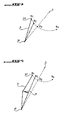
- the flap 4 is thus mounted so that the third axis 62 can be moved between a first position B1 corresponding to the closed shutter, a second position B2 corresponding to the half open shutter, and a third position B4 corresponding to the fully open shutter.
- the displacement between the second and the third positions whatever the direction of movement, makes the third axis pass through a transient position B3.
- the spring 6 of the hatch of the invention is an S-shaped spring having two ends 63, 64.
- the end 63 is disposed inside the hatch on a support 21 shown in Figure 5 or mounted on a support 22 shown in Figure 6, and the end 64 is attached to the arm 7 by the third axis 62.
- the shutter 4 When the shutter door is closed, the shutter 4 is held in its closed position, against the return force of the spring 6, by a latch 11 of a locking means 10 cooperating for this purpose with a locking finger 41 disposed on an inner face of the flap 4:
- the locking finger 41 When closing the door, the locking finger 41 is locked by snapping behind the latch 11 and, conversely, to unlock the flap 4, the latch 11 is retracted to release the finger
- the locking means 10 is electrically controlled or, from within the vehicle, by a cable.
- the movement of the flap 4 grants the spring 6 a first state of stress characterized by elastic elongation of the spring.
- the flap 4 To open the shutter completely, the flap 4 must be rotated from the open position to an open position.
- the user of the vehicle grasps the flap 4 and continues the movement that led from the closed position to the half-open position.
- This pursuit of movement moves the axis 62 of the position B2 corresponding to the half-open position of the flap, first to the transient position B3 by subjecting the spring 6 to a stress different from the first one.
- the spring 6 is subjected to an elongation time that the flap 4 is closed, the spring 6 is subjected to compression when one begins to fully open the flap 4. This compression increases until the third axis 62 reaches the position B3 located on the straight line connecting the second axis 61 with the first axis 5. Beyond this position B3, called the transient position because the axis 62 does not stay on this position but continues its movement, the spring 6 expands again until the axis 62 reaches the third position B4 corresponding on the one hand to the open position of the flap 4 and secondly to the second state of stress of the spring 6.
- the Figure 4 shows the evolution of the third axis 62 between the different positions B1 to B4.
- an alternative embodiment would consist in arranging the spring for example above the axis 62 (in the arrangement shown in FIG. 1).
- the spring would be compressed while the shutter is closed and it is lengthened when opening the shutter.
- the spring is subjected to a first state of stress when the flap is closed and the same spring is then subjected to a second state of stress, different from the first at least as regards the nature of the the constraint, but often also with regard to the force of the stress, when the shutter is fully open.
- FIG. 3 represents the evolution of the third axis 62, that is to say its displacement between the first position B1, the second position B2, the transient position B3 and the third position B4, in a schematized manner.
- the positions B1 to B3 are closely related to each other and to the remote position B4.
- the transient position B3 is situated on the straight line connecting the two fixed axes 5 and 61, and on the other hand that the distance between the second axis 61 and the third axis 62 decreases from the position B1 to the position B3 is that it then increases to the position B4.
- Position B3 thus constitutes a point of return for the size or strength of the second constraint before reaching, at the position B4, the second state of constraint which is determined, like the first, by the nature of the constraint and its scale.
- FIG. 4 represents the evolution of the third axis 62, that is to say its displacement between the first position B1, the second position B2, the transient position B3 and the third position B4, schematically for a second mode of realization of the obturator hatch of the invention. Since this second embodiment is, at first glance, very close to the first, the schematic representation passes this time before the representation of the hardware realization.
- the hatch of the invention according to the second embodiment differing from the hatch according to the first embodiment essentially only by an additional piece, the drawings are limited, as to the second embodiment, to the representation of this embodiment. difference.
- the shutter door comprises a spring 6 pivotally mounted about the second axis 61 and attached to the arm 7 of the flap 4 by the third axis 62.
- the arm 7 is pivotally mounted about the axis 5.
- B1 denotes the position of the axis 62 when the flap 4 is in the open position. So far, the second embodiment corresponds to the first.
- FIG. 4 shows, however, that the spring 6 is folded when the shutter 4 is in the closed position of the hatch and the third axis 62 is in the position B1, which is not the case in the arrangement of the first embodiment. .
- the second embodiment differs from the first by the presence of a rib 71 on the arm 7, the rib being disposed on the rear face of the arm 7 and facing the support 21 or 22 of the spring 6.
- the rib 71 advances the corresponding face of the arm 7 by a sufficient measure to grant the spring 6 a transverse stress indicated on 4 by an arrow and the reference number 71 of the rib, this transverse stress leading to the folding of the spring 6.
- the spring 6 relaxes while straightening while the axis 62 advances to the B2 position. And the flap 4 is then in the half-open position, when the transverse stress is canceled and the axis 62 advanced to the B2 position.
- the second embodiment thus differs from the first embodiment in that the first constraint is an additional constraint, independent of the second.
- the first constraint is therefore not opposite in nature to the second constraint, as in the first mode.
- FIGs 5 to 8, and more particularly Figures 7 and 8, show the elements of the shutter door according to the second embodiment of the invention.
- FIGS. 5 and 6 respectively show the support 21 and the support 22 for the end 63 of the spring 6.
- the support 21, which is advantageously used in pairs, is provided with an excavation 24 forming a support for the end 63 of the 6.
- the support 21 is simple to perform, especially when it comes to forming the circumferential wall 2 of the housing 1 by molding in one piece with the two supports 21. Because the support 21 lends only one support to the spring 6, the spring 6 is mounted only on the side of its end 64 on the arm 7.
- the support 22 makes it possible to mount the spring 6 by its two ends 63 and 64, by presenting an orifice 23 in which the end 63 of the spring 6 can be introduced.
- the support 22 is advantageously used in pairs.
- the supports 21 and 22 can also be used for the hatch according to the first embodiment.
- FIG. 7 shows the rear face of the arm 7. More particularly, two fins 72 are shown, each of which is provided with an orifice 73 intended to receive the end 64 of the spring 6.
- the rear face of the arm 7 is also provided with the rib 71 described above.
- Figure 8 shows the effect obtained by means of the rib 71 when the flap 4 is in the closed position.
Landscapes
- Engineering & Computer Science (AREA)
- Transportation (AREA)
- Sustainable Energy (AREA)
- Chemical & Material Sciences (AREA)
- Combustion & Propulsion (AREA)
- Life Sciences & Earth Sciences (AREA)
- Mechanical Engineering (AREA)
- Sustainable Development (AREA)
- Closing And Opening Devices For Wings, And Checks For Wings (AREA)
- Lock And Its Accessories (AREA)
- Motor Or Generator Frames (AREA)
- Operating, Guiding And Securing Of Roll- Type Closing Members (AREA)
- Rear-View Mirror Devices That Are Mounted On The Exterior Of The Vehicle (AREA)
- Superstructure Of Vehicle (AREA)
- Cooling, Air Intake And Gas Exhaust, And Fuel Tank Arrangements In Propulsion Units (AREA)
Claims (16)
- Verschlussklappe für eine Karosserie eines Kraftfahrzeugs, wobei die Klappe einen Verschlussladen (4) umfasst, der schwenkbar um eine erste starre Achse (5) montiert ist, und ein Rückholmittel (6), das auf den Laden (4) wirkt,
dadurch gekennzeichnet, dass
das Rückholmittel (6) schwenkbar um eine zweite starre Achse (61) montiert und mit den Laden (4) durch eine dritte bewegliche Achse (62) verbunden ist, so dass
das Rückholmittel (6) zwischen mindestens drei verschiedenen Stellungen (B1, B2, B3) schwenkbar ist, nämlich
einer ersten Stellung (B1), die einem ersten Beanspruchungszustand des Rückholmittels (6) und einer geschlossenen Stellung des Verschlussladens (4) entspricht, wobei sich die dritte Achse (62) an einer Seite einer geraden Linie befindet, welche die erste Achse (5) mit der zweiten Achse (61) verbindet,
einer zweiten Stellung (B2), die einem neutralen Beanspruchungszustand des Rückholmittels (6) und einer halb geöffneten Stellung des Verschlussladens (4) entspricht, und
einer dritten Stellung (B4), die einem zweiten Beanspruchungszustand des Rückholmittels (6) entspricht, der sich vom ersten unterscheidet, und einer geöffneten Stellung des Verschlussladens (4), wobei sich die dritte Achse (62) an der anderen Seite der geraden Linie befindet, welche die erste Achse (5) mit der zweiten Achse (61) verbindet. - Klappe nach Anspruch 1, dadurch gekennzeichnet, dass das Rückholmittel (6) eine Feder ist.
- Klappe nach Anspruch 1 oder 2, dadurch gekennzeichnet, dass das Rückholmittel (6) eine Feder ist, die derart gestaltet ist, um Verdrehungs- und Kompressionsbeanspruchungen standzuhalten.
- Klappe nach Anspruch 1 oder 2, dadurch gekennzeichnet, dass das Rückholmittel (6) eine Feder ist, die derart gestaltet ist, um Dehnungs- und Kompressionsbeanspruchungen standzuhalten.
- Klappe nach einem der Ansprüche 1 bis 4, dadurch gekennzeichnet, dass das Rückholmittel (6) eine S-förmige Feder ist.
- Klappe nach einem der Ansprüche 1 bis 5, dadurch gekennzeichnet, dass das Rückholmittel (6) eine Spiralfeder ist.
- Klappe nach einem der Ansprüche 1 bis 6, dadurch gekennzeichnet, dass sie ein Verriegelungselement (20) umfasst, das zum Verriegeln des Verschlussladens (4) bestimmt ist, wenn sich dieser in geschlossener Stellung befindet.
- Klappe nach Anspruch 7, dadurch gekennzeichnet, dass das Verriegelungselement (10) ein aus der Entfernung bedienbares Mittel ist.
- Klappe nach Anspruch 7, dadurch gekennzeichnet, dass das Verriegelungselement (10) ein vom Innenraum des Fahrzeugs bedienbares Mittel ist.
- Klappe nach einem der Ansprüche 1 bis 9, dadurch gekennzeichnet, dass sie ein Gehäuse (1) mit einer Umfangswand (2) mit einem Halter (21, 22) umfasst, der dazu bestimmt ist, eines (63) der zwei gegenüberliegenden Enden (63, 64) des Rückholmittels (6) aufzunehmen, wobei das andere Ende (64) des Rückholmittels (6) am Verschlussladen (4) befestigt ist.
- Klappe nach Anspruch 10, dadurch gekennzeichnet, dass der Halter (21) eine Abstützung für das entsprechende Ende (63) des Rückholmittels (6) bildet und für dieses Ende (63) ein Lager bildet, welches die zweite Schwenkachse (61) des Rückholmittels (6) umfasst.
- Klappe nach Anspruch 10, dadurch gekennzeichnet, dass der Halter (22) mit einer Bohrung (23) versehen ist, die dazu bestimmt ist, das entsprechende Ende (63) des Rückholmittels (6) aufzunehmen und für dieses Ende (63) ein Lager zu bilden, welches die zweite Schwenkachse (61) des Rückholmittels (6) umfasst.
- Klappe nach einem der Ansprüche 1 bis 12, dadurch gekennzeichnet, dass sie einen Arm (7) umfasst, der ein erstes, mit dem Verschlussladen (4) verbundenes Ende (8) und ein zweites, mit der ersten Schwenkachse (5) des Verschlussladens (4) verbundenes Ende (9) hat.
- Klappe nach Anspruch 13, dadurch gekennzeichnet, dass der Arm (7) mit mindestens einem Flügel (72) ausgestattet ist, der eine Bohrung (73) umfasst, die dazu bestimmt ist, das entsprechende Ende (64) des Rückholmittels (6) aufzunehmen und die dritte Schwenkachse (62) des Rückholmittels (6) zu bilden.
- Klappe nach Anspruch 13 oder 14, dadurch gekennzeichnet, dass der Arm (7) mit einer Rippe (71) ausgestattet ist, die dazu bestimmt ist, auf das Rückholmittel (6) eine Verdrehungsbeanspruchung auszuüben.
- Kraftfahrzeug mit einer Karosserie, dadurch gekennzeichnet, dass es eine Klappe nach einem der Ansprüche 1 bis 15 umfasst.
Applications Claiming Priority (2)
| Application Number | Priority Date | Filing Date | Title |
|---|---|---|---|
| FR0406410A FR2871431B1 (fr) | 2004-06-14 | 2004-06-14 | Trappe obturatrice pour une carrosserie d'un vehicule automobile et vehicule automobile comportant une telle trappe |
| FR0406410 | 2004-06-14 |
Publications (2)
| Publication Number | Publication Date |
|---|---|
| EP1607261A1 EP1607261A1 (de) | 2005-12-21 |
| EP1607261B1 true EP1607261B1 (de) | 2007-01-03 |
Family
ID=34945632
Family Applications (1)
| Application Number | Title | Priority Date | Filing Date |
|---|---|---|---|
| EP05290974A Expired - Lifetime EP1607261B1 (de) | 2004-06-14 | 2005-05-04 | Abdeckklappe für eine Kraftfahrzeugkarrosserie und Kraftfahrzeug mit einer derartigen Abdeckklappe |
Country Status (6)
| Country | Link |
|---|---|
| EP (1) | EP1607261B1 (de) |
| AT (1) | ATE350235T1 (de) |
| DE (1) | DE602005000403T2 (de) |
| ES (1) | ES2280073T3 (de) |
| FR (1) | FR2871431B1 (de) |
| PT (1) | PT1607261E (de) |
Families Citing this family (6)
| Publication number | Priority date | Publication date | Assignee | Title |
|---|---|---|---|---|
| DE102007035492B4 (de) * | 2007-07-28 | 2017-02-16 | Volkswagen Ag | Klappenanordnung |
| DE102008047464A1 (de) * | 2008-09-17 | 2010-04-15 | Dr.Ing.H.C.F.Porsche Aktiengesellschaft | Tankklappenmodul |
| JP7134580B2 (ja) * | 2019-02-07 | 2022-09-12 | 株式会社Fts | 給油口蓋の取付構造 |
| JP7518003B2 (ja) * | 2021-01-12 | 2024-07-17 | 株式会社アルファ | リッド装置 |
| EP4201724B1 (de) * | 2021-12-22 | 2024-04-03 | Valmet Automotive Oy | Fahrzeug mit einer bewegbaren klappe |
| DE102023128340A1 (de) * | 2023-10-17 | 2025-04-17 | Bos Gmbh & Co. Kg | Tankklappensystem für ein Kraftfahrzeug |
Family Cites Families (5)
| Publication number | Priority date | Publication date | Assignee | Title |
|---|---|---|---|---|
| DE3212689A1 (de) | 1982-04-05 | 1983-10-06 | Steffen Kammler | Verschluss fuer den fuellstutzen des kraftstoffbehaelters von kraftfahrzeugen |
| US4527825A (en) * | 1983-11-17 | 1985-07-09 | General Motors Corporation | Fuel filler door with dual hinge |
| DE19616315A1 (de) | 1996-04-24 | 1997-10-30 | Mittelhaeuser Bernhard | Tankklappe für Kraftfahrzeuge |
| DE29608315U1 (de) | 1996-05-08 | 1997-09-04 | Ed. Scharwächter GmbH + Co KG, 42855 Remscheid | Tankklappe mit integrierter Aufspringmechanik |
| DE19827194B4 (de) * | 1998-06-18 | 2012-06-06 | Volkswagen Ag | Verschlußklappe für eine Tankmulde eines Kraftfahrzeugs |
-
2004
- 2004-06-14 FR FR0406410A patent/FR2871431B1/fr not_active Expired - Fee Related
-
2005
- 2005-05-04 PT PT05290974T patent/PT1607261E/pt unknown
- 2005-05-04 AT AT05290974T patent/ATE350235T1/de not_active IP Right Cessation
- 2005-05-04 EP EP05290974A patent/EP1607261B1/de not_active Expired - Lifetime
- 2005-05-04 DE DE602005000403T patent/DE602005000403T2/de not_active Expired - Lifetime
- 2005-05-04 ES ES05290974T patent/ES2280073T3/es not_active Expired - Lifetime
Also Published As
| Publication number | Publication date |
|---|---|
| FR2871431A1 (fr) | 2005-12-16 |
| DE602005000403T2 (de) | 2007-11-08 |
| ATE350235T1 (de) | 2007-01-15 |
| PT1607261E (pt) | 2007-04-30 |
| FR2871431B1 (fr) | 2006-09-22 |
| EP1607261A1 (de) | 2005-12-21 |
| ES2280073T3 (es) | 2007-09-01 |
| DE602005000403D1 (de) | 2007-02-15 |
Similar Documents
| Publication | Publication Date | Title |
|---|---|---|
| EP3404176B1 (de) | Vorrichtung zum entriegeln eines türschlosses | |
| FR2513298A1 (fr) | Dispositif pour manoeuvrer des serrures de portiere d'un vehicule automobile | |
| WO2018210903A1 (fr) | Commande de poignée affleurante | |
| FR3110623A1 (fr) | Dispositif d’accès de secours d’ouvrant de véhicule à bras de déploiement rotatif | |
| FR2962086A1 (fr) | Dispositif de rangement pour vehicule automobile comprenant une assistance a l'ouverture | |
| EP1607261B1 (de) | Abdeckklappe für eine Kraftfahrzeugkarrosserie und Kraftfahrzeug mit einer derartigen Abdeckklappe | |
| EP1586726A1 (de) | Mechanismus zum Öffnen und Schliessen einer Kraftfahrzeugtür | |
| EP1655175B1 (de) | Gepäckraumabdeckung mit achsenloser Montage an der Verkleidung eines Kraftfahrzeugs | |
| FR2958962A1 (fr) | Commande d'ouverture interieure d'un ouvrant de vehicule automobile et vehicule automobile equipee d'une telle commande. | |
| FR2937071A1 (fr) | Serrure de capot de vehicule automobile | |
| EP3042014B1 (de) | Schloss für die tür eines kraftfahrzeuges | |
| EP4177425A1 (de) | Externes öffnungssteuergerät für eine kraftfahrzeugöffnung | |
| EP1939379A1 (de) | Aussenvorrichtung zur Steuerung eines Öffnungsflügels eines Fahrzeugs | |
| EP4276265A1 (de) | Schlossanordnung für die motorhaube eines kraftfahrzeugs | |
| FR2963944A1 (fr) | Ensemble comprenant une commande d'ouverture interieure d'un ouvrant de vehicule automobile et des elements d'actionnement permettant de deverrouiller une serrure et d'ouvrir ledit ouvrant | |
| EP0872371B1 (de) | Einfüllvorrichtung für einen Kraftstofftank eines Kraftfahrzeuges mit Verriegelung des Tankverschlusses | |
| FR2908441A1 (fr) | Dispositif de commande d'ouverture d'un ouvrant pour un vehicule automobile | |
| EP3816378B1 (de) | Schloss für öffnungsflügel eines kraftfahrzeugs | |
| EP1151880A1 (de) | Umstellbare Tür für Motorfahrzeug | |
| FR3107295A1 (fr) | Dispositif de verrouillage pour une pièce mobile d’un véhicule | |
| FR2946380A1 (fr) | Charniere a deux axes de pivotement pour ouvrant de vehicule notamment de vehicule automobile et ouvrant equipe d'une telle charniere. | |
| FR2816978A1 (fr) | Systeme de guidage pour ouvrant de vehicule automobile | |
| EP4433678A1 (de) | Riegelanordnung für einen öffnungsfähigen karosserieabschnitt eines kraftfahrzeugs | |
| FR2521744A1 (fr) | Levier de commande perfectionne | |
| WO2024261441A1 (fr) | Dispositif de verrouillage pour le capot d'un véhicule automobile |
Legal Events
| Date | Code | Title | Description |
|---|---|---|---|
| PUAI | Public reference made under article 153(3) epc to a published international application that has entered the european phase |
Free format text: ORIGINAL CODE: 0009012 |
|
| AK | Designated contracting states |
Kind code of ref document: A1 Designated state(s): AT BE BG CH CY CZ DE DK EE ES FI FR GB GR HU IE IS IT LI LT LU MC NL PL PT RO SE SI SK TR |
|
| AX | Request for extension of the european patent |
Extension state: AL BA HR LV MK YU |
|
| 17P | Request for examination filed |
Effective date: 20060329 |
|
| GRAP | Despatch of communication of intention to grant a patent |
Free format text: ORIGINAL CODE: EPIDOSNIGR1 |
|
| AKX | Designation fees paid |
Designated state(s): AT BE BG CH CY CZ DE DK EE ES FI FR GB GR HU IE IS IT LI LT LU MC NL PL PT RO SE SI SK TR |
|
| GRAS | Grant fee paid |
Free format text: ORIGINAL CODE: EPIDOSNIGR3 |
|
| GRAA | (expected) grant |
Free format text: ORIGINAL CODE: 0009210 |
|
| AK | Designated contracting states |
Kind code of ref document: B1 Designated state(s): AT BE BG CH CY CZ DE DK EE ES FI FR GB GR HU IE IS IT LI LT LU MC NL PL PT RO SE SI SK TR |
|
| PG25 | Lapsed in a contracting state [announced via postgrant information from national office to epo] |
Ref country code: SI Free format text: LAPSE BECAUSE OF FAILURE TO SUBMIT A TRANSLATION OF THE DESCRIPTION OR TO PAY THE FEE WITHIN THE PRESCRIBED TIME-LIMIT Effective date: 20070103 Ref country code: NL Free format text: LAPSE BECAUSE OF FAILURE TO SUBMIT A TRANSLATION OF THE DESCRIPTION OR TO PAY THE FEE WITHIN THE PRESCRIBED TIME-LIMIT Effective date: 20070103 Ref country code: IE Free format text: LAPSE BECAUSE OF FAILURE TO SUBMIT A TRANSLATION OF THE DESCRIPTION OR TO PAY THE FEE WITHIN THE PRESCRIBED TIME-LIMIT Effective date: 20070103 Ref country code: AT Free format text: LAPSE BECAUSE OF FAILURE TO SUBMIT A TRANSLATION OF THE DESCRIPTION OR TO PAY THE FEE WITHIN THE PRESCRIBED TIME-LIMIT Effective date: 20070103 Ref country code: DK Free format text: LAPSE BECAUSE OF FAILURE TO SUBMIT A TRANSLATION OF THE DESCRIPTION OR TO PAY THE FEE WITHIN THE PRESCRIBED TIME-LIMIT Effective date: 20070103 Ref country code: PL Free format text: LAPSE BECAUSE OF FAILURE TO SUBMIT A TRANSLATION OF THE DESCRIPTION OR TO PAY THE FEE WITHIN THE PRESCRIBED TIME-LIMIT Effective date: 20070103 Ref country code: FI Free format text: LAPSE BECAUSE OF FAILURE TO SUBMIT A TRANSLATION OF THE DESCRIPTION OR TO PAY THE FEE WITHIN THE PRESCRIBED TIME-LIMIT Effective date: 20070103 |
|
| REG | Reference to a national code |
Ref country code: GB Ref legal event code: FG4D Free format text: NOT ENGLISH |
|
| REF | Corresponds to: |
Ref document number: 602005000403 Country of ref document: DE Date of ref document: 20070215 Kind code of ref document: P |
|
| REG | Reference to a national code |
Ref country code: IE Ref legal event code: FG4D Free format text: LANGUAGE OF EP DOCUMENT: FRENCH |
|
| PG25 | Lapsed in a contracting state [announced via postgrant information from national office to epo] |
Ref country code: BG Free format text: LAPSE BECAUSE OF FAILURE TO SUBMIT A TRANSLATION OF THE DESCRIPTION OR TO PAY THE FEE WITHIN THE PRESCRIBED TIME-LIMIT Effective date: 20070403 Ref country code: SE Free format text: LAPSE BECAUSE OF FAILURE TO SUBMIT A TRANSLATION OF THE DESCRIPTION OR TO PAY THE FEE WITHIN THE PRESCRIBED TIME-LIMIT Effective date: 20070403 |
|
| REG | Reference to a national code |
Ref country code: PT Ref legal event code: SC4A Free format text: AVAILABILITY OF NATIONAL TRANSLATION Effective date: 20070327 |
|
| PG25 | Lapsed in a contracting state [announced via postgrant information from national office to epo] |
Ref country code: IS Free format text: LAPSE BECAUSE OF FAILURE TO SUBMIT A TRANSLATION OF THE DESCRIPTION OR TO PAY THE FEE WITHIN THE PRESCRIBED TIME-LIMIT Effective date: 20070503 |
|
| NLV1 | Nl: lapsed or annulled due to failure to fulfill the requirements of art. 29p and 29m of the patents act | ||
| REG | Reference to a national code |
Ref country code: IE Ref legal event code: FD4D |
|
| REG | Reference to a national code |
Ref country code: ES Ref legal event code: FG2A Ref document number: 2280073 Country of ref document: ES Kind code of ref document: T3 |
|
| PLBE | No opposition filed within time limit |
Free format text: ORIGINAL CODE: 0009261 |
|
| STAA | Information on the status of an ep patent application or granted ep patent |
Free format text: STATUS: NO OPPOSITION FILED WITHIN TIME LIMIT |
|
| 26N | No opposition filed |
Effective date: 20071005 |
|
| BERE | Be: lapsed |
Owner name: PEUGEOT CITROEN AUTOMOBILES S.A. Effective date: 20070531 |
|
| PG25 | Lapsed in a contracting state [announced via postgrant information from national office to epo] |
Ref country code: CZ Free format text: LAPSE BECAUSE OF FAILURE TO SUBMIT A TRANSLATION OF THE DESCRIPTION OR TO PAY THE FEE WITHIN THE PRESCRIBED TIME-LIMIT Effective date: 20070103 Ref country code: RO Free format text: LAPSE BECAUSE OF FAILURE TO SUBMIT A TRANSLATION OF THE DESCRIPTION OR TO PAY THE FEE WITHIN THE PRESCRIBED TIME-LIMIT Effective date: 20070103 |
|
| PG25 | Lapsed in a contracting state [announced via postgrant information from national office to epo] |
Ref country code: MC Free format text: LAPSE BECAUSE OF NON-PAYMENT OF DUE FEES Effective date: 20070531 |
|
| PG25 | Lapsed in a contracting state [announced via postgrant information from national office to epo] |
Ref country code: BE Free format text: LAPSE BECAUSE OF NON-PAYMENT OF DUE FEES Effective date: 20070531 Ref country code: LT Free format text: LAPSE BECAUSE OF FAILURE TO SUBMIT A TRANSLATION OF THE DESCRIPTION OR TO PAY THE FEE WITHIN THE PRESCRIBED TIME-LIMIT Effective date: 20070103 |
|
| REG | Reference to a national code |
Ref country code: GB Ref legal event code: 746 Effective date: 20080329 |
|
| PG25 | Lapsed in a contracting state [announced via postgrant information from national office to epo] |
Ref country code: GR Free format text: LAPSE BECAUSE OF FAILURE TO SUBMIT A TRANSLATION OF THE DESCRIPTION OR TO PAY THE FEE WITHIN THE PRESCRIBED TIME-LIMIT Effective date: 20070404 |
|
| PG25 | Lapsed in a contracting state [announced via postgrant information from national office to epo] |
Ref country code: EE Free format text: LAPSE BECAUSE OF FAILURE TO SUBMIT A TRANSLATION OF THE DESCRIPTION OR TO PAY THE FEE WITHIN THE PRESCRIBED TIME-LIMIT Effective date: 20070103 |
|
| PG25 | Lapsed in a contracting state [announced via postgrant information from national office to epo] |
Ref country code: CY Free format text: LAPSE BECAUSE OF FAILURE TO SUBMIT A TRANSLATION OF THE DESCRIPTION OR TO PAY THE FEE WITHIN THE PRESCRIBED TIME-LIMIT Effective date: 20070103 |
|
| PG25 | Lapsed in a contracting state [announced via postgrant information from national office to epo] |
Ref country code: LU Free format text: LAPSE BECAUSE OF NON-PAYMENT OF DUE FEES Effective date: 20070504 |
|
| PG25 | Lapsed in a contracting state [announced via postgrant information from national office to epo] |
Ref country code: HU Free format text: LAPSE BECAUSE OF FAILURE TO SUBMIT A TRANSLATION OF THE DESCRIPTION OR TO PAY THE FEE WITHIN THE PRESCRIBED TIME-LIMIT Effective date: 20070704 Ref country code: TR Free format text: LAPSE BECAUSE OF FAILURE TO SUBMIT A TRANSLATION OF THE DESCRIPTION OR TO PAY THE FEE WITHIN THE PRESCRIBED TIME-LIMIT Effective date: 20070103 |
|
| REG | Reference to a national code |
Ref country code: CH Ref legal event code: PL |
|
| PG25 | Lapsed in a contracting state [announced via postgrant information from national office to epo] |
Ref country code: LI Free format text: LAPSE BECAUSE OF NON-PAYMENT OF DUE FEES Effective date: 20090531 Ref country code: CH Free format text: LAPSE BECAUSE OF NON-PAYMENT OF DUE FEES Effective date: 20090531 |
|
| PGFP | Annual fee paid to national office [announced via postgrant information from national office to epo] |
Ref country code: ES Payment date: 20100426 Year of fee payment: 6 |
|
| PGFP | Annual fee paid to national office [announced via postgrant information from national office to epo] |
Ref country code: IT Payment date: 20100504 Year of fee payment: 6 |
|
| PG25 | Lapsed in a contracting state [announced via postgrant information from national office to epo] |
Ref country code: IT Free format text: LAPSE BECAUSE OF NON-PAYMENT OF DUE FEES Effective date: 20110504 |
|
| REG | Reference to a national code |
Ref country code: ES Ref legal event code: FD2A Effective date: 20120717 |
|
| PG25 | Lapsed in a contracting state [announced via postgrant information from national office to epo] |
Ref country code: ES Free format text: LAPSE BECAUSE OF NON-PAYMENT OF DUE FEES Effective date: 20110505 |
|
| PGFP | Annual fee paid to national office [announced via postgrant information from national office to epo] |
Ref country code: GB Payment date: 20120423 Year of fee payment: 8 |
|
| GBPC | Gb: european patent ceased through non-payment of renewal fee |
Effective date: 20130504 |
|
| PG25 | Lapsed in a contracting state [announced via postgrant information from national office to epo] |
Ref country code: GB Free format text: LAPSE BECAUSE OF NON-PAYMENT OF DUE FEES Effective date: 20130504 |
|
| REG | Reference to a national code |
Ref country code: FR Ref legal event code: PLFP Year of fee payment: 12 |
|
| PGFP | Annual fee paid to national office [announced via postgrant information from national office to epo] |
Ref country code: DE Payment date: 20160421 Year of fee payment: 12 |
|
| PGFP | Annual fee paid to national office [announced via postgrant information from national office to epo] |
Ref country code: SK Payment date: 20160421 Year of fee payment: 12 |
|
| REG | Reference to a national code |
Ref country code: FR Ref legal event code: PLFP Year of fee payment: 13 |
|
| REG | Reference to a national code |
Ref country code: DE Ref legal event code: R119 Ref document number: 602005000403 Country of ref document: DE |
|
| PG25 | Lapsed in a contracting state [announced via postgrant information from national office to epo] |
Ref country code: SK Free format text: LAPSE BECAUSE OF NON-PAYMENT OF DUE FEES Effective date: 20170504 |
|
| REG | Reference to a national code |
Ref country code: SK Ref legal event code: MM4A Ref document number: E 1693 Country of ref document: SK Effective date: 20170504 |
|
| REG | Reference to a national code |
Ref country code: FR Ref legal event code: PLFP Year of fee payment: 14 |
|
| PG25 | Lapsed in a contracting state [announced via postgrant information from national office to epo] |
Ref country code: DE Free format text: LAPSE BECAUSE OF NON-PAYMENT OF DUE FEES Effective date: 20171201 |
|
| REG | Reference to a national code |
Ref country code: FR Ref legal event code: CA Effective date: 20180312 Ref country code: FR Ref legal event code: CD Owner name: PEUGEOT CITROEN AUTOMOBILES SA, FR Effective date: 20180312 |
|
| PGFP | Annual fee paid to national office [announced via postgrant information from national office to epo] |
Ref country code: PT Payment date: 20180502 Year of fee payment: 14 |
|
| PGFP | Annual fee paid to national office [announced via postgrant information from national office to epo] |
Ref country code: FR Payment date: 20180423 Year of fee payment: 14 |
|
| PG25 | Lapsed in a contracting state [announced via postgrant information from national office to epo] |
Ref country code: PT Free format text: LAPSE BECAUSE OF NON-PAYMENT OF DUE FEES Effective date: 20191104 |
|
| PG25 | Lapsed in a contracting state [announced via postgrant information from national office to epo] |
Ref country code: FR Free format text: LAPSE BECAUSE OF NON-PAYMENT OF DUE FEES Effective date: 20190531 |