EP1607261B1 - Trappe obturatrice pour une carrosserie d'un véhicule automobile et véhicule automobile comportant une telle trappe - Google Patents
Trappe obturatrice pour une carrosserie d'un véhicule automobile et véhicule automobile comportant une telle trappe Download PDFInfo
- Publication number
- EP1607261B1 EP1607261B1 EP05290974A EP05290974A EP1607261B1 EP 1607261 B1 EP1607261 B1 EP 1607261B1 EP 05290974 A EP05290974 A EP 05290974A EP 05290974 A EP05290974 A EP 05290974A EP 1607261 B1 EP1607261 B1 EP 1607261B1
- Authority
- EP
- European Patent Office
- Prior art keywords
- return means
- axis
- lid according
- flap
- spring
- Prior art date
- Legal status (The legal status is an assumption and is not a legal conclusion. Google has not performed a legal analysis and makes no representation as to the accuracy of the status listed.)
- Expired - Lifetime
Links
- 230000007935 neutral effect Effects 0.000 claims description 3
- 230000006835 compression Effects 0.000 description 7
- 238000007906 compression Methods 0.000 description 7
- 230000001052 transient effect Effects 0.000 description 6
- 238000006073 displacement reaction Methods 0.000 description 3
- 230000000694 effects Effects 0.000 description 3
- 239000002828 fuel tank Substances 0.000 description 3
- 208000031968 Cadaver Diseases 0.000 description 1
- 244000261422 Lysimachia clethroides Species 0.000 description 1
- 238000009412 basement excavation Methods 0.000 description 1
- 230000007423 decrease Effects 0.000 description 1
- 238000002955 isolation Methods 0.000 description 1
- 238000004519 manufacturing process Methods 0.000 description 1
- 238000000465 moulding Methods 0.000 description 1
- 230000000717 retained effect Effects 0.000 description 1
- 239000007787 solid Substances 0.000 description 1
Images


Classifications
-
- B—PERFORMING OPERATIONS; TRANSPORTING
- B60—VEHICLES IN GENERAL
- B60K—ARRANGEMENT OR MOUNTING OF PROPULSION UNITS OR OF TRANSMISSIONS IN VEHICLES; ARRANGEMENT OR MOUNTING OF PLURAL DIVERSE PRIME-MOVERS IN VEHICLES; AUXILIARY DRIVES FOR VEHICLES; INSTRUMENTATION OR DASHBOARDS FOR VEHICLES; ARRANGEMENTS IN CONNECTION WITH COOLING, AIR INTAKE, GAS EXHAUST OR FUEL SUPPLY OF PROPULSION UNITS IN VEHICLES
- B60K15/00—Arrangement in connection with fuel supply of combustion engines or other fuel consuming energy converters, e.g. fuel cells; Mounting or construction of fuel tanks
- B60K15/03—Fuel tanks
- B60K15/04—Tank inlets
- B60K15/05—Inlet covers
-
- B—PERFORMING OPERATIONS; TRANSPORTING
- B60—VEHICLES IN GENERAL
- B60K—ARRANGEMENT OR MOUNTING OF PROPULSION UNITS OR OF TRANSMISSIONS IN VEHICLES; ARRANGEMENT OR MOUNTING OF PLURAL DIVERSE PRIME-MOVERS IN VEHICLES; AUXILIARY DRIVES FOR VEHICLES; INSTRUMENTATION OR DASHBOARDS FOR VEHICLES; ARRANGEMENTS IN CONNECTION WITH COOLING, AIR INTAKE, GAS EXHAUST OR FUEL SUPPLY OF PROPULSION UNITS IN VEHICLES
- B60K15/00—Arrangement in connection with fuel supply of combustion engines or other fuel consuming energy converters, e.g. fuel cells; Mounting or construction of fuel tanks
- B60K15/03—Fuel tanks
- B60K15/04—Tank inlets
- B60K15/05—Inlet covers
- B60K2015/0515—Arrangements for closing or opening of inlet cover
- B60K2015/053—Arrangements for closing or opening of inlet cover with hinged connection to the vehicle body
-
- E—FIXED CONSTRUCTIONS
- E05—LOCKS; KEYS; WINDOW OR DOOR FITTINGS; SAFES
- E05F—DEVICES FOR MOVING WINGS INTO OPEN OR CLOSED POSITION; CHECKS FOR WINGS; WING FITTINGS NOT OTHERWISE PROVIDED FOR, CONCERNED WITH THE FUNCTIONING OF THE WING
- E05F1/00—Closers or openers for wings, not otherwise provided for in this subclass
- E05F1/08—Closers or openers for wings, not otherwise provided for in this subclass spring-actuated, e.g. for horizontally sliding wings
- E05F1/10—Closers or openers for wings, not otherwise provided for in this subclass spring-actuated, e.g. for horizontally sliding wings for swinging wings, e.g. counterbalance
- E05F1/12—Mechanisms in the shape of hinges or pivots, operated by springs
- E05F1/123—Mechanisms in the shape of hinges or pivots, operated by springs with a torsion bar
-
- E—FIXED CONSTRUCTIONS
- E05—LOCKS; KEYS; WINDOW OR DOOR FITTINGS; SAFES
- E05Y—INDEXING SCHEME ASSOCIATED WITH SUBCLASSES E05D AND E05F, RELATING TO CONSTRUCTION ELEMENTS, ELECTRIC CONTROL, POWER SUPPLY, POWER SIGNAL OR TRANSMISSION, USER INTERFACES, MOUNTING OR COUPLING, DETAILS, ACCESSORIES, AUXILIARY OPERATIONS NOT OTHERWISE PROVIDED FOR, APPLICATION THEREOF
- E05Y2900/00—Application of doors, windows, wings or fittings thereof
- E05Y2900/50—Application of doors, windows, wings or fittings thereof for vehicles
- E05Y2900/53—Type of wing
- E05Y2900/534—Fuel lids, charger lids
Definitions
- the invention relates to a shutter door for a body of a motor vehicle and a motor vehicle comprising such a hatch.
- a good number of motor vehicles comprising in the bodywork an opening in which ends, coming from inside the bodywork, a conduit connected to a fuel tank.
- This opening is closed by means of a flap whose shape is adapted to that of the body and which is pivotally mounted about an axis.
- the flap thus mounted can pivot between a first position in which the shutter closes the opening in the body and a second position in which access to the conduit from the fuel tank is free.
- Other motor vehicles including industrial vehicles, are equipped with a hatch for respectively closing and give access to a control of a hydraulic working tool or liftgate.
- the shutter is blocked by a lock when it closes the opening in the body.
- the lock is actuated for example by a cable from inside the vehicle or by an electric actuator control coupled or not to unlock the vehicle doors.
- the shutter itself or the edge of the opening in the bodywork is shaped in one or the other of different ways so that a user of the vehicle can slide at least one finger between the shutter and the edge of the opening the time that the shutter is still in closed position and pull on the flap to pivot it to the open position.
- the hatch comprises a return means, generally a spring, arranged so that the flap, when it has just been unlocked, is brought into an open position making it easier for a user of the vehicle to slide. at least one finger between the flap and the edge of the opening and pull on the flap to pivot in the open position.
- a spring is disposed on the inner face of the flap of a shutter door, close to a hook to be retained. by the bolt of a latch of the hatch the time that the shutter is locked. The spring is supported on the latch and is compressed while the flap is in the closed position. When the flap is unlocked, the spring relaxes and thereby pushes the flap in an open position.
- EP-A-0 803 393 does not disclose means for opening the shutter entirely, except for the fingers of a hand, nor means for keeping the shutter in fully open position.
- the shutter door comprises two different means, one of which is a return means for moving the shutter from the closed position to an open position.
- the second means a crank pin, opens the flap fully and keeps the flap in the open position.
- EP-A-0 806 317 which describes the closest state of the art.
- This hatch includes a spring and a pin in the form of a U, one half of the pin serving as the pivot axis of the hatch and the other half serving as pivot axis offset from the spring.
- All shutter doors can take an open position therefore use several means to move the flap of the hatch of the closed position respectively in the open position and in the open position. These designs cause a significant manufacturing cost and assembly time.
- the object of the invention is to provide a shutter door of simple design and having a reduced number of parts.
- the object of the invention is achieved with a shutter door for a body of a motor vehicle, the hatch comprising a shutter pivotally mounted around a first fixed axis, and a return means acting on the shutter.
- the return means is pivotally mounted about a second fixed axis and connected to the flap by a third axis which is movable, so that the biasing means can rotate between at least three distinct positions, namely a first position corresponding to a first state of stress of the return means and a closed position of the shutter, the third axis being situated on one side of a straight line connecting the first axis to the second axis a second position corresponding to a neutral state of stress of the biasing means and an open position of the shutter, and a third position corresponding to a second state of stress, different from the first, of the biasing means and an open position of the Shutter shutter, the third axis being located on the other side of the straight line connecting the first axis to the second axis.
- the shutter door according to the invention is designed so as to use only one means, in this case a return means, and to arrange it so that the position of the return means in which it is solicited the least or, preferably, not at all, where it is in a neutral state of stress, is the one where the flap is ajar.
- the closed position of the flap is then obtained by giving a first constraint to the biasing means and the fully open position is obtained by giving the biasing means a second constraint, different from the first.
- return means includes indifferently tensile springs, compression springs, torsion springs and any other elastically extensible or compressible means producing a return effect.
- return means includes indifferently tensile springs, compression springs, torsion springs and any other elastically extensible or compressible means producing a return effect.
- the hatch according to the invention can be designed essentially according to three different designs, which are distinguished more particularly by the position, with respect to the flap, of the axis about which the flap pivots.
- the axis is located very close to, or even on, the edge of the shutter, in the manner of the axis of a door hinge.
- the flap is provided with a so-called "gooseneck” arm, which locates the axis at a distance from the flap and causes the flap, when pivoted, to move entirely to the flap. outside of the vehicle body.
- the flap is provided with a short arm attached to and within the periphery of the flap, which shifts the axis inwardly of the flap and part of the flap, when rotated, moves inside and the other part outside the vehicle body.
- the obturator flap of the invention comprises a casing 1 having a circumferential wall 2 essentially corresponding to the opening in the bodywork and a bottom wall 3 delimiting the hatch depth.
- the hatch further comprises a shutter 4 pivotally mounted about a first axis 5 and a spring 6 intended to act on an arcuate arm 7 having a first end 8 integral with the flap 4 and a second end 9 having a housing for the axis 5.
- the spring 6 is pivotally mounted on the circumferential wall 2 by a second axis 61 and on the arm 7 by means of a third axis 62.
- the flap 4 is thus mounted so that the third axis 62 can be moved between a first position B1 corresponding to the closed shutter, a second position B2 corresponding to the half open shutter, and a third position B4 corresponding to the fully open shutter.
- the displacement between the second and the third positions whatever the direction of movement, makes the third axis pass through a transient position B3.
- the spring 6 of the hatch of the invention is an S-shaped spring having two ends 63, 64.
- the end 63 is disposed inside the hatch on a support 21 shown in Figure 5 or mounted on a support 22 shown in Figure 6, and the end 64 is attached to the arm 7 by the third axis 62.
- the shutter 4 When the shutter door is closed, the shutter 4 is held in its closed position, against the return force of the spring 6, by a latch 11 of a locking means 10 cooperating for this purpose with a locking finger 41 disposed on an inner face of the flap 4:
- the locking finger 41 When closing the door, the locking finger 41 is locked by snapping behind the latch 11 and, conversely, to unlock the flap 4, the latch 11 is retracted to release the finger
- the locking means 10 is electrically controlled or, from within the vehicle, by a cable.
- the movement of the flap 4 grants the spring 6 a first state of stress characterized by elastic elongation of the spring.
- the flap 4 To open the shutter completely, the flap 4 must be rotated from the open position to an open position.
- the user of the vehicle grasps the flap 4 and continues the movement that led from the closed position to the half-open position.
- This pursuit of movement moves the axis 62 of the position B2 corresponding to the half-open position of the flap, first to the transient position B3 by subjecting the spring 6 to a stress different from the first one.
- the spring 6 is subjected to an elongation time that the flap 4 is closed, the spring 6 is subjected to compression when one begins to fully open the flap 4. This compression increases until the third axis 62 reaches the position B3 located on the straight line connecting the second axis 61 with the first axis 5. Beyond this position B3, called the transient position because the axis 62 does not stay on this position but continues its movement, the spring 6 expands again until the axis 62 reaches the third position B4 corresponding on the one hand to the open position of the flap 4 and secondly to the second state of stress of the spring 6.
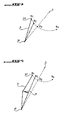
- the Figure 4 shows the evolution of the third axis 62 between the different positions B1 to B4.
- an alternative embodiment would consist in arranging the spring for example above the axis 62 (in the arrangement shown in FIG. 1).
- the spring would be compressed while the shutter is closed and it is lengthened when opening the shutter.
- the spring is subjected to a first state of stress when the flap is closed and the same spring is then subjected to a second state of stress, different from the first at least as regards the nature of the the constraint, but often also with regard to the force of the stress, when the shutter is fully open.
- FIG. 3 represents the evolution of the third axis 62, that is to say its displacement between the first position B1, the second position B2, the transient position B3 and the third position B4, in a schematized manner.
- the positions B1 to B3 are closely related to each other and to the remote position B4.
- the transient position B3 is situated on the straight line connecting the two fixed axes 5 and 61, and on the other hand that the distance between the second axis 61 and the third axis 62 decreases from the position B1 to the position B3 is that it then increases to the position B4.
- Position B3 thus constitutes a point of return for the size or strength of the second constraint before reaching, at the position B4, the second state of constraint which is determined, like the first, by the nature of the constraint and its scale.
- FIG. 4 represents the evolution of the third axis 62, that is to say its displacement between the first position B1, the second position B2, the transient position B3 and the third position B4, schematically for a second mode of realization of the obturator hatch of the invention. Since this second embodiment is, at first glance, very close to the first, the schematic representation passes this time before the representation of the hardware realization.
- the hatch of the invention according to the second embodiment differing from the hatch according to the first embodiment essentially only by an additional piece, the drawings are limited, as to the second embodiment, to the representation of this embodiment. difference.
- the shutter door comprises a spring 6 pivotally mounted about the second axis 61 and attached to the arm 7 of the flap 4 by the third axis 62.
- the arm 7 is pivotally mounted about the axis 5.
- B1 denotes the position of the axis 62 when the flap 4 is in the open position. So far, the second embodiment corresponds to the first.
- FIG. 4 shows, however, that the spring 6 is folded when the shutter 4 is in the closed position of the hatch and the third axis 62 is in the position B1, which is not the case in the arrangement of the first embodiment. .
- the second embodiment differs from the first by the presence of a rib 71 on the arm 7, the rib being disposed on the rear face of the arm 7 and facing the support 21 or 22 of the spring 6.
- the rib 71 advances the corresponding face of the arm 7 by a sufficient measure to grant the spring 6 a transverse stress indicated on 4 by an arrow and the reference number 71 of the rib, this transverse stress leading to the folding of the spring 6.
- the spring 6 relaxes while straightening while the axis 62 advances to the B2 position. And the flap 4 is then in the half-open position, when the transverse stress is canceled and the axis 62 advanced to the B2 position.
- the second embodiment thus differs from the first embodiment in that the first constraint is an additional constraint, independent of the second.
- the first constraint is therefore not opposite in nature to the second constraint, as in the first mode.
- FIGs 5 to 8, and more particularly Figures 7 and 8, show the elements of the shutter door according to the second embodiment of the invention.
- FIGS. 5 and 6 respectively show the support 21 and the support 22 for the end 63 of the spring 6.
- the support 21, which is advantageously used in pairs, is provided with an excavation 24 forming a support for the end 63 of the 6.
- the support 21 is simple to perform, especially when it comes to forming the circumferential wall 2 of the housing 1 by molding in one piece with the two supports 21. Because the support 21 lends only one support to the spring 6, the spring 6 is mounted only on the side of its end 64 on the arm 7.
- the support 22 makes it possible to mount the spring 6 by its two ends 63 and 64, by presenting an orifice 23 in which the end 63 of the spring 6 can be introduced.
- the support 22 is advantageously used in pairs.
- the supports 21 and 22 can also be used for the hatch according to the first embodiment.
- FIG. 7 shows the rear face of the arm 7. More particularly, two fins 72 are shown, each of which is provided with an orifice 73 intended to receive the end 64 of the spring 6.
- the rear face of the arm 7 is also provided with the rib 71 described above.
- Figure 8 shows the effect obtained by means of the rib 71 when the flap 4 is in the closed position.
Landscapes
- Engineering & Computer Science (AREA)
- Transportation (AREA)
- Sustainable Energy (AREA)
- Chemical & Material Sciences (AREA)
- Combustion & Propulsion (AREA)
- Life Sciences & Earth Sciences (AREA)
- Mechanical Engineering (AREA)
- Sustainable Development (AREA)
- Closing And Opening Devices For Wings, And Checks For Wings (AREA)
- Lock And Its Accessories (AREA)
- Superstructure Of Vehicle (AREA)
- Operating, Guiding And Securing Of Roll- Type Closing Members (AREA)
- Motor Or Generator Frames (AREA)
- Rear-View Mirror Devices That Are Mounted On The Exterior Of The Vehicle (AREA)
- Cooling, Air Intake And Gas Exhaust, And Fuel Tank Arrangements In Propulsion Units (AREA)
Description
- L'invention concerne une trappe obturatrice pour une carrosserie d'un véhicule automobile ainsi qu'un véhicule automobile comportant une telle trappe.
- Un bon nombre de véhicules automobiles, notamment les véhicules dits voitures de tourisme, comprennent dans la carrosserie une ouverture dans laquelle aboutit, venant de l'intérieur de la carrosserie, un conduit relié à un réservoir de carburant. Cette ouverture est obturée moyennant un volet dont la forme est adaptée à celle de la carrosserie et qui est monté pivotant autour d'un axe. Le volet ainsi monté peut pivoter entre une première position dans laquelle le volet obture l'ouverture dans la carrosserie et une seconde position dans laquelle l'accès au conduit venant du réservoir de carburant est libre.
- D'autres véhicules automobiles, notamment des véhicules industriels, sont équipés d'une trappe destinée à respectivement obturer et donner accès à une commande d'un outil de travail hydraulique ou d'un hayon élévateur.
- Pour protéger l'accès à ce conduit ou cette commande contre des personnes malveillantes, le volet est bloqué par un verrou lorsqu'il obture l'ouverture dans la carrosserie. Pour débloquer le volet, le verrou est actionné par exemple par un câble venant de l'intérieur du véhicule ou moyennant une commande à actionneur électrique couplée ou non au déverrouillage des portes du véhicule.
- Pour libérer l'accès au conduit venant du réservoir de carburant lorsque le volet est débloqué, plusieurs conceptions de la trappe obturatrice ont déjà été proposée. Selon des conceptions les plus simples, le volet lui-même ou le bord de l'ouverture dans la carrosserie est conformé de l'une ou de l'autre de différentes manières afin qu'un utilisateur du véhicule puisse glisser au moins un doigt entre le volet et le bord de l'ouverture le temps que le volet est encore en position fermée et tirer sur le volet afin de le pivoter en position ouverte.
- Selon une conception améliorée, la trappe comprend un moyen de rappel, en général un ressort, disposé de manière que le volet, lorsqu'il vient d'être déverrouillé, est amené dans une position entrouverte rendant plus facile à un utilisateur du véhicule de glisser au moins un doigt entre le volet et le bord de l'ouverture et de tirer sur le volet afin de le pivoter en position ouverte.
- Une telle conception améliorée est décrite, par exemple, dans le document EP-A-0 803 393. Selon cette conception, un ressort est disposé sur la face intérieure du volet d'une trappe obturatrice, proche d'un crochet destiné à être retenu par le pêne d'un verrou de la trappe le temps que le volet est verrouillé. Le ressort prend appui sur le verrou et est comprimé le temps que le volet est en position fermée. Lorsque le volet est déverrouillé, le ressort se détend et pousse par cela le volet dans une position entrouverte.
- Cependant, le document EP-A-0 803 393 ne décrit pas de moyens permettant d'ouvrir le volet entièrement, à l'exception des doigts d'une main, ni de moyens permettant de maintenir le volet en position entièrement ouverte.
- Selon une conception davantage améliorée, par exemple celle décrite dans le document DE-A-32 12 689, la trappe obturatrice comprend deux moyens différents dont un est un moyen de rappel destiné à mouvoir le volet de la position fermée vers une position entrouverte. Lorsque l'utilisateur du véhicule saisit le volet pour l'ouvrir entièrement, le second moyen, une broche en forme de manivelle, ouvre le volet entièrement et maintient le volet dans la position ouverte.
- Un autre exemple pour une trappe obturatrice davantage améliorée est décrit dans le document EP-A-0 806 317 qui décrit l'état de la technique le plus proche. Cette trappe comprend un ressort et une broche en forme d'un U, une moitié de la broche servant comme axe de pivotement de la trappe et l'autre moitié servant comme axe de pivotement décalé du ressort.
- Toutes les trappes obturatrices pouvant prendre une position entrouverte emploient donc plusieurs moyens pour mouvoir le volet de la trappe de la position fermée respectivement dans la position entrouverte et dans la position ouverte. Ces conceptions occasionnent un coût de fabrication et un temps de montage importants.
- Aussi, le but de l'invention est de proposer une trappe obturatrice de conception simple et ayant un nombre réduit de pièces.
- Le but de l'invention est atteint avec une trappe obturatrice pour une carrosserie d'un véhicule automobile, la trappe comprenant un volet d'obturation monté pivotant autour d'un premier axe fixe, et un moyen de rappel agissant sur le volet.
- Dans la trappe de l'invention, le moyen de rappel est monté pivotant autour d'un deuxième axe fixe et relié au volet par un troisième axe qui, lui, est mobile, de manière que le moyen de rappel puisse pivoter entre au moins trois positions distinctes, à savoir une première position correspondant à un premier état de contrainte du moyen de rappel et une position fermée du volet d'obturation, le troisième axe étant situé d'un côté d'une ligne droite reliant le premier axe au deuxième axe, une deuxième position correspondant à un état neutre de contrainte du moyen de rappel et une position entrouverte du volet d'obturation, et une troisième position correspondant à un deuxième état de contrainte, différent du premier, du moyen de rappel et une position ouverte du volet d'obturation, le troisième axe étant situé de l'autre côté de la ligne droite reliant le premier axe au deuxième axe.
- La trappe obturatrice selon l'invention est conçue de manière à n'utiliser qu'un seul moyen, en l'occurrence un moyen de rappel, et à l'agencer de manière que la position du moyen de rappel dans laquelle il est sollicité le moins ou, de préférence, pas du tout, où il est donc dans un état neutre de contrainte, est celle où le volet est entrouvert. La position fermée du volet est alors obtenue en octroyant une première contrainte au moyen de rappel et la position entièrement ouverte est obtenue en octroyant au moyen de rappel une deuxième contrainte, différente de la première.
- Dans le cadre de la présente invention, le terme « moyen de rappel » englobe indifféremment les ressorts à traction, les ressorts à compression, les ressorts à torsion et tout autre moyen élastiquement extensible ou compressible produisant un effet de rappel. Pour simplifier la description de l'invention, tous les modes de réalisation de l'invention sont décrits avec, comme moyen de rappel, un ressort.
- La trappe selon l'invention peut être conçue essentiellement selon trois conceptions différentes, qui se distinguent plus particulièrement par la position, par rapport au volet, de l'axe autour duquel le volet pivote. Selon la première conception, l'axe est situé très proche de, ou même sur, le bord du volet, à la manière de l'axe d'une charnière de porte.
- Selon la deuxième conception, le volet est pourvu d'un bras dit « col de cygne », ce qui situe l'axe à une certaine distance du volet et fait que le volet, lorsqu'il est pivoté, se meut entièrement à l'extérieur de la carrosserie du véhicule.
- Et selon la troisième conception, le volet est pourvu d'un bras court fixé à l'intérieur du pourtour du volet et à une distance de celui-ci, ce qui décale l'axe vers l'intérieur du volet et fait qu'une partie du volet, lorsqu'il est pivoté, se meut à l'intérieur et l'autre partie à l'extérieur de la carrosserie du véhicule.
- Les modes de réalisation de la trappe de l'invention décrits ci-après relèvent de la deuxième conception.
- La trappe de l'invention a, selon le mode de réalisation choisi, aussi l'une au moins des caractéristiques ci-après, considérées isolément ou selon toute combinaison techniquement possible :
- le moyen de rappel est un ressort ; selon une solution alternative, le moyen de rappel peut également être un corps massif élastiquement déformable ;
- le moyen de rappel est un ressort conformé pour pouvoir être sollicité aussi bien en torsion qu'en compression ;
- le moyen de rappel est un ressort conformé pour pouvoir être sollicité aussi bien en allongement qu'en compression ;
- le moyen de rappel est un ressort en S ;
- le moyen de rappel est un ressort hélicoïdal ;
- la trappe comprend un élément de verrouillage destiné au verrouillage du volet d'obturation, lorsque celui-ci se trouve en position fermée ;
- l'élément de verrouillage est un moyen pouvant être actionné électriquement à distance ;
- l'élément de verrouillage est un moyen pouvant être actionné depuis l'intérieur du véhicule automobile ;
- la trappe comprend un boîtier ayant une paroi circonférentielle avec un support destiné à recevoir une de deux extrémités opposées du moyen de rappel, l'autre extrémité du moyen de rappel étant attachée au volet d'obturation ;
- le support forme un appui pour l'extrémité correspondante du moyen de rappel et constitue pour cette extrémité un palier comportant le deuxième axe de pivotement du moyen de rappel ;
- le support est pourvu d'un perçage destiné à recevoir l'extrémité correspondante du moyen de rappel et à constituer pour cette extrémité un palier comportant le deuxième axe de pivotement du moyen de rappel ;
- la trappe comporte un bras ayant une première extrémité solidaire du volet d'obturation et une seconde extrémité attachée au premier axe de pivotement du volet d'obturation ;
- le bras est pourvu d'au moins une ailette comportant un perçage destiné à recevoir l'extrémité correspondante du moyen de rappel et à constituer le troisième axe de pivotement du moyen de rappel ;
- le bras est pourvu d'une nervure destinée à octroyer une contrainte de torsion au moyen de rappel ;
- lorsque le volet est fermé, il est maintenu dans cet état par un actionneur comportant un pêne et pouvant être commandé par exemple depuis l'habitacle du véhicule.
- D'autres caractéristiques et avantages de la présente invention ressortiront de la description ci-après de deux modes de réalisation de la trappe de l'invention. La description est faite en référence aux dessins dans lesquels :
- les figures 1 et 2 montrent la trappe de l'invention selon un premier mode de réalisation respectivement avec le volet fermé et le volet entrouvert ;
- la figure 3 montre l'évolution du troisième axe de la trappe de l'invention selon le premier mode de réalisation, en fonction de la position du volet ;
- la figure 4 montre l'évolution du troisième axe de la trappe de l'invention selon un second mode de réalisation, en fonction de la position du volet ;
- les figures 5 et 6 montrent deux variantes d'un support pour le moyen de rappel de la trappe de l'invention ; et
- les figures 7 et 8 montrent des détails de la disposition du moyen de rappel de la trappe de l'invention selon le second mode réalisation.
- La trappe obturatrice de l'invention, selon le mode de réalisation représentée sur les figures 1 et 2, comporte un boîtier 1 ayant une paroi circonférentielle 2 correspondant essentiellement à l'ouverture dans la carrosserie et une paroi de fond 3 délimitant la trappe en profondeur.
- La trappe comprend par ailleurs un volet d'obturation 4 monté pivotant autour d'un premier axe 5 et un ressort 6 destiné à agir sur un bras 7 arqué ayant une première extrémité 8 solidaire du volet 4 et une seconde extrémité 9 comportant un logement pour l'axe 5. Le ressort 6 est monté pivotant sur la paroi circonférentielle 2 moyennant un deuxième axe 61 et sur le bras 7 moyennant un troisième axe 62. Le volet 4 est ainsi monté de manière que le troisième axe 62 puisse être déplacé entre une première position B1 correspondant au volet fermé, une deuxième position B2 correspondant au volet entrouvert, et une troisième position B4 correspondant au volet entièrement ouvert. Le déplacement entre la deuxième et la troisième positions, quel qu'en soit le sens de mouvement, fait passer le troisième axe par une position transitoire B3.
- Le ressort 6 de la trappe de l'invention est un ressort en forme d'un S ayant deux extrémités 63, 64. L'extrémité 63 est disposée à l'intérieur de la trappe sur un support 21 représenté sur la figure 5 ou monté sur un support 22 représenté sur la figure 6, et l'extrémité 64 est attachée au bras 7 moyennant le troisième axe 62.
- Lorsque la trappe obturatrice est fermée, le volet 4 est maintenu dans sa position fermée, à l'encontre de la force de rappel du ressort 6, par un loqueteau 11 d'un moyen de verrouillage 10 coopérant à cet effet avec un doigt de verrouillage 41 disposé sur une face intérieure du volet 4 : Lors de la fermeture de la trappe, le doigt de verrouillage 41 est bloqué par encliquetage derrière le loqueteau 11 et, inversement, pour débloquer le volet 4, le loqueteau 11 est rétracté pour libérer le doigt de verrouillage 41. Le moyen de verrouillage 10 est commandé électriquement ou, de l'intérieur du véhicule, par un câble.
- Lors de la fermeture de la trappe de l'invention, le mouvement du volet 4 octroie au ressort 6 un premier état de contrainte caractérisé par un allongement élastique du ressort.
- Lors de l'ouverture de la trappe de l'invention, lorsque le loqueteau 11 vient d'être rétracté et le doigt de verrouillage 41 ainsi libéré, le ressort 6 se détend en reprenant sa longueur ou forme hors contrainte. Cette relaxation du ressort 6 a pour effet que le volet 4 est légèrement pivoté de la position fermée vers une position entrouverte.
- Pour ouvrir la trappe obturatrice entièrement, le volet 4 doit être pivoté de la position entrouverte vers une position ouverte. A cet effet, l'utilisateur du véhicule saisit le volet 4 et le fait poursuivre le mouvement qui l'a conduit de la position fermée jusqu'à la position entrouverte. Cette poursuite du mouvement déplace l'axe 62 de la position B2 correspondant à la position entrouverte du volet, d'abord vers la position transitoire B3 en soumettant le ressort 6 à une contrainte différente de la première.
- En effet, alors que le ressort 6 est soumis à un allongement le temps que le volet 4 est fermé, le ressort 6 est soumis à une compression lorsque l'on commence à ouvrir entièrement le volet 4. Cette compression augmente jusqu'à ce que le troisième axe 62 atteigne la position B3 située sur la droite reliant le deuxième axe 61 avec le premier axe 5. Au delà de cette position B3, appelée position transitoire parce que l'axe 62 ne reste pas sur cette position mais poursuit son mouvement, le ressort 6 se détend à nouveau jusqu'à ce que l'axe 62 atteigne la troisième position B4 correspondant d'une part à la position ouverte du volet 4 et d'autre part au deuxième état de contrainte du ressort 6.
- La position B3 étant relativement proche de la position B2, une impulsion légère de l'utilisateur du véhicule suffit pour amorcer l'ouverture du volet 4. La figure 4 montre l'évolution du troisième axe 62 entre les différentes positions B1 à B4.
- Conformément au principe de la présente invention, une réalisation alternative consisterait à disposer le ressort par exemple au dessus de l'axe 62 (dans la disposition représentée sur la figure 1). Dans ce cas, le ressort serait comprimé le temps que le volet est fermé et il est allongé lors de l'ouverture du volet.
- Quel que soit le mode de réalisation choisi, le ressort est soumis à un premier état de contrainte lorsque le volet est fermé et ce même ressort est soumis ensuite à un deuxième état de contrainte, différent du premier au moins en ce qui concerne la nature de la contrainte, mais souvent aussi en ce qui concerne la force de la contrainte, lorsque le volet est entièrement ouvert.
- En d'autres termes : les déplacements du volet entre les trois positions fermée, entrouverte et entièrement ouverte, quel qu'en soit leur sens de mouvement, sont obtenus moyennant un moyen unique, en l'occurrence un moyen de rappel unique sous la forme du seul ressort 6.
- La figure 3 représente l'évolution du troisième axe 62, c'est-à-dire son déplacement entre la première position B1, la deuxième position B2, la position transitoire B3 et la troisième position B4, de manière schématisée. On y remarque plus particulièrement la proximité des positions B1 à B3 entre elles et la position éloignée B4. De même, on y remarque, d'une part comme indiqué plus haut, que la position transitoire B3 est située sur la ligne droite reliant les deux axes fixes 5 et 61, et d'autre part que la distance entre le deuxième axe 61 et le troisième axe 62 décroît en passant de la position B1 jusqu'à la position B3 est qu'elle augmente ensuite jusqu'à la position B4. La position B3 constitue ainsi un point de retour pour l'envergure ou la force de la deuxième contrainte avant d'atteindre, à la position B4, le deuxième état de contrainte qui est déterminé, comme le premier, par la nature de la contrainte et son envergure.
- La figure 4 représente l'évolution du troisième axe 62, c'est-à-dire son déplacement entre la première position B1, la deuxième position B2, la position transitoire B3 et la troisième position B4, de manière schématisée pour un second mode de réalisation de la trappe obturatrice de l'invention. Puisque ce second mode de réalisation est, à première vue, très proche du premier, la représentation schématique passe cette fois-ci avant la représentation de la réalisation matérielle. De plus, la trappe de l'invention selon le second mode de réalisation ne différant de la trappe selon le premier mode de réalisation essentiellement que par une pièce supplémentaire, les dessins se limitent, quant au second mode de réalisation, à la représentation de cette différence.
- Ainsi, la trappe obturatrice selon le second mode de réalisation comprend un ressort 6 monté pivotant autour du deuxième axe 61 et attaché au bras 7 du volet 4 par le troisième axe 62. Le bras 7 est monté pivotant autour de l'axe 5. Lorsque le volet 4 est en position fermée, le troisième axe 62 est en position B1 et lorsque le volet 4 est en position entièrement ouverte, le troisième axe 62 est en position B4. Et B2 désigne la position de l'axe 62 lorsque le volet 4 est en position entrouverte. Jusqu'ici, le second mode de réalisation correspond au premier.
- La figure 4 montre cependant que le ressort 6 est plié lorsque le volet 4 est en position fermée de la trappe et le troisième axe 62 se trouve dans la position B1, ce qui n'est pas le cas dans la disposition du premier mode de réalisation.
- En effet, le second mode de réalisation diffère du premier par la présence d'une nervure 71 sur le bras 7, la nervure étant disposée sur la face arrière du bras 7 et en regard au support 21 ou 22 du ressort 6. Ainsi, lorsque le volet 4 est poussé vers la position fermée, la nervure 71 devance la face correspondante du bras 7 d'une mesure suffisante pour octroyer au ressort 6 une contrainte transversale indiquée sur la figure 4 par une flèche et le numéro de référence 71 de la nervure, cette contrainte transversale conduisant au pliage du ressort 6.
- Lorsque le volet 4 est en position fermée, le troisième axe 62 est en position B1 et le ressort 6 est donc plié par la nervure 71.
- Lorsque le volet 4 vient d'être déverrouillé, le ressort 6 se détend en se redressant pendant que l'axe 62 avance vers la position B2. Et le volet 4 se trouve alors en position entrouverte, lorsque la contrainte transversale est annulée et l'axe 62 avancé vers la position B2.
- L'ouverture entière de la trappe à partir du volet 4 entrouvert est ensuite obtenue de la même façon qu'avec une trappe selon le premier mode de réalisation.
- Le second mode de réalisation diffère ainsi du premier mode de réalisation par le fait que la première contrainte est une contrainte supplémentaire, indépendante de la seconde. La première contrainte n'est donc pas de nature opposée par rapport à la seconde contrainte, comme dans le premier mode.
- Les figures 5 à 8, et plus particulièrement les figures 7 et 8, montrent les éléments de la trappe obturatrice selon le second mode de réalisation de l'invention.
- Les figures 5 et 6 montrent respectivement le support 21 et le support 22 pour l'extrémité 63 du ressort 6. Le support 21, qui est avantageusement utilisé par paire, est pourvu d'une excavation 24 formant un appui pour l'extrémité 63 du ressort 6. Le support 21 est simple à réaliser, notamment lorsqu'il s'agit de former la paroi circonférentielle 2 du boîtier 1 par moulage en une seule pièce avec les deux supports 21. Du fait que le support 21 ne prête qu'un appui au ressort 6, le ressort 6 n'est monté que du côté de son extrémité 64 sur le bras 7.
- Le support 22, par contre, permet de monter le ressort 6 par ses deux extrémités 63 et 64, en présentant un orifice 23 dans lequel l'extrémité 63 du ressort 6 peut être introduite. Le support 22 est utilisé avantageusement par paire.
- Les supports 21 et 22 peuvent être utilisés également pour la trappe selon le premier mode de réalisation.
- La figure 7 montre la face arrière du bras 7. On y voit plus particulièrement deux ailettes 72 dont chacune est pourvue d'un orifice 73 destiné à recevoir l'extrémité 64 du ressort 6. La face arrière du bras 7 est pourvue par ailleurs de la nervure 71 décrite plus haut.
- La figure 8 montre l'effet obtenu moyennant la nervure 71 lorsque le volet 4 est en position fermée.
Claims (16)
- Trappe obturatrice pour une carrosserie d'un véhicule automobile, la trappe comprenant un volet d'obturation (4) monté pivotant autour d'un premier axe fixe (5) et un moyen de rappel (6) agissant sur le volet (4),
caractérisée en ce que
le moyen de rappel (6) est monté pivotant autour d'un deuxième axe fixe (61) et relié au volet (4) par un troisième axe mobile (62), de manière que
le moyen de rappel (6) puisse pivoter entre au moins trois positions distinctes (B1, B2, B3), à savoir
une première position (B1) correspondant à un premier état de contrainte du moyen de rappel (6) et une position fermée du volet d'obturation (4), le troisième axe (62) étant situé d'un côté d'une ligne droite reliant le premier axe (5) au deuxième axe (61),
une deuxième position (B2) correspondant à un état neutre de contrainte du moyen de rappel (6) et une position entrouverte du volet d'obturation (4), et
une troisième position (B4) correspondant à un deuxième état de contrainte, différent du premier, du moyen de rappel (6) et une position ouverte du volet d'obturation (4), le troisième axe (62) étant situé de l'autre côté de la ligne droite reliant le premier axe (5) au deuxième axe (61). - Trappe selon la revendication 1, caractérisée en ce que le moyen de rappel (6) est un ressort.
- Trappe selon la revendication 1 ou 2, caractérisée en ce que le moyen de rappel (6) est un ressort conformé pour supporter des contraintes en torsion et des contraintes en compression.
- Trappe selon la revendication 1 ou 2, caractérisée en ce que le moyen de rappel (6) est un ressort conformé pour supporter des contraintes en allongement et des contraintes en compression.
- Trappe selon l'une quelconque des revendications 1 à 4, caractérisée en ce que le moyen de rappel (6) est un ressort en S.
- Trappe selon l'une quelconque des revendications 1 à 5, caractérisée en ce que le moyen de rappel (6) est un ressort hélicoïdal.
- Trappe selon l'une quelconque des revendications 1 à 6, caractérisée en ce qu'elle comprend un élément de verrouillage (20) destiné au verrouillage du volet d'obturation (4), lorsque celui-ci se trouve en position fermée.
- Trappe selon la revendication 7, caractérisée en ce que l'élément de verrouillage (10) est un moyen pouvant être actionné à distance.
- Trappe selon la revendication 7, caractérisée en ce que l'élément de verrouillage (10) est un moyen pouvant être actionné depuis l'intérieur du véhicule automobile.
- Trappe selon l'une quelconque des revendications 1 à 9, caractérisée en ce qu'elle comprend un boîtier (1) ayant une paroi circonférentielle (2) avec un support (21, 22) destiné à recevoir une (63) de deux extrémités opposées (63, 64) du moyen de rappel (6), l'autre extrémité (64) du moyen de rappel (6) étant attachée au volet d'obturation (4).
- Trappe selon la revendication 10, caractérisée en ce que le support (21) forme un appui pour l'extrémité correspondante (63) du moyen de rappel (6) et constitue pour cette extrémité (63) un palier comportant le deuxième axe (61) de pivotement du moyen de rappel (6).
- Trappe selon la revendication 10, caractérisée en ce que le support (22) est pourvu d'un perçage (23) destiné à recevoir l'extrémité correspondante (63) du moyen de rappel (6) et à constituer pour cette extrémité (63) un palier comportant le deuxième axe (61) de pivotement du moyen de rappel (6).
- Trappe selon l'une quelconque des revendications 1 à 12, caractérisée en ce qu'elle comporte un bras (7) ayant une première extrémité (8) solidaire du volet d'obturation (4) et une seconde extrémité (9) attachée au premier axe de pivotement (5) du volet d'obturation (4).
- Trappe selon la revendication 13, caractérisée en ce que le bras (7) est pourvu d'au moins une ailette (72) comportant un perçage (73) destiné à recevoir l'extrémité correspondante (64) du moyen de rappel (6) et à constituer le troisième axe (62) de pivotement du moyen de rappel (6).
- Trappe selon la revendication 13 ou 14, caractérisée en ce que le bras (7) est pourvu d'une nervure (71) destinée à octroyer une contrainte de torsion au moyen de rappel (6).
- Véhicule automobile ayant une carrosserie, caractérisé en ce qu'il comprend une trappe selon l'une quelconque des revendications 1 à 15.
Applications Claiming Priority (2)
| Application Number | Priority Date | Filing Date | Title |
|---|---|---|---|
| FR0406410A FR2871431B1 (fr) | 2004-06-14 | 2004-06-14 | Trappe obturatrice pour une carrosserie d'un vehicule automobile et vehicule automobile comportant une telle trappe |
| FR0406410 | 2004-06-14 |
Publications (2)
| Publication Number | Publication Date |
|---|---|
| EP1607261A1 EP1607261A1 (fr) | 2005-12-21 |
| EP1607261B1 true EP1607261B1 (fr) | 2007-01-03 |
Family
ID=34945632
Family Applications (1)
| Application Number | Title | Priority Date | Filing Date |
|---|---|---|---|
| EP05290974A Expired - Lifetime EP1607261B1 (fr) | 2004-06-14 | 2005-05-04 | Trappe obturatrice pour une carrosserie d'un véhicule automobile et véhicule automobile comportant une telle trappe |
Country Status (6)
| Country | Link |
|---|---|
| EP (1) | EP1607261B1 (fr) |
| AT (1) | ATE350235T1 (fr) |
| DE (1) | DE602005000403T2 (fr) |
| ES (1) | ES2280073T3 (fr) |
| FR (1) | FR2871431B1 (fr) |
| PT (1) | PT1607261E (fr) |
Families Citing this family (6)
| Publication number | Priority date | Publication date | Assignee | Title |
|---|---|---|---|---|
| DE102007035492B4 (de) * | 2007-07-28 | 2017-02-16 | Volkswagen Ag | Klappenanordnung |
| DE102008047464A1 (de) * | 2008-09-17 | 2010-04-15 | Dr.Ing.H.C.F.Porsche Aktiengesellschaft | Tankklappenmodul |
| JP7134580B2 (ja) * | 2019-02-07 | 2022-09-12 | 株式会社Fts | 給油口蓋の取付構造 |
| JP7518003B2 (ja) * | 2021-01-12 | 2024-07-17 | 株式会社アルファ | リッド装置 |
| EP4201724B1 (fr) * | 2021-12-22 | 2024-04-03 | Valmet Automotive Oy | Véhicule avec un volet mobile |
| DE102023128340A1 (de) * | 2023-10-17 | 2025-04-17 | Bos Gmbh & Co. Kg | Tankklappensystem für ein Kraftfahrzeug |
Family Cites Families (5)
| Publication number | Priority date | Publication date | Assignee | Title |
|---|---|---|---|---|
| DE3212689A1 (de) | 1982-04-05 | 1983-10-06 | Steffen Kammler | Verschluss fuer den fuellstutzen des kraftstoffbehaelters von kraftfahrzeugen |
| US4527825A (en) * | 1983-11-17 | 1985-07-09 | General Motors Corporation | Fuel filler door with dual hinge |
| DE19616315A1 (de) | 1996-04-24 | 1997-10-30 | Mittelhaeuser Bernhard | Tankklappe für Kraftfahrzeuge |
| DE29608315U1 (de) | 1996-05-08 | 1997-09-04 | Ed. Scharwächter GmbH + Co KG, 42855 Remscheid | Tankklappe mit integrierter Aufspringmechanik |
| DE19827194B4 (de) * | 1998-06-18 | 2012-06-06 | Volkswagen Ag | Verschlußklappe für eine Tankmulde eines Kraftfahrzeugs |
-
2004
- 2004-06-14 FR FR0406410A patent/FR2871431B1/fr not_active Expired - Fee Related
-
2005
- 2005-05-04 PT PT05290974T patent/PT1607261E/pt unknown
- 2005-05-04 DE DE602005000403T patent/DE602005000403T2/de not_active Expired - Lifetime
- 2005-05-04 ES ES05290974T patent/ES2280073T3/es not_active Expired - Lifetime
- 2005-05-04 AT AT05290974T patent/ATE350235T1/de not_active IP Right Cessation
- 2005-05-04 EP EP05290974A patent/EP1607261B1/fr not_active Expired - Lifetime
Also Published As
| Publication number | Publication date |
|---|---|
| PT1607261E (pt) | 2007-04-30 |
| EP1607261A1 (fr) | 2005-12-21 |
| DE602005000403T2 (de) | 2007-11-08 |
| ES2280073T3 (es) | 2007-09-01 |
| DE602005000403D1 (de) | 2007-02-15 |
| ATE350235T1 (de) | 2007-01-15 |
| FR2871431B1 (fr) | 2006-09-22 |
| FR2871431A1 (fr) | 2005-12-16 |
Similar Documents
| Publication | Publication Date | Title |
|---|---|---|
| EP3404176B2 (fr) | Dispositif de déverrouillage d'un serrure de porte | |
| WO2018210903A1 (fr) | Commande de poignée affleurante | |
| FR2976533A1 (fr) | Tiroir et dispositif de compartiment de rangement comportant un tiroir | |
| FR3110623A1 (fr) | Dispositif d’accès de secours d’ouvrant de véhicule à bras de déploiement rotatif | |
| EP1586726B1 (fr) | Mécanisme d'ouverture/fermeture de portière de véhicule automobile | |
| FR2962086A1 (fr) | Dispositif de rangement pour vehicule automobile comprenant une assistance a l'ouverture | |
| EP1655175B1 (fr) | Cache-bagages monte sans axe sur l'ébénisterie d'un véhicule automobile | |
| FR2958962A1 (fr) | Commande d'ouverture interieure d'un ouvrant de vehicule automobile et vehicule automobile equipee d'une telle commande. | |
| FR2937071A1 (fr) | Serrure de capot de vehicule automobile | |
| FR2871431A1 (fr) | Trappe obturatrice pour une carrosserie d'un vehicule automobile et vehicule automobile comportant une telle trappe | |
| EP3042014B1 (fr) | Serrure pour ouvrant de vehicule automobile | |
| EP4177425A1 (fr) | Dispositif de commande d'ouverture extérieure d'un ouvrant de véhicule automobile | |
| EP1939379A1 (fr) | Dispositif de commande extérieur d'un ouvrant d'un véhicule | |
| EP4276265A1 (fr) | Agencement de serrure pour capot de véhicule automobile | |
| FR2963944A1 (fr) | Ensemble comprenant une commande d'ouverture interieure d'un ouvrant de vehicule automobile et des elements d'actionnement permettant de deverrouiller une serrure et d'ouvrir ledit ouvrant | |
| EP0872371B1 (fr) | Dispositif de remplissage d'un réservoir de carburant pour un véhicule automobile comportant des moyens perfectionnés de verrouillage d'un volet d'obturation | |
| FR2908441A1 (fr) | Dispositif de commande d'ouverture d'un ouvrant pour un vehicule automobile | |
| EP3816378B1 (fr) | Serrure pour ouvrant de véhicule automobile | |
| EP1151880A1 (fr) | Porte transformable de véhicule automobile | |
| FR3107295A1 (fr) | Dispositif de verrouillage pour une pièce mobile d’un véhicule | |
| FR2946380A1 (fr) | Charniere a deux axes de pivotement pour ouvrant de vehicule notamment de vehicule automobile et ouvrant equipe d'une telle charniere. | |
| FR2816978A1 (fr) | Systeme de guidage pour ouvrant de vehicule automobile | |
| EP4433678A1 (fr) | Agencement de verrou pour ouvrant de véhicule automobile | |
| FR2521744A1 (fr) | Levier de commande perfectionne | |
| FR3150227A1 (fr) | Dispositif de verrouillage pour le capot d’un véhicule automobile |
Legal Events
| Date | Code | Title | Description |
|---|---|---|---|
| PUAI | Public reference made under article 153(3) epc to a published international application that has entered the european phase |
Free format text: ORIGINAL CODE: 0009012 |
|
| AK | Designated contracting states |
Kind code of ref document: A1 Designated state(s): AT BE BG CH CY CZ DE DK EE ES FI FR GB GR HU IE IS IT LI LT LU MC NL PL PT RO SE SI SK TR |
|
| AX | Request for extension of the european patent |
Extension state: AL BA HR LV MK YU |
|
| 17P | Request for examination filed |
Effective date: 20060329 |
|
| GRAP | Despatch of communication of intention to grant a patent |
Free format text: ORIGINAL CODE: EPIDOSNIGR1 |
|
| AKX | Designation fees paid |
Designated state(s): AT BE BG CH CY CZ DE DK EE ES FI FR GB GR HU IE IS IT LI LT LU MC NL PL PT RO SE SI SK TR |
|
| GRAS | Grant fee paid |
Free format text: ORIGINAL CODE: EPIDOSNIGR3 |
|
| GRAA | (expected) grant |
Free format text: ORIGINAL CODE: 0009210 |
|
| AK | Designated contracting states |
Kind code of ref document: B1 Designated state(s): AT BE BG CH CY CZ DE DK EE ES FI FR GB GR HU IE IS IT LI LT LU MC NL PL PT RO SE SI SK TR |
|
| PG25 | Lapsed in a contracting state [announced via postgrant information from national office to epo] |
Ref country code: SI Free format text: LAPSE BECAUSE OF FAILURE TO SUBMIT A TRANSLATION OF THE DESCRIPTION OR TO PAY THE FEE WITHIN THE PRESCRIBED TIME-LIMIT Effective date: 20070103 Ref country code: NL Free format text: LAPSE BECAUSE OF FAILURE TO SUBMIT A TRANSLATION OF THE DESCRIPTION OR TO PAY THE FEE WITHIN THE PRESCRIBED TIME-LIMIT Effective date: 20070103 Ref country code: IE Free format text: LAPSE BECAUSE OF FAILURE TO SUBMIT A TRANSLATION OF THE DESCRIPTION OR TO PAY THE FEE WITHIN THE PRESCRIBED TIME-LIMIT Effective date: 20070103 Ref country code: AT Free format text: LAPSE BECAUSE OF FAILURE TO SUBMIT A TRANSLATION OF THE DESCRIPTION OR TO PAY THE FEE WITHIN THE PRESCRIBED TIME-LIMIT Effective date: 20070103 Ref country code: DK Free format text: LAPSE BECAUSE OF FAILURE TO SUBMIT A TRANSLATION OF THE DESCRIPTION OR TO PAY THE FEE WITHIN THE PRESCRIBED TIME-LIMIT Effective date: 20070103 Ref country code: PL Free format text: LAPSE BECAUSE OF FAILURE TO SUBMIT A TRANSLATION OF THE DESCRIPTION OR TO PAY THE FEE WITHIN THE PRESCRIBED TIME-LIMIT Effective date: 20070103 Ref country code: FI Free format text: LAPSE BECAUSE OF FAILURE TO SUBMIT A TRANSLATION OF THE DESCRIPTION OR TO PAY THE FEE WITHIN THE PRESCRIBED TIME-LIMIT Effective date: 20070103 |
|
| REG | Reference to a national code |
Ref country code: GB Ref legal event code: FG4D Free format text: NOT ENGLISH |
|
| REF | Corresponds to: |
Ref document number: 602005000403 Country of ref document: DE Date of ref document: 20070215 Kind code of ref document: P |
|
| REG | Reference to a national code |
Ref country code: IE Ref legal event code: FG4D Free format text: LANGUAGE OF EP DOCUMENT: FRENCH |
|
| PG25 | Lapsed in a contracting state [announced via postgrant information from national office to epo] |
Ref country code: BG Free format text: LAPSE BECAUSE OF FAILURE TO SUBMIT A TRANSLATION OF THE DESCRIPTION OR TO PAY THE FEE WITHIN THE PRESCRIBED TIME-LIMIT Effective date: 20070403 Ref country code: SE Free format text: LAPSE BECAUSE OF FAILURE TO SUBMIT A TRANSLATION OF THE DESCRIPTION OR TO PAY THE FEE WITHIN THE PRESCRIBED TIME-LIMIT Effective date: 20070403 |
|
| REG | Reference to a national code |
Ref country code: PT Ref legal event code: SC4A Free format text: AVAILABILITY OF NATIONAL TRANSLATION Effective date: 20070327 |
|
| PG25 | Lapsed in a contracting state [announced via postgrant information from national office to epo] |
Ref country code: IS Free format text: LAPSE BECAUSE OF FAILURE TO SUBMIT A TRANSLATION OF THE DESCRIPTION OR TO PAY THE FEE WITHIN THE PRESCRIBED TIME-LIMIT Effective date: 20070503 |
|
| NLV1 | Nl: lapsed or annulled due to failure to fulfill the requirements of art. 29p and 29m of the patents act | ||
| REG | Reference to a national code |
Ref country code: IE Ref legal event code: FD4D |
|
| REG | Reference to a national code |
Ref country code: ES Ref legal event code: FG2A Ref document number: 2280073 Country of ref document: ES Kind code of ref document: T3 |
|
| PLBE | No opposition filed within time limit |
Free format text: ORIGINAL CODE: 0009261 |
|
| STAA | Information on the status of an ep patent application or granted ep patent |
Free format text: STATUS: NO OPPOSITION FILED WITHIN TIME LIMIT |
|
| 26N | No opposition filed |
Effective date: 20071005 |
|
| BERE | Be: lapsed |
Owner name: PEUGEOT CITROEN AUTOMOBILES S.A. Effective date: 20070531 |
|
| PG25 | Lapsed in a contracting state [announced via postgrant information from national office to epo] |
Ref country code: CZ Free format text: LAPSE BECAUSE OF FAILURE TO SUBMIT A TRANSLATION OF THE DESCRIPTION OR TO PAY THE FEE WITHIN THE PRESCRIBED TIME-LIMIT Effective date: 20070103 Ref country code: RO Free format text: LAPSE BECAUSE OF FAILURE TO SUBMIT A TRANSLATION OF THE DESCRIPTION OR TO PAY THE FEE WITHIN THE PRESCRIBED TIME-LIMIT Effective date: 20070103 |
|
| PG25 | Lapsed in a contracting state [announced via postgrant information from national office to epo] |
Ref country code: MC Free format text: LAPSE BECAUSE OF NON-PAYMENT OF DUE FEES Effective date: 20070531 |
|
| PG25 | Lapsed in a contracting state [announced via postgrant information from national office to epo] |
Ref country code: BE Free format text: LAPSE BECAUSE OF NON-PAYMENT OF DUE FEES Effective date: 20070531 Ref country code: LT Free format text: LAPSE BECAUSE OF FAILURE TO SUBMIT A TRANSLATION OF THE DESCRIPTION OR TO PAY THE FEE WITHIN THE PRESCRIBED TIME-LIMIT Effective date: 20070103 |
|
| REG | Reference to a national code |
Ref country code: GB Ref legal event code: 746 Effective date: 20080329 |
|
| PG25 | Lapsed in a contracting state [announced via postgrant information from national office to epo] |
Ref country code: GR Free format text: LAPSE BECAUSE OF FAILURE TO SUBMIT A TRANSLATION OF THE DESCRIPTION OR TO PAY THE FEE WITHIN THE PRESCRIBED TIME-LIMIT Effective date: 20070404 |
|
| PG25 | Lapsed in a contracting state [announced via postgrant information from national office to epo] |
Ref country code: EE Free format text: LAPSE BECAUSE OF FAILURE TO SUBMIT A TRANSLATION OF THE DESCRIPTION OR TO PAY THE FEE WITHIN THE PRESCRIBED TIME-LIMIT Effective date: 20070103 |
|
| PG25 | Lapsed in a contracting state [announced via postgrant information from national office to epo] |
Ref country code: CY Free format text: LAPSE BECAUSE OF FAILURE TO SUBMIT A TRANSLATION OF THE DESCRIPTION OR TO PAY THE FEE WITHIN THE PRESCRIBED TIME-LIMIT Effective date: 20070103 |
|
| PG25 | Lapsed in a contracting state [announced via postgrant information from national office to epo] |
Ref country code: LU Free format text: LAPSE BECAUSE OF NON-PAYMENT OF DUE FEES Effective date: 20070504 |
|
| PG25 | Lapsed in a contracting state [announced via postgrant information from national office to epo] |
Ref country code: HU Free format text: LAPSE BECAUSE OF FAILURE TO SUBMIT A TRANSLATION OF THE DESCRIPTION OR TO PAY THE FEE WITHIN THE PRESCRIBED TIME-LIMIT Effective date: 20070704 Ref country code: TR Free format text: LAPSE BECAUSE OF FAILURE TO SUBMIT A TRANSLATION OF THE DESCRIPTION OR TO PAY THE FEE WITHIN THE PRESCRIBED TIME-LIMIT Effective date: 20070103 |
|
| REG | Reference to a national code |
Ref country code: CH Ref legal event code: PL |
|
| PG25 | Lapsed in a contracting state [announced via postgrant information from national office to epo] |
Ref country code: LI Free format text: LAPSE BECAUSE OF NON-PAYMENT OF DUE FEES Effective date: 20090531 Ref country code: CH Free format text: LAPSE BECAUSE OF NON-PAYMENT OF DUE FEES Effective date: 20090531 |
|
| PGFP | Annual fee paid to national office [announced via postgrant information from national office to epo] |
Ref country code: ES Payment date: 20100426 Year of fee payment: 6 |
|
| PGFP | Annual fee paid to national office [announced via postgrant information from national office to epo] |
Ref country code: IT Payment date: 20100504 Year of fee payment: 6 |
|
| PG25 | Lapsed in a contracting state [announced via postgrant information from national office to epo] |
Ref country code: IT Free format text: LAPSE BECAUSE OF NON-PAYMENT OF DUE FEES Effective date: 20110504 |
|
| REG | Reference to a national code |
Ref country code: ES Ref legal event code: FD2A Effective date: 20120717 |
|
| PG25 | Lapsed in a contracting state [announced via postgrant information from national office to epo] |
Ref country code: ES Free format text: LAPSE BECAUSE OF NON-PAYMENT OF DUE FEES Effective date: 20110505 |
|
| PGFP | Annual fee paid to national office [announced via postgrant information from national office to epo] |
Ref country code: GB Payment date: 20120423 Year of fee payment: 8 |
|
| GBPC | Gb: european patent ceased through non-payment of renewal fee |
Effective date: 20130504 |
|
| PG25 | Lapsed in a contracting state [announced via postgrant information from national office to epo] |
Ref country code: GB Free format text: LAPSE BECAUSE OF NON-PAYMENT OF DUE FEES Effective date: 20130504 |
|
| REG | Reference to a national code |
Ref country code: FR Ref legal event code: PLFP Year of fee payment: 12 |
|
| PGFP | Annual fee paid to national office [announced via postgrant information from national office to epo] |
Ref country code: DE Payment date: 20160421 Year of fee payment: 12 |
|
| PGFP | Annual fee paid to national office [announced via postgrant information from national office to epo] |
Ref country code: SK Payment date: 20160421 Year of fee payment: 12 |
|
| REG | Reference to a national code |
Ref country code: FR Ref legal event code: PLFP Year of fee payment: 13 |
|
| REG | Reference to a national code |
Ref country code: DE Ref legal event code: R119 Ref document number: 602005000403 Country of ref document: DE |
|
| PG25 | Lapsed in a contracting state [announced via postgrant information from national office to epo] |
Ref country code: SK Free format text: LAPSE BECAUSE OF NON-PAYMENT OF DUE FEES Effective date: 20170504 |
|
| REG | Reference to a national code |
Ref country code: SK Ref legal event code: MM4A Ref document number: E 1693 Country of ref document: SK Effective date: 20170504 |
|
| REG | Reference to a national code |
Ref country code: FR Ref legal event code: PLFP Year of fee payment: 14 |
|
| PG25 | Lapsed in a contracting state [announced via postgrant information from national office to epo] |
Ref country code: DE Free format text: LAPSE BECAUSE OF NON-PAYMENT OF DUE FEES Effective date: 20171201 |
|
| REG | Reference to a national code |
Ref country code: FR Ref legal event code: CA Effective date: 20180312 Ref country code: FR Ref legal event code: CD Owner name: PEUGEOT CITROEN AUTOMOBILES SA, FR Effective date: 20180312 |
|
| PGFP | Annual fee paid to national office [announced via postgrant information from national office to epo] |
Ref country code: PT Payment date: 20180502 Year of fee payment: 14 |
|
| PGFP | Annual fee paid to national office [announced via postgrant information from national office to epo] |
Ref country code: FR Payment date: 20180423 Year of fee payment: 14 |
|
| PG25 | Lapsed in a contracting state [announced via postgrant information from national office to epo] |
Ref country code: PT Free format text: LAPSE BECAUSE OF NON-PAYMENT OF DUE FEES Effective date: 20191104 |
|
| PG25 | Lapsed in a contracting state [announced via postgrant information from national office to epo] |
Ref country code: FR Free format text: LAPSE BECAUSE OF NON-PAYMENT OF DUE FEES Effective date: 20190531 |