EP1609554A2 - Procédé de soudage avec courant alternatif pulse - Google Patents
Procédé de soudage avec courant alternatif pulse Download PDFInfo
- Publication number
- EP1609554A2 EP1609554A2 EP05253848A EP05253848A EP1609554A2 EP 1609554 A2 EP1609554 A2 EP 1609554A2 EP 05253848 A EP05253848 A EP 05253848A EP 05253848 A EP05253848 A EP 05253848A EP 1609554 A2 EP1609554 A2 EP 1609554A2
- Authority
- EP
- European Patent Office
- Prior art keywords
- welding
- current
- setting
- negative current
- setting value
- Prior art date
- Legal status (The legal status is an assumption and is not a legal conclusion. Google has not performed a legal analysis and makes no representation as to the accuracy of the status listed.)
- Granted
Links
Images





Classifications
-
- B—PERFORMING OPERATIONS; TRANSPORTING
- B23—MACHINE TOOLS; METAL-WORKING NOT OTHERWISE PROVIDED FOR
- B23K—SOLDERING OR UNSOLDERING; WELDING; CLADDING OR PLATING BY SOLDERING OR WELDING; CUTTING BY APPLYING HEAT LOCALLY, e.g. FLAME CUTTING; WORKING BY LASER BEAM
- B23K9/00—Arc welding or cutting
- B23K9/12—Automatic feeding or moving of electrodes or work for spot or seam welding or cutting
- B23K9/124—Circuits or methods for feeding welding wire
- B23K9/125—Feeding of electrodes
-
- B—PERFORMING OPERATIONS; TRANSPORTING
- B23—MACHINE TOOLS; METAL-WORKING NOT OTHERWISE PROVIDED FOR
- B23K—SOLDERING OR UNSOLDERING; WELDING; CLADDING OR PLATING BY SOLDERING OR WELDING; CUTTING BY APPLYING HEAT LOCALLY, e.g. FLAME CUTTING; WORKING BY LASER BEAM
- B23K9/00—Arc welding or cutting
- B23K9/09—Arrangements or circuits for arc welding with pulsed current or voltage
- B23K9/091—Arrangements or circuits for arc welding with pulsed current or voltage characterised by the circuits
- B23K9/092—Arrangements or circuits for arc welding with pulsed current or voltage characterised by the circuits characterised by the shape of the pulses produced
-
- B—PERFORMING OPERATIONS; TRANSPORTING
- B23—MACHINE TOOLS; METAL-WORKING NOT OTHERWISE PROVIDED FOR
- B23K—SOLDERING OR UNSOLDERING; WELDING; CLADDING OR PLATING BY SOLDERING OR WELDING; CUTTING BY APPLYING HEAT LOCALLY, e.g. FLAME CUTTING; WORKING BY LASER BEAM
- B23K9/00—Arc welding or cutting
- B23K9/095—Monitoring or automatic control of welding parameters
- B23K9/0953—Monitoring or automatic control of welding parameters using computing means
-
- B—PERFORMING OPERATIONS; TRANSPORTING
- B23—MACHINE TOOLS; METAL-WORKING NOT OTHERWISE PROVIDED FOR
- B23K—SOLDERING OR UNSOLDERING; WELDING; CLADDING OR PLATING BY SOLDERING OR WELDING; CUTTING BY APPLYING HEAT LOCALLY, e.g. FLAME CUTTING; WORKING BY LASER BEAM
- B23K9/00—Arc welding or cutting
- B23K9/10—Other electric circuits therefor; Protective circuits; Remote controls
- B23K9/1006—Power supply
- B23K9/1043—Power supply characterised by the electric circuit
- B23K9/1056—Power supply characterised by the electric circuit by using digital means
- B23K9/1062—Power supply characterised by the electric circuit by using digital means with computing means
Definitions
- the present invention relates to an alternating current (AC) pulse arc welding method whereby the setting of welding conditions such as a wire feeding speed can be performed quickly and accurately.
- AC alternating current
- Fig. 7 illustrates a conventional AC pulse arc welder, which includes a wire feeding speed setting circuit FS, a negative current rate setting circuit RS, and a welding voltage setting circuit VS.
- the wire feeding speed setting circuit FS outputs a signal (wire feeding speed setting signal Fs) for setting the feeding speed of a welding wire 1.
- the negative current rate setting circuit RS outputs a signal (negative current rate setting signal Rs) for setting a negative current rate Ren to be described below with reference to Fig. 8.
- the welding voltage setting circuit VS outputs a signal (welding voltage setting signal Vs) for setting the average Vav of welding voltage Vw applied between the welding wire 1 and the base material (workpiece) 2.
- the illustrated welder further includes a conventionally available power source 6, to which the above-mentioned setting signals Fs, Rs, and Vs are inputted. Based on these input signals, the power source 6 supplies welding current Iw and welding voltage Vw to be described below with reference to Fig. 8, while also supplying a wire feeding control signal Fc for controlling a wire feed motor WM.
- the wire feed motor WM is connected to wire feed rollers 5. Upon actuation of the motor WM, the rollers 5 are rotated to feed the welding wire 1 through a welding torch 4. In welding operation, an electric arc 3 is generated between the welding wire 1 and the base material 2.
- Fig. 8 shows the waveforms of a welding current Iw and a welding voltage Vw applied for AC pulse arc welding processes.
- the period from time t1 to time t2 is an electrode negative period Ten, during which the power source 6 is in negative polarity (EN).
- a negative current In shown in Fig. 8(A) passes through the circuit, and a negative voltage Vn shown in Fig. 8(B) is applied between the welding electrode (i.e., the welding wire 1) and the base material 2.
- the period from time t2 to time t4 is an electrode positive period Tep, during which the power source 6 is in positive polarity (EP).
- Tep positive polarity
- a positive current Iw shown in Fig. 8(A) passes through the circuit, and a negative voltage Vw shown in Fig. 8(B) is applied between the welding wire 1 and the base material 2.
- the electrode positive period Tep can be divided into two shorter periods (sub-periods): a peak period Tp (from t2 to t3) and a base period Tb (from t3 to t4).
- a peak period Tp from t2 to t3
- a base period Tb from t3 to t4
- relatively greater peak current Ip and peak voltage Vp are applied for transferring tiny globules of molten metal from the welding wire 1 to the base material 2.
- relatively smaller base current Ib and base voltage Vb are applied for preventing the growth of the molten metal globules.
- the waveforms shown in Fig. 8 are periodic, each having a predetermined cycle Tf (from t1 to t4).
- the current and voltage application is repeatedly performed for the required welding processes.
- the single dot chain line represents a welding current average Iav, which is the average (time average) of the absolute value of the welding current Iw.
- the single dot chain line represents a welding voltage average Vav, which is the average (time average) of the absolute value of the welding voltage Vw.
- Ren 100 ⁇ Ten ⁇ In / (Ten ⁇ In + Tp ⁇ Ip + Tb ⁇ Ib)
- Ten ⁇ In represents the time integration of the negative current In for the pulse cycle Tf
- Ten ⁇ In + Tp ⁇ Ip + Tb ⁇ Ib represents the time integration of the welding current Iw for the same cycle Tf.
- the rate Ren represents a ratio of the total amount of the negative current to the total amount of the welding current for the cycle Tf.
- the wire feeding speed setting signal Fs is used for setting the feeding speed of the welding wire 1.
- the wire feeding speed is proportional to the welding current average Iav.
- to set the welding current average Iav means to set the wire feeding speed.
- the negative current rate setting signal Rs is used for setting the negative current rate Ren defined above. Specifically, the negative current rate setting signal Rs adjusts the length of the electrode negative period Ten and/or the value of the negative current In, thereby varying the negative current rate Ren.
- the welding voltage setting signal Vs can alter the pulse cycle Tf and the peak period Tp, for example, by feedback control. Thus, based on the signal Vs, it is possible to vary the welding voltage average Vav.
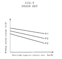
- Fig. 9 illustrates the relationship between the negative current rate Ren and the welding current average Iav, with the wire feeding speed kept constant. More specifically, the figure illustrates three cases where the wire feeding speed is set to F1, F2 and F3 (F1>F2>F3), and each graph shows, for the relevant one of the three speeds, how the welding current average Iav varies with the change of the negative current rate Ren. As seen from the figure, in the AC pulse arc welding, the welding current average Iav varies as the negative current rate Ren changes, even when the wire feeding speed is constant.
- the welding current average Iav is proportional to the heat input to the base material
- the wire feeding speed is proportional to the amount of deposition.
- the thickness of the plates determines an appropriate welding current average, and hence the wire feeding speed.
- a thin plate to be welded necessitates a small welding current average Iav, and a low wire feeding speed.
- the shortage of deposition is crucial.
- AC pulse arc welding By AC pulse arc welding, on the other hand, the setting of the wire feeding speed can be performed independently, to some extent, of the setting of the welding current average Iav. Thus, the above-described problem can be overcome by the AC pulse arc welding. In this sense, AC pulse arc welding is advantageous for the welding of thin base materials. AC pulse arc welding is often employed for the welding of aluminum parts, but is applicable to ferrous materials.
- the change in the negative current rate Ren leads to the change in the relationship between the wire feeding speed and the welding current average Iav, and this fact can be utilized for performing proper welding of thin plates.
- two important factors to be considered are penetration and gap allowance.
- a proper penetration is formed by proper heat input to the base material.
- the gap allowance the adjustable range of deposition should be sufficiently wide. In light of these, it is required that the welding current average Iav is adjusted to optimize the heat input to the base material, and that the negative current rate Ren is adjusted to optimize the wire feeding speed for attaining proper amount of deposition.
- Fig. 10 shows the relationship between the negative current rate Ren and the heat input to the base material, with the welding current average kept constant.
- the measurement of the heat input to the base material was conducted with the use of: a welding wire made of aluminum alloy A5356 and having a diameter of 1.2 mm; and a base material made of aluminum A052 and having a thickness of 4 mm.
- the AC pulse arc welding with respect to the base material was performed for 30 seconds, the welding speed was 60 cm/min, and the welding current average Iav was kept at 100 A.
- the wire feeding speed was adjusted so that the welding current average Iav remained constant, even when the negative current rate Ren changed.
- Fig. 11 illustrates the relationship between the negative current rate Ren and the gap allowance of the base materials, with the welding current average kept constant.
- the base materials were plates having a thickness of 1.0 mm and made of aluminum alloy A5052.
- the welding speed was 60 cm/min, and the welding current average Iav was kept at 60A.
- the maximum joint gap that allowed proper welding operation was determined.
- the gap allowance becomes greater as the negative current rate Ren becomes greater. This is because, as the negative current rate Ren increases, the wire feeding speed becomes faster, and therefore the amount of deposition becomes greater. Accordingly, even a wide gap can be filled with a greater amount of molten metal. In this manner, a wide gap in the metallic parts to be connected can be filled by increasing the negative current rate Ren.
- Proper heat input is determined by the thickness of base materials, the type of the joint, etc, and once the heat input is determined, a proper welding current average Iav is determined.
- a proper wire feeding speed is determined by the gap at the joint, and the wire feeding speed in turn determines a proper negative current rate Ren.
- proper welding current average Iav and negative current rate Ren are determined.
- the wire feeding speed and the negative current rate Ren are to be set for performing welding.
- the wire feeding speed setting signal Fs is adjusted for setting the welding current average Iav
- the negative current rate Ren will inevitably change.
- the negative current rate setting signal Rs is adjusted, not only the negative current rate Ren but also the welding current average Iav will change.
- the desired setting parameters i.e., the welding current average Iav and the negative current rate Ren
- the actual setting parameters i.e., the wire feeding speed and the negative current rate Ren
- the present invention has been proposed under the circumstances described above. It is therefore an object of the present invention to provide an AC pulse arc welding method whereby the setting of the welding current average and the setting of the electrode negative current rate can be conducted quickly and accurately with ease.
- an AC pulse arc welding method comprising: applying a periodic welding current that includes, for a pulse cycle, negative current in electrode negative polarity and positive current in electrode positive polarity; setting a negative current rate by a negative current rate setting value, the negative current rate representing a ratio of the negative current to the welding current for the pulse cycle; and setting a feeding speed of welding wire as a consumable electrode by a feeding speed setting value.
- the method comprises: setting an average of the welding current by a welding current setting value; and performing automatic calculation of the feeding speed setting value by using a predetermined conversion function based on input of the welding current setting value and the negative current rate setting value.
- the negative current rate may be a ratio of time integration of the negative current to time integration of the welding current for the one pulse cycle.
- the positive current for the one pulse cycle may comprise peak current and base current.
- the conversion function may comprise a group of functions corresponding to different negative current setting values, respectively.
- Each function belonging to the group may define a relationship between welding current setting values and feeding speed setting values for a relevant one of the negative current setting values.
- the AC pulse arc welding method of the present invention may further comprise the step of setting an average voltage applied between the welding wire and a base metal by a welding voltage setting value.
- the welding voltage setting value may be automatically calculated by a predetermined voltage setting function upon input of the welding current setting value.
- the welding current setting value Is determines the welding current average Iav
- the electrode negative current rate setting value Rs determines the electrode negative current rate Ren
- the wire feeding speed setting value Fsc is automatically calculated by a conversion function.
- the setting of the welding current average Iav can be conducted independently of the setting of the negative current rate Ren.
- the setting of the heat input to the base material (this setting is for attaining proper penetration in the base material) can be easily conducted based on the welding current setting value Is.
- the setting of the negative current rate Ren (this setting is for optimizing the amount of deposition in light of the gap between the base materials) can be easily conducted based on the negative current rate setting value Rs. Since the welding current average Iav and the negative current rate Ren can be set independently of each other, the human operator does not need much skill for using the welding system.
- Fig. 1 shows an AC pulse arc welder used for implementing a welding method according to the present invention.
- the elements identical or similar in function to those shown in Fig. 7 are designated by the same reference numerals or characters used in Fig. 7.
- the elements represented in solid lines may be the same for both the conventional welder (Fig. 7) and the welder of the present invention (Fig. 1), while the elements represented in broken lines in Fig. 1 have no counterparts in the conventional system shown in Fig. 7.
- the welding current setting circuit IS outputs a welding current setting signal Is for setting a welding current average.
- the wire feeding speed conversion circuit FSC receives the above-mentioned welding current setting signal Is and an electrode negative current rate setting signal Rs. Based on the input of these signals, the conversion circuit FSC calculates a wire feeding speed setting signal Fsc by a predetermined conversion function or functions (to be described later), and then outputs the signal Fsc to the power source 6.
- the outputted signal Fsc in itself is the same as the conventional feeding speed setting signal Fs.
- the power source 6 In addition to the signal Fsc, the power source 6 also receives a negative current rate setting signal Rs and a welding voltage setting signal Vs, as in the conventional welder.
- a conventionally available power source can be used as the power source 6 of the present invention.
- the welding current setting circuit IS, the current rate setting circuit RS, the welding voltage setting circuit VS and the conversion circuit FSC may be incorporated in the power source 6 as one unit.
- the setting of the welding current average and the setting of the negative current rate can be conducted independently of each other.
- the desired condition settings can be performed quickly and accurately with ease.
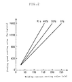
- Fig. 2 is a graph showing some examples of conversion functions mentioned above. Each conversion function describes the relationship between the welding current setting signal (or value) Is and the wire feeding speed setting signal (or value) Fsc for a constant negative current rate Rs (0%, 20%, 40%).
- Fsc F(Is, Rs).
- Fig. 3 An example of the function f1 in formula (2) is illustrated in Fig. 3, which describes the relationship between the negative current rate setting signal Rs and the first parameter "a.”
- Fig. 4 An example of the function f2 in formula (3) is illustrated in Fig. 4, which describes the relationship between the negative current rate setting signal Rs and the second parameter "b.”
- a plurality of functions each corresponding to the relevant one of the current rate setting signals Rs, are predetermined.
- the constants ai, bj (i,j - 0-40) may be experimentally worked out.
- the range of the setting signal Rs may be 0 to 40%, as in the above example, though the present invention is not limited to this.
- the increment of Rs is one, though the present invention is not limited to this.
- Fig. 5 illustrates a second example of an AC pulse arc welder used for implementing a welding method of the present invention.
- the elements represented in solid lines in Fig. 5 are the same as those shown in Fig. 1 denoted by the same reference numerals or characters.
- the second welder shown in Fig. 5 is different from the first welder shown in Fig. 1 in comprising a one-variable, voltage function circuit VSC, represented in broken lines.
- the voltage function circuit VSC calculates a welding voltage setting signal Vsc by using a predetermined voltage function (to be described below).
- a conventionally available power source can be used as the power source 6, since the voltage setting signal Vsc in itself is the same as the voltage setting signal Vs shown in Fig. 1.
- the welding current setting circuit IS, the electrode negative current rate setting circuit RS, the wire feeding speed conversion circuit FSC, and the voltage function circuit VSC may be incorporated in the power source 6 as one unit.
- an appropriate welding voltage average Vav welding voltage setting signal Vsc
- Iav welding current setting signal Is
- Fig. 6 is a graph illustrating an example of the relationship between the welding current setting signal Is and the welding voltage setting signal Vsc.
- the graph illustrates an example of a voltage function.
- use is made of a welding wire having a diameter of 1.2 mm and made of aluminum A5356.
- the voltage function in this example is represented by a straight line.
Landscapes
- Engineering & Computer Science (AREA)
- Physics & Mathematics (AREA)
- Plasma & Fusion (AREA)
- Mechanical Engineering (AREA)
- Theoretical Computer Science (AREA)
- Arc Welding Control (AREA)
- Arc Welding In General (AREA)
Applications Claiming Priority (2)
| Application Number | Priority Date | Filing Date | Title |
|---|---|---|---|
| JP2004184532A JP4319586B2 (ja) | 2004-06-23 | 2004-06-23 | 交流パルスアーク溶接方法 |
| JP2004184532 | 2004-06-23 |
Publications (3)
| Publication Number | Publication Date |
|---|---|
| EP1609554A2 true EP1609554A2 (fr) | 2005-12-28 |
| EP1609554A3 EP1609554A3 (fr) | 2007-10-31 |
| EP1609554B1 EP1609554B1 (fr) | 2008-10-22 |
Family
ID=34941741
Family Applications (1)
| Application Number | Title | Priority Date | Filing Date |
|---|---|---|---|
| EP05253848A Expired - Lifetime EP1609554B1 (fr) | 2004-06-23 | 2005-06-21 | Procédé de soudage avec courant alternatif pulse |
Country Status (6)
| Country | Link |
|---|---|
| US (1) | US7235760B2 (fr) |
| EP (1) | EP1609554B1 (fr) |
| JP (1) | JP4319586B2 (fr) |
| CN (1) | CN100460121C (fr) |
| AT (1) | ATE411865T1 (fr) |
| DE (1) | DE602005010509D1 (fr) |
Cited By (2)
| Publication number | Priority date | Publication date | Assignee | Title |
|---|---|---|---|---|
| WO2009129551A1 (fr) * | 2008-04-21 | 2009-10-29 | Fronius International Gmbh | Procédé de réglage d’un appareil de soudage |
| RU2597855C1 (ru) * | 2015-03-23 | 2016-09-20 | Федеральное государственное автономное образовательное учреждение высшего образования "Национальный исследовательский Томский политехнический университет" | Способ управления процессом механизированной сварки в среде защитных газов с подачей сварочной проволоки |
Families Citing this family (18)
| Publication number | Priority date | Publication date | Assignee | Title |
|---|---|---|---|---|
| US8895896B2 (en) * | 2004-01-12 | 2014-11-25 | Lincoln Global, Inc. | Modified series arc welding and improved control of one sided series arc welding |
| JP2008018436A (ja) * | 2006-07-11 | 2008-01-31 | Yorozu Corp | 溶接方法および溶接物 |
| PL1958724T3 (pl) * | 2007-02-13 | 2011-10-31 | Pangas | Sposób spajania łukiem elektrycznym z zastosowaniem prądu przemiennego |
| JP4995697B2 (ja) * | 2007-11-12 | 2012-08-08 | 株式会社ダイヘン | ステッチパルス溶接装置 |
| JP5120073B2 (ja) * | 2008-05-30 | 2013-01-16 | 株式会社安川電機 | 交流パルスアーク溶接装置および制御方法 |
| JP5557238B2 (ja) * | 2008-12-24 | 2014-07-23 | 株式会社ダイヘン | 交流パルスアーク溶接制御方法 |
| JP5263288B2 (ja) * | 2009-01-28 | 2013-08-14 | パナソニック株式会社 | 交流パルスアーク溶接方法 |
| JP4807474B2 (ja) * | 2009-06-19 | 2011-11-02 | パナソニック株式会社 | 消耗電極式アーク溶接方法および消耗電極式アーク溶接装置 |
| JP5622230B2 (ja) * | 2010-09-29 | 2014-11-12 | 株式会社ダイヘン | 交流パルスアーク溶接制御方法 |
| CN102873433B (zh) * | 2012-07-03 | 2014-11-26 | 广东技术师范学院 | 一种双丝弧焊送丝速度预测设定方法 |
| US9676051B2 (en) | 2012-10-18 | 2017-06-13 | Lincoln Global, Inc. | System and methods providing modulation schemes for achieving a weld bead appearance |
| JP2014184452A (ja) * | 2013-03-22 | 2014-10-02 | Daihen Corp | アーク溶接用電源装置及びアーク溶接用電源装置の制御方法 |
| US10052707B2 (en) * | 2014-04-04 | 2018-08-21 | Lincoln Global, Inc. | Method and system to use AC welding waveform and enhanced consumable to improve welding of galvanized workpiece |
| KR102306504B1 (ko) * | 2014-08-18 | 2021-09-28 | 가부시키가이샤 다이헨 | 아크 용접 제어 방법 |
| JP6814948B2 (ja) * | 2016-02-04 | 2021-01-20 | パナソニックIpマネジメント株式会社 | パルスアーク溶接制御方法およびパルスアーク溶接装置 |
| KR102266341B1 (ko) * | 2016-10-24 | 2021-06-16 | 가부시키가이샤 다이헨 | 교류 펄스 아크 용접 제어 방법 |
| US12115604B2 (en) * | 2018-10-19 | 2024-10-15 | Illinois Tool Works Inc. | Systems and methods for voltage control of a short circuit during a pulse welding process |
| CN117483919A (zh) * | 2023-11-27 | 2024-02-02 | 国家石油天然气管网集团有限公司 | Tig自动焊送丝控制方法、系统、装置、计算设备及介质 |
Family Cites Families (6)
| Publication number | Priority date | Publication date | Assignee | Title |
|---|---|---|---|---|
| JP2892198B2 (ja) | 1991-09-30 | 1999-05-17 | 株式会社神戸製鋼所 | 消耗電極式交流パルスアーク溶接方法 |
| JPH10277740A (ja) * | 1997-04-01 | 1998-10-20 | Kobe Steel Ltd | パルスアーク溶接装置 |
| JPH10286671A (ja) * | 1997-04-11 | 1998-10-27 | Kobe Steel Ltd | 消耗電極式交流パルスアーク溶接装置 |
| JP2000326026A (ja) * | 1999-05-21 | 2000-11-28 | Miyachi Technos Corp | ヒュージング加工方法 |
| JP3641174B2 (ja) * | 1999-11-24 | 2005-04-20 | 株式会社ダイヘン | 交流パルスアーク溶接の制御方法及び溶接電源装置 |
| JP4846898B2 (ja) * | 2000-09-12 | 2011-12-28 | 株式会社ダイヘン | 交流パルスアーク溶接制御方法及び溶接電源装置 |
-
2004
- 2004-06-23 JP JP2004184532A patent/JP4319586B2/ja not_active Expired - Fee Related
-
2005
- 2005-06-17 US US11/155,645 patent/US7235760B2/en not_active Expired - Lifetime
- 2005-06-21 CN CNB2005100789865A patent/CN100460121C/zh not_active Expired - Fee Related
- 2005-06-21 DE DE602005010509T patent/DE602005010509D1/de not_active Expired - Lifetime
- 2005-06-21 AT AT05253848T patent/ATE411865T1/de not_active IP Right Cessation
- 2005-06-21 EP EP05253848A patent/EP1609554B1/fr not_active Expired - Lifetime
Cited By (4)
| Publication number | Priority date | Publication date | Assignee | Title |
|---|---|---|---|---|
| WO2009129551A1 (fr) * | 2008-04-21 | 2009-10-29 | Fronius International Gmbh | Procédé de réglage d’un appareil de soudage |
| RU2484931C2 (ru) * | 2008-04-21 | 2013-06-20 | Фрониус Интернэшнл Гмбх | Способ управления сварочным аппаратом |
| US9492879B2 (en) | 2008-04-21 | 2016-11-15 | Fronius International Gmbh | Method for controlling a welder |
| RU2597855C1 (ru) * | 2015-03-23 | 2016-09-20 | Федеральное государственное автономное образовательное учреждение высшего образования "Национальный исследовательский Томский политехнический университет" | Способ управления процессом механизированной сварки в среде защитных газов с подачей сварочной проволоки |
Also Published As
| Publication number | Publication date |
|---|---|
| JP2006007239A (ja) | 2006-01-12 |
| US7235760B2 (en) | 2007-06-26 |
| CN1712169A (zh) | 2005-12-28 |
| DE602005010509D1 (de) | 2008-12-04 |
| EP1609554A3 (fr) | 2007-10-31 |
| ATE411865T1 (de) | 2008-11-15 |
| CN100460121C (zh) | 2009-02-11 |
| JP4319586B2 (ja) | 2009-08-26 |
| EP1609554B1 (fr) | 2008-10-22 |
| US20050284854A1 (en) | 2005-12-29 |
Similar Documents
| Publication | Publication Date | Title |
|---|---|---|
| EP1609554B1 (fr) | Procédé de soudage avec courant alternatif pulse | |
| Kah et al. | Advanced gas metal arc welding processes | |
| EP3062950B1 (fr) | Extraction de longueur d'arc d'une tension et rétroaction de courant | |
| EP1864746B1 (fr) | Appareil pour soudure à arc en série amélioré avec dispositifs de contrôle de la vitesse de fil | |
| EP2576118B1 (fr) | Système de soudage à l'arc court | |
| JP3206714B2 (ja) | パルスアーク溶接方法および装置 | |
| US8937267B2 (en) | Method and system to increase heat input to a weld during a short-circuit arc welding process | |
| US9511442B2 (en) | Adaptable rotating arc welding method and system | |
| US20140124492A1 (en) | Method and system to control heat input in a welding operation | |
| EP0868959A1 (fr) | Dispositif de soudage à l'arc pulsé | |
| JPH11226730A (ja) | 消耗電極式の交流ガスシールド溶接方法および装置 | |
| Dinbandhu et al. | Advances in gas metal arc welding process: modifications in short-circuiting transfer mode | |
| JPH11267839A (ja) | アーク溶接方法 | |
| WO2008091280A2 (fr) | Commande à boucle externe destinée à être utilisée avec des alliages d'apport de nickel et acier inoxydable duplex et gaz protecteur contenant du dioxyde de carbone | |
| EP2576119B1 (fr) | Système de soudage à l'arc court | |
| US12465992B2 (en) | Systems and methods for controlled arc and short phase time adjustment | |
| JP2022157591A (ja) | 溶接制御方法、溶接電源、溶接システム、溶接方法及び積層造形方法 | |
| EP1779957B1 (fr) | Système de soudage synergique | |
| Kah et al. | Modified GMAW processes: Control of heat input | |
| CN111843112B (zh) | 用于控制焊接功率和预加热功率的方法和设备 | |
| JPH06190561A (ja) | パルスmagアーク溶接方法及び溶接装置 | |
| JP4673519B2 (ja) | 交流ガスシールドアーク溶接の送給制御方法 | |
| JPH05138355A (ja) | 消耗電極式ガスシールドアーク溶接方法および装置 | |
| JP2008080355A (ja) | プラズマミグ溶接方法 | |
| JP2005144468A (ja) | 交流アーク溶接のガス流量調整方法 |
Legal Events
| Date | Code | Title | Description |
|---|---|---|---|
| PUAI | Public reference made under article 153(3) epc to a published international application that has entered the european phase |
Free format text: ORIGINAL CODE: 0009012 |
|
| AK | Designated contracting states |
Kind code of ref document: A2 Designated state(s): AT BE BG CH CY CZ DE DK EE ES FI FR GB GR HU IE IS IT LI LT LU MC NL PL PT RO SE SI SK TR |
|
| AX | Request for extension of the european patent |
Extension state: AL BA HR LV MK YU |
|
| PUAL | Search report despatched |
Free format text: ORIGINAL CODE: 0009013 |
|
| AK | Designated contracting states |
Kind code of ref document: A3 Designated state(s): AT BE BG CH CY CZ DE DK EE ES FI FR GB GR HU IE IS IT LI LT LU MC NL PL PT RO SE SI SK TR |
|
| AX | Request for extension of the european patent |
Extension state: AL BA HR LV MK YU |
|
| 17P | Request for examination filed |
Effective date: 20080110 |
|
| GRAP | Despatch of communication of intention to grant a patent |
Free format text: ORIGINAL CODE: EPIDOSNIGR1 |
|
| AKX | Designation fees paid |
Designated state(s): AT DE FR GB IT |
|
| GRAS | Grant fee paid |
Free format text: ORIGINAL CODE: EPIDOSNIGR3 |
|
| GRAA | (expected) grant |
Free format text: ORIGINAL CODE: 0009210 |
|
| AK | Designated contracting states |
Kind code of ref document: B1 Designated state(s): AT DE FR GB IT |
|
| REG | Reference to a national code |
Ref country code: GB Ref legal event code: FG4D |
|
| REF | Corresponds to: |
Ref document number: 602005010509 Country of ref document: DE Date of ref document: 20081204 Kind code of ref document: P |
|
| PG25 | Lapsed in a contracting state [announced via postgrant information from national office to epo] |
Ref country code: AT Free format text: LAPSE BECAUSE OF FAILURE TO SUBMIT A TRANSLATION OF THE DESCRIPTION OR TO PAY THE FEE WITHIN THE PRESCRIBED TIME-LIMIT Effective date: 20081022 |
|
| PLBE | No opposition filed within time limit |
Free format text: ORIGINAL CODE: 0009261 |
|
| STAA | Information on the status of an ep patent application or granted ep patent |
Free format text: STATUS: NO OPPOSITION FILED WITHIN TIME LIMIT |
|
| 26N | No opposition filed |
Effective date: 20090723 |
|
| GBPC | Gb: european patent ceased through non-payment of renewal fee |
Effective date: 20090621 |
|
| PG25 | Lapsed in a contracting state [announced via postgrant information from national office to epo] |
Ref country code: GB Free format text: LAPSE BECAUSE OF NON-PAYMENT OF DUE FEES Effective date: 20090621 |
|
| REG | Reference to a national code |
Ref country code: FR Ref legal event code: PLFP Year of fee payment: 12 |
|
| REG | Reference to a national code |
Ref country code: FR Ref legal event code: PLFP Year of fee payment: 13 |
|
| REG | Reference to a national code |
Ref country code: FR Ref legal event code: PLFP Year of fee payment: 14 |
|
| PGFP | Annual fee paid to national office [announced via postgrant information from national office to epo] |
Ref country code: FR Payment date: 20210513 Year of fee payment: 17 Ref country code: DE Payment date: 20210525 Year of fee payment: 17 Ref country code: IT Payment date: 20210511 Year of fee payment: 17 |
|
| REG | Reference to a national code |
Ref country code: DE Ref legal event code: R119 Ref document number: 602005010509 Country of ref document: DE |
|
| PG25 | Lapsed in a contracting state [announced via postgrant information from national office to epo] |
Ref country code: FR Free format text: LAPSE BECAUSE OF NON-PAYMENT OF DUE FEES Effective date: 20220630 |
|
| PG25 | Lapsed in a contracting state [announced via postgrant information from national office to epo] |
Ref country code: DE Free format text: LAPSE BECAUSE OF NON-PAYMENT OF DUE FEES Effective date: 20230103 |
|
| PG25 | Lapsed in a contracting state [announced via postgrant information from national office to epo] |
Ref country code: IT Free format text: LAPSE BECAUSE OF NON-PAYMENT OF DUE FEES Effective date: 20220621 |