EP1637388A2 - Système de contrôle de stabilité de véhicule - Google Patents
Système de contrôle de stabilité de véhicule Download PDFInfo
- Publication number
- EP1637388A2 EP1637388A2 EP05017427A EP05017427A EP1637388A2 EP 1637388 A2 EP1637388 A2 EP 1637388A2 EP 05017427 A EP05017427 A EP 05017427A EP 05017427 A EP05017427 A EP 05017427A EP 1637388 A2 EP1637388 A2 EP 1637388A2
- Authority
- EP
- European Patent Office
- Prior art keywords
- vibration
- physical quantity
- vehicle
- engine
- control system
- Prior art date
- Legal status (The legal status is an assumption and is not a legal conclusion. Google has not performed a legal analysis and makes no representation as to the accuracy of the status listed.)
- Withdrawn
Links
Images




Classifications
-
- B—PERFORMING OPERATIONS; TRANSPORTING
- B60—VEHICLES IN GENERAL
- B60W—CONJOINT CONTROL OF VEHICLE SUB-UNITS OF DIFFERENT TYPE OR DIFFERENT FUNCTION; CONTROL SYSTEMS SPECIALLY ADAPTED FOR HYBRID VEHICLES; ROAD VEHICLE DRIVE CONTROL SYSTEMS FOR PURPOSES NOT RELATED TO THE CONTROL OF A PARTICULAR SUB-UNIT
- B60W10/00—Conjoint control of vehicle sub-units of different type or different function
- B60W10/04—Conjoint control of vehicle sub-units of different type or different function including control of propulsion units
- B60W10/08—Conjoint control of vehicle sub-units of different type or different function including control of propulsion units including control of electric propulsion units, e.g. motors or generators
-
- B—PERFORMING OPERATIONS; TRANSPORTING
- B60—VEHICLES IN GENERAL
- B60G—VEHICLE SUSPENSION ARRANGEMENTS
- B60G2400/00—Indexing codes relating to detected, measured or calculated conditions or factors
- B60G2400/05—Attitude
- B60G2400/051—Angle
- B60G2400/0512—Pitch angle
-
- B—PERFORMING OPERATIONS; TRANSPORTING
- B60—VEHICLES IN GENERAL
- B60G—VEHICLE SUSPENSION ARRANGEMENTS
- B60G2400/00—Indexing codes relating to detected, measured or calculated conditions or factors
- B60G2400/05—Attitude
- B60G2400/053—Angular acceleration
- B60G2400/0532—Pitch acceleration
-
- B—PERFORMING OPERATIONS; TRANSPORTING
- B60—VEHICLES IN GENERAL
- B60G—VEHICLE SUSPENSION ARRANGEMENTS
- B60G2800/00—Indexing codes relating to the type of movement or to the condition of the vehicle and to the end result to be achieved by the control action
- B60G2800/01—Attitude or posture control
- B60G2800/014—Pitch; Nose dive
-
- B—PERFORMING OPERATIONS; TRANSPORTING
- B60—VEHICLES IN GENERAL
- B60W—CONJOINT CONTROL OF VEHICLE SUB-UNITS OF DIFFERENT TYPE OR DIFFERENT FUNCTION; CONTROL SYSTEMS SPECIALLY ADAPTED FOR HYBRID VEHICLES; ROAD VEHICLE DRIVE CONTROL SYSTEMS FOR PURPOSES NOT RELATED TO THE CONTROL OF A PARTICULAR SUB-UNIT
- B60W30/00—Purposes of road vehicle drive control systems not related to the control of a particular sub-unit, e.g. of systems using conjoint control of vehicle sub-units
- B60W30/02—Control of vehicle driving stability
- B60W30/04—Control of vehicle driving stability related to roll-over prevention
- B60W2030/041—Control of vehicle driving stability related to roll-over prevention about the pitch axis
-
- B—PERFORMING OPERATIONS; TRANSPORTING
- B60—VEHICLES IN GENERAL
- B60W—CONJOINT CONTROL OF VEHICLE SUB-UNITS OF DIFFERENT TYPE OR DIFFERENT FUNCTION; CONTROL SYSTEMS SPECIALLY ADAPTED FOR HYBRID VEHICLES; ROAD VEHICLE DRIVE CONTROL SYSTEMS FOR PURPOSES NOT RELATED TO THE CONTROL OF A PARTICULAR SUB-UNIT
- B60W40/00—Estimation or calculation of non-directly measurable driving parameters for road vehicle drive control systems not related to the control of a particular sub unit, e.g. by using mathematical models
- B60W40/12—Estimation or calculation of non-directly measurable driving parameters for road vehicle drive control systems not related to the control of a particular sub unit, e.g. by using mathematical models related to parameters of the vehicle itself, e.g. tyre models
- B60W40/13—Load or weight
- B60W2040/1323—Moment of inertia of the vehicle body
- B60W2040/1338—Moment of inertia of the vehicle body about the pitch axis
-
- B—PERFORMING OPERATIONS; TRANSPORTING
- B60—VEHICLES IN GENERAL
- B60W—CONJOINT CONTROL OF VEHICLE SUB-UNITS OF DIFFERENT TYPE OR DIFFERENT FUNCTION; CONTROL SYSTEMS SPECIALLY ADAPTED FOR HYBRID VEHICLES; ROAD VEHICLE DRIVE CONTROL SYSTEMS FOR PURPOSES NOT RELATED TO THE CONTROL OF A PARTICULAR SUB-UNIT
- B60W40/00—Estimation or calculation of non-directly measurable driving parameters for road vehicle drive control systems not related to the control of a particular sub unit, e.g. by using mathematical models
- B60W40/10—Estimation or calculation of non-directly measurable driving parameters for road vehicle drive control systems not related to the control of a particular sub unit, e.g. by using mathematical models related to vehicle motion
- B60W40/11—Pitch movement
-
- B—PERFORMING OPERATIONS; TRANSPORTING
- B60—VEHICLES IN GENERAL
- B60W—CONJOINT CONTROL OF VEHICLE SUB-UNITS OF DIFFERENT TYPE OR DIFFERENT FUNCTION; CONTROL SYSTEMS SPECIALLY ADAPTED FOR HYBRID VEHICLES; ROAD VEHICLE DRIVE CONTROL SYSTEMS FOR PURPOSES NOT RELATED TO THE CONTROL OF A PARTICULAR SUB-UNIT
- B60W40/00—Estimation or calculation of non-directly measurable driving parameters for road vehicle drive control systems not related to the control of a particular sub unit, e.g. by using mathematical models
- B60W40/10—Estimation or calculation of non-directly measurable driving parameters for road vehicle drive control systems not related to the control of a particular sub unit, e.g. by using mathematical models related to vehicle motion
- B60W40/112—Roll movement
-
- B—PERFORMING OPERATIONS; TRANSPORTING
- B60—VEHICLES IN GENERAL
- B60W—CONJOINT CONTROL OF VEHICLE SUB-UNITS OF DIFFERENT TYPE OR DIFFERENT FUNCTION; CONTROL SYSTEMS SPECIALLY ADAPTED FOR HYBRID VEHICLES; ROAD VEHICLE DRIVE CONTROL SYSTEMS FOR PURPOSES NOT RELATED TO THE CONTROL OF A PARTICULAR SUB-UNIT
- B60W40/00—Estimation or calculation of non-directly measurable driving parameters for road vehicle drive control systems not related to the control of a particular sub unit, e.g. by using mathematical models
- B60W40/10—Estimation or calculation of non-directly measurable driving parameters for road vehicle drive control systems not related to the control of a particular sub unit, e.g. by using mathematical models related to vehicle motion
- B60W40/114—Yaw movement
Definitions
- the present invention relates to a vehicle stability control system for suppressing vibrations generated during running of a vehicle.
- a regenerative brake which is designed to produce braking force using a braking apparatus as well as an engine load apparatus, such as an alternator, during braking of the vehicle.
- An example of such a system is disclosed in Japanese Patent Laid-Open Publication No. Hei 10-285706.
- the regenerative brake actively turns on an engine load, such as an alternator, during braking of the vehicle in order to absorb kinetic energy of the vehicle, thereby supplementing the braking capability of the braking apparatus.
- One of the factors includes the fact that more kinetic energy may be produced than is required for the vehicle to run.
- an insufficient amount of kinetic energy may be produced. For example, assuming that the vehicle body is maintained horizontally when in a stable state, a squat may occur which causes the front of the vehicle to displace upward from the stable state due to an excessive drive torque. Additionally, a nosedive may occur which causes the front of the vehicle to displace downward from the stable state due to a drive torque reactive force generated during braking. The squat and the nosedive result from kinetic energy that is produced beyond that which is required for the vehicle to run.
- the aforementioned conventional regenerative brake is designed to impose a load on the engine to supplement the braking capability of the braking apparatus.
- the present invention was developed in view of the aforementioned and other problems.
- the principles of the present invention provide a vehicle stability control system and a method for offsetting vibrations generated during running of the vehicle.
- the system and the method are adapted to remove vibrations by establishing an engine load to absorb kinetic energy provided beyond that which is required or to supplement the engine power when the required kinetic energy cannot be obtained.
- Fig. 8 shows various kinetic energies provided by a vehicle.
- the kinetic energies of the vehicle include the pitching rotational energy, the rolling rotational energy, and the yawing rotational energy.
- the translational energy in the X-direction (along which the vehicle travels), the translational energy in the Y-direction (or the lateral direction of the vehicle), and the translational energy in the Z-direction (or the vertical direction of the vehicle).
- the pitching vibrational energy refers to the rotational vibrational energy in the pitching direction.
- the pitching direction is defined as rotating about the vehicle axis in the lateral direction with the center of gravity of the vehicle as its center.
- the pitching vibrational energy results from a squat caused during acceleration, as shown in Fig. 9A. Additionally, a nosedive caused during deceleration may occur, as shown in Fig. 9B, or during turning, as shown in Fig. 9C.
- one aspect of the present invention provides a vehicle stability control system which uses a physical quantity corresponding to a driver accelerator input to control engine power produced by an engine, as well as to controllably drive an engine load for regulating the engine power, thereby producing a desired drive force.
- the vehicle stability control system includes vibration detection means for determining a vibration during running of the vehicle.
- the system also includes correction means for driving the engine load to suppress the vibration in response to the vibration determined by the vibration detection means.
- the system drives the engine load in response to the vibration that disturbs the stability of the vehicle.
- the engine load suppresses the vibration. This makes it possible to prevent the stability of the vehicle from being disturbed due to the vibration.
- the vibration detection means can determine a vehicle body input torque and estimate the vibration based on the vehicle body input torque. More specifically, in another aspect of the present invention, the vibration detection means can detect the vibration corresponding to the vehicle body input torque in accordance with an on-spring vehicle body vibration model developed in view of the vibration of the on-spring vehicle body itself that is supported by the front and rear wheel suspensions of the vehicle.
- the correction means can subtract the physical quantity corresponding to the vibration from a physical quantity corresponding to a drive force generated by the motor to take the resulting physical quantity as a physical quantity corresponding to the proportion of the post-correction drive force for the motor generator.
- the correction means can subtract the physical quantity corresponding to the vibration from a physical quantity corresponding to a drive force reduced by the generator to take the resulting physical quantity as a physical quantity corresponding to the proportion of the post-correction drive force for the motor generator.
- a still further aspect of the present invention supposes that the engine load is a starter or an alternator.
- the correction means when the corrected vibration-based physical quantity is negative, the correction means outputs the vibration-based physical quantity as an instruction signal for driving the alternator.
- the vibration-based physical quantity When the vibration-based physical quantity is positive, the correction means outputs the vibration-based physical quantity as an instruction signal for driving the starter.
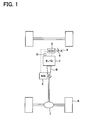
- FIG. 1 schematically shows the configuration of the vehicle stability control system according to this embodiment.
- a rear-wheel drive vehicle is used for explanatory purposes; however, the present invention is also applicable to a front-wheel drive vehicle or a four-wheel drive vehicle.
- the vehicle stability control system is configured to suppress a vibration, which may disturb the stability of the vehicle, by regulating the drive torque generated by an engine 1 included in the vehicle using a motor generator 2 serving as an engine load device to establish an engine load.
- a vibration which may disturb the stability of the vehicle
- a motor generator 2 serving as an engine load device to establish an engine load.
- the description is given to an example in which the pitching vibration is suppressed.
- Fig. 2 schematically shows the configuration of the engine ECU 3 in a block diagram.
- the engine ECU 3 includes a required drive force computational portion 3a, a pitching vibration suppression corrective portion 3b, and an actuator instruction computational portion 3c.
- a detected signal corresponding to the amount of operation of an accelerator pedal 4 is delivered from a pedal stroke sensor 5 as a physical quantity corresponding to the driver accelerator input.
- the required drive force computational portion 3a determines the amount of operation of the accelerator pedal 4 based on the detected signal, and determines the required axle shaft torque serving as a required drive force corresponding to the amount of operation.
- the drive torque required by the driver, as determined here, is to be the torque used in accelerating and decelerating the vehicle and is referred to as the required axle shaft torque.
- the required drive force computational portion 3a delivers an instructional signal to the engine 1 and the motor generator 2 in order to allow the engine 1 and the motor generator 2 to produce the axle shaft torque in accordance with their respective proportions.
- the proportion of the axle shaft torque to be generated by the motor generator 2 also serves to determine how the motor generator 2 should be actuated.
- the motor generator 2 serves as a motor as well as a generator.
- the motor generator 2 serves as a motor in a region where the engine has bad efficiency, such as when the vehicle is accelerated from rest.
- the motor generator 2 stops in a region where the engine has good efficiency, such as when the vehicle is running at an intermittent or low speed load.
- the motor generator 2 serves as a generator when the accelerator is released such as during deceleration and braking.
- the pitching vibration suppression corrective portion 3b corrects the drive torque allocated to the motor generator 2.
- the pitching vibration suppression corrective portion 3b corresponds to the vibration detection means and the correction means referred to herein.
- the pitching vibration suppression corrective portion 3b performs such a correction. More specifically, the pitching vibration suppression corrective portion 3b determines a vehicle body input torque based on a detected signal, such as from a sensor 9 for sensing the amount of intake air or a current sensor of the motor generator 2. The pitching vibration suppression corrective portion 3b then determines the possible pitching vibration in accordance with the vehicle body input torque and delivers an instruction signal for driving the motor generator 2 in order to suppress the pitching vibration.
- a detected signal such as from a sensor 9 for sensing the amount of intake air or a current sensor of the motor generator 2.
- the pitching vibration suppression corrective portion 3b determines the possible pitching vibration in accordance with the vehicle body input torque and delivers an instruction signal for driving the motor generator 2 in order to suppress the pitching vibration.
- Fig. 3 shows a schematic diagram of the pitching vibration suppression corrective portion 3b.
- the pitching vibration suppression corrective portion 3b uses an on-spring vibration model to determine the pitching vibrational energy from the vehicle body input torque that is determined, such as from the detected signal provided by an intake-air quantity sensor 9. The pitching vibration suppression corrective portion 3b then determines the torque required to remove the pitching vibrational energy.
- the on-spring vibration model is defined as will be explained below. Now, the on-spring vibration model is explained with reference to a schematic view of the on-spring vibration model shown in Fig. 4.
- This on-spring vibration model relies on whether the on-spring portion would be subjected to a total torque reaction Tr at a driving wheel speed of ⁇ w to be vibrated about the pitching center.
- the on-spring vibration is modeled on the assumption that the vehicle body is considered to be a flat plate on an arbitrary horizontally-parallel reference plane, with the tires being suspended by a suspension and the engine 1 or the like being mounted on the flat plate.
- the radius r of the tires are also defined.
- the vehicle body mass M(kg) on the spring is also defined, the mass m(kg) of the engine 1 and the T/M 6 combined, the wheel base L(m), and the distance Lfo(m) between the center of gravity of the vehicle and the front axle shaft.
- the distance Lro(m) between the center of gravity of the vehicle and the rear axle shaft is also defined.
- the distance hc(m) between the the height of the reference plane serving as the vehicle body reference line and the height of the center of gravity of the vehicle.
- the virtual pitch angle about the pitching center is expressed by ⁇ P . Accordingly, the amount of displacement about the pitch center of the front axle shaft spaced apart by Lfo from the pitching center is expressed by Lf ⁇ P , and the amount of displacement about the pitch center of the rear axle shaft spaced apart by Lro from the pitching center is expressed by Lr ⁇ P .
- A [ 0 1 0 0 0 0 a 1 a 2 a 3 a 4 a 5 a 6 0 0 0 1 0 0 b 1 b 2 b 3 b 4 b 5 b 6 0 0 0 0 0 0 1 c 1 c 2 c 3 c 4 c 5 c 6 ]
- B [ 0 0 0 0 0 0 p 1 ] T
- This equation of state is used to calculate the amount of correction for suppressing the pitching vibration.
- a known technique such as a technique for designing an optimized regulator, may be used to determine the state feedback gain K.
- the technique will not be detailed herein.
- K is a designed value, which is defined in accordance with the aforementioned independent variables or constants, while KDiff is a value to be determined by the gear ratio of the final reduction gear 7.
- the actuator instruction computational portion 3c delivers to the motor generator 2 an instruction signal corresponding with the post-correction required axle shaft torque.
- the motor generator 2 will serve as either a motor or a generator, or stop, thereby generating the post-correction required axle shaft torque.
- Figs. 5 and 6 show actual running data on a vehicle, running on a highway and equipped with the vehicle stability control system of this embodiment.
- Fig. 5 shows the vehicle speed and the accelerator opening in the form of a timing chart.
- Fig. 6 shows, in the form of a timing chart, the correction torque provided by the motor generator 2 with the same timing as in Fig. 5.
- the correction axle shaft torque provided by the motor generator 2 varies, as shown in Fig. 6.
- the axle shaft torque for absorbing the excessive energy is the correction axle shaft torque.
- the axle shaft torque for supplementing the lack of energy is the correction axle shaft torque.
- the motor generator 2 can be used as a motor or a generator to regulate the engine energy, thereby removing the pitching vibration. This makes it possible to prevent the stability of the vehicle from being disturbed due to the pitching vibration, thus realizing stabilized running of the vehicle.
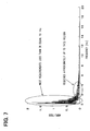
- Fig. 7 provides a graph illustrating a frequency study of the variations in correction axle shaft torque provided by the motor generator 2.
- the frequency strength distribution is highly intensive in a region of frequencies less than or equal to 1 Hz, with most frequencies concentrated in a region less than or equal to 4Hz. For this reason, the region that is necessary for frequency response of the motor generator 2 is conceivably at approximately 4Hz or less.
- a performance at 5 to 10 times the required frequency is sufficient as the frequency response of the motor generator 2.
- the motor generator 2 can sufficiently regulate the correction axle shaft torque in this embodiment.
- the vehicle stability control system of this embodiment can suppress the pitching vibration. This makes it possible to prevent the stability of the vehicle from being disturbed due to the pitching vibration, thus realizing stabilized running of the vehicle.
- the vibrational energy is removed in this manner, thereby making it possible to adjust the engine energy to a better value of efficiency, as well as to improve fuel efficiency. Still further, the excessive energy can be used for generating electric power, thereby allowing the electric energy to be utilized efficiently.
- the aforementioned embodiment uses the motor generator 2 as the engine load device, in which the motor generator 2 is used as a motor and a generator, thereby addressing both the cases where the corrected physical quantity corresponding to the pitching vibration is positive and negative.
- the motor generator 2 is only one example of the engine load device; other load devices, such as one including a starter and an alternator may also be employed. In this case, the combination of the starter and the alternator could also address both the cases where the corrected physical quantity corresponding to the pitching vibration is positive and negative.
- the aforementioned embodiment allows the engine ECU 3 to determine the instruction signal for the motor generator 2; however, other aspects of the system other than the engine ECU 3 may also employed.
- the required drive force is calculated generally in the engine ECU 3, it is also possible to obtain the torque used for acceleration and deceleration of the vehicle from a calculation result provided by the engine ECU 3.
- the aforementioned embodiment directly determines a physical quantity, which is the axle shaft torque corresponding to the drive force, in order to remove the pitching vibrational energy.
- a physical quantity which is the axle shaft torque corresponding to the drive force
- other physical quantities may also be employed, or a converted physical quantity corresponding to the axle shaft torque may be employed to carry out each of the aforementioned calculations.
- Such a vibration may include a rolling vibration of the vehicle, a vertical vibration of the vehicle, a vertical vibration of the engine, and a slant angle vibration of the engine.
Landscapes
- Engineering & Computer Science (AREA)
- Chemical & Material Sciences (AREA)
- Combustion & Propulsion (AREA)
- Transportation (AREA)
- Mechanical Engineering (AREA)
- Electric Propulsion And Braking For Vehicles (AREA)
- Hybrid Electric Vehicles (AREA)
- Control Of Vehicle Engines Or Engines For Specific Uses (AREA)
- Vibration Prevention Devices (AREA)
- Control Of Throttle Valves Provided In The Intake System Or In The Exhaust System (AREA)
Applications Claiming Priority (1)
| Application Number | Priority Date | Filing Date | Title |
|---|---|---|---|
| JP2004241009A JP2006060936A (ja) | 2004-08-20 | 2004-08-20 | 車両挙動制御システム |
Publications (2)
| Publication Number | Publication Date |
|---|---|
| EP1637388A2 true EP1637388A2 (fr) | 2006-03-22 |
| EP1637388A3 EP1637388A3 (fr) | 2009-08-26 |
Family
ID=35462106
Family Applications (1)
| Application Number | Title | Priority Date | Filing Date |
|---|---|---|---|
| EP05017427A Withdrawn EP1637388A3 (fr) | 2004-08-20 | 2005-08-10 | Système de contrôle de stabilité de véhicule |
Country Status (4)
| Country | Link |
|---|---|
| US (1) | US7783402B2 (fr) |
| EP (1) | EP1637388A3 (fr) |
| JP (1) | JP2006060936A (fr) |
| CN (1) | CN100400330C (fr) |
Cited By (2)
| Publication number | Priority date | Publication date | Assignee | Title |
|---|---|---|---|---|
| WO2010131091A3 (fr) * | 2009-05-13 | 2011-05-12 | Toyota Jidosha Kabushiki Kaisha | Système de commande d'amortissement de la masse suspendue de véhicule |
| EP2557011A4 (fr) * | 2010-03-25 | 2018-04-18 | Mitsubishi Nichiyu Forklift Co., Ltd. | Véhicule industriel |
Families Citing this family (35)
| Publication number | Priority date | Publication date | Assignee | Title |
|---|---|---|---|---|
| JP4606350B2 (ja) * | 2006-03-09 | 2011-01-05 | 国立大学法人長岡技術科学大学 | 電気車の接線力推定方法 |
| JP4685731B2 (ja) * | 2006-08-28 | 2011-05-18 | 日立オートモティブシステムズ株式会社 | 移動体の診断装置、移動体の診断端末、およびインバータ装置 |
| US20100094495A1 (en) * | 2007-03-05 | 2010-04-15 | Yokohama National University | Pitching control device of motor vehicle and control method |
| JP4396717B2 (ja) | 2007-03-07 | 2010-01-13 | トヨタ自動車株式会社 | 車両の制御装置、制御方法、その方法を実現させるプログラムおよびそのプログラムを記録した記録媒体 |
| JP4910794B2 (ja) * | 2007-03-12 | 2012-04-04 | トヨタ自動車株式会社 | 車両の制振制御を行う駆動制御装置 |
| US8161843B2 (en) * | 2007-08-21 | 2012-04-24 | Florida State University Research Foundation | Damping motor and control approach for mitigating torsional backlash, damping critical geartrain speeds, and providing improved torque control in mechanical gears |
| US7997363B2 (en) | 2007-09-17 | 2011-08-16 | Denso Corporation | Vehicle control system and method |
| US8322728B2 (en) | 2007-09-28 | 2012-12-04 | Hitachi, Ltd. | Suspension control apparatus |
| JP4872884B2 (ja) * | 2007-11-01 | 2012-02-08 | トヨタ自動車株式会社 | ディーゼルエンジン車両の制振制御装置 |
| JP4650483B2 (ja) | 2007-12-12 | 2011-03-16 | 株式会社デンソー | 車両走行制御装置 |
| WO2010050070A1 (fr) * | 2008-10-31 | 2010-05-06 | トヨタ自動車株式会社 | Régulateur d'amortissement de véhicule |
| JP4938809B2 (ja) * | 2009-01-27 | 2012-05-23 | 本田技研工業株式会社 | 車両の駆動力制御装置 |
| JP5152014B2 (ja) * | 2009-01-29 | 2013-02-27 | トヨタ自動車株式会社 | 車両の駆動トルク制御装置 |
| JP5347702B2 (ja) * | 2009-05-13 | 2013-11-20 | トヨタ自動車株式会社 | 車両のバネ上制振制御装置 |
| JP5287559B2 (ja) * | 2009-07-09 | 2013-09-11 | トヨタ自動車株式会社 | 車両制振制御装置 |
| JP4978722B2 (ja) * | 2010-08-23 | 2012-07-18 | 株式会社デンソー | 速度制御装置 |
| US20120150376A1 (en) * | 2010-12-14 | 2012-06-14 | Amp Electric Vehicles Inc. | Independent control of drive and non-drive wheels in electric vehicles |
| WO2012147164A1 (fr) | 2011-04-26 | 2012-11-01 | トヨタ自動車株式会社 | Dispositif de commande de véhicule |
| JP5556779B2 (ja) | 2011-09-28 | 2014-07-23 | 株式会社デンソー | 車両制御装置 |
| KR20130055472A (ko) * | 2011-11-18 | 2013-05-28 | 현대자동차주식회사 | 자동차의 구동계 진동 제어장치 및 그 제어방법 |
| JP6010985B2 (ja) * | 2012-04-06 | 2016-10-19 | 日産自動車株式会社 | 車体制振制御装置 |
| DE102012206559A1 (de) * | 2012-04-20 | 2013-10-24 | Bayerische Motoren Werke Aktiengesellschaft | Vorrichtung zur Drehung von Drehunförmigkeiten eines Antriebsstrangs eines Hybridfahrzeugs |
| US9356548B2 (en) | 2012-05-10 | 2016-05-31 | Denso Corporation | Vibration damping control apparatus for vehicle, vibration damping control system for vehicle, and vehicle motion control apparatus |
| JP5609998B2 (ja) * | 2012-05-10 | 2014-10-22 | 株式会社デンソー | 車両用制振制御装置及び車両用制振制御システム |
| CN102979636B (zh) * | 2012-12-21 | 2015-07-29 | 潍柴动力股份有限公司 | 一种降低怠速工况下动力总成系统振动的方法及装置 |
| US9481256B2 (en) | 2014-01-30 | 2016-11-01 | Amp Electric Vehicles Inc. | Onboard generator drive system for electric vehicles |
| JP6481329B2 (ja) * | 2014-10-28 | 2019-03-13 | トヨタ自動車株式会社 | 車両のばね上振動抑制装置 |
| JP2016211478A (ja) * | 2015-05-12 | 2016-12-15 | スズキ株式会社 | 車両の制御装置 |
| JP6536543B2 (ja) * | 2016-11-17 | 2019-07-03 | トヨタ自動車株式会社 | 車両用制御装置 |
| JP6702201B2 (ja) * | 2017-01-18 | 2020-05-27 | トヨタ自動車株式会社 | 車両駆動制御装置 |
| CN108327505B (zh) * | 2017-01-20 | 2020-01-03 | 比亚迪股份有限公司 | 汽车及其的主动减振控制方法和装置 |
| DE102017202750A1 (de) * | 2017-02-21 | 2018-08-23 | Volkswagen Aktiengesellschaft | Steuersystem und Verfahren zum Dämpfen von Schwingungen eines Antriebsstrangs eines Kraftfahrzeugs sowie Kraftfahrzeug mit einem solchen Steuersystem |
| US11859571B2 (en) * | 2021-07-21 | 2024-01-02 | Ford Global Technologies, Llc | Methods for a road surface metric |
| JP2023068985A (ja) * | 2021-11-04 | 2023-05-18 | ヤマハ発動機株式会社 | 車両 |
| CN119582661B (zh) * | 2025-02-06 | 2025-06-03 | 泰州学院 | 适应不同飞行高度的智能微型涡轮发电控制系统 |
Citations (1)
| Publication number | Priority date | Publication date | Assignee | Title |
|---|---|---|---|---|
| JPH10285706A (ja) | 1997-03-31 | 1998-10-23 | Nissan Diesel Motor Co Ltd | 車両の減速エネルギ回生装置 |
Family Cites Families (33)
| Publication number | Priority date | Publication date | Assignee | Title |
|---|---|---|---|---|
| US4728120A (en) * | 1985-10-03 | 1988-03-01 | Toyota Jidosha Kabushiki Kaisha | Suspension controller |
| JP2574761B2 (ja) | 1986-05-23 | 1997-01-22 | 株式会社日立製作所 | 車両のサスペンション制御方法 |
| JPH0734678B2 (ja) * | 1989-11-09 | 1995-04-12 | いすゞ自動車株式会社 | アイドル振動低減装置 |
| JP3733929B2 (ja) | 1992-02-17 | 2006-01-11 | 株式会社日立製作所 | 自動車及び車両の運動制御装置 |
| EP0557034B1 (fr) | 1992-02-17 | 1998-10-07 | Hitachi, Ltd. | Capteur d'acquisition de la valeur dérivée d'une accélération. |
| JPH08216698A (ja) | 1995-02-17 | 1996-08-27 | Toyota Motor Corp | 車両用エンジンの懸架装置 |
| JP2002515962A (ja) * | 1995-08-31 | 2002-05-28 | イーエスアーデー・エレクトロニク・ジステームス・ゲーエムベーハー・ウント・コンパニ・カーゲー | 回転する軸の半径方向振動を積極的に減少するための機構並びにこのために適する方法 |
| KR100192954B1 (ko) * | 1996-07-18 | 1999-06-15 | 김광호 | 수직형 전달게이트를 가지는 전하결합형 고체촬상소자 및 그 제조방법 |
| DE19721298C2 (de) | 1997-05-21 | 2001-09-06 | Mannesmann Sachs Ag | Hybrid-Fahrantrieb für ein Kraftfahrzeug |
| WO1999028172A1 (fr) * | 1997-11-28 | 1999-06-10 | Denso Corporation | Organe de commande de vehicule |
| US6002974A (en) * | 1998-02-06 | 1999-12-14 | Delco Electronics Corporation | Vehicle rollover sensing using extended kalman filter |
| JPH11311297A (ja) | 1998-04-24 | 1999-11-09 | Nissan Motor Co Ltd | 内燃機関の振動低減装置 |
| JP2000217209A (ja) * | 1999-01-22 | 2000-08-04 | Toyota Motor Corp | 電動機を駆動力源とした車両の制振装置 |
| JP2000224714A (ja) * | 1999-02-03 | 2000-08-11 | Mitsubishi Motors Corp | 電動機付車両 |
| JP3841250B2 (ja) | 1999-03-19 | 2006-11-01 | マツダ株式会社 | 車両の走行制御装置 |
| JP3642507B2 (ja) | 1999-07-07 | 2005-04-27 | 本田技研工業株式会社 | 車両の駆動力制御装置 |
| JP2001037006A (ja) | 1999-07-14 | 2001-02-09 | Toyota Motor Corp | 複数の駆動力源を備えた車両の制振装置 |
| JP4480862B2 (ja) * | 1999-09-07 | 2010-06-16 | 本田技研工業株式会社 | ハイブリッド自動車の制御装置 |
| JP3409755B2 (ja) | 1999-11-01 | 2003-05-26 | トヨタ自動車株式会社 | 駆動装置の制振装置 |
| JP2001132501A (ja) * | 1999-11-08 | 2001-05-15 | Toyota Central Res & Dev Lab Inc | 車両駆動系回転振動抑制装置 |
| JP3775562B2 (ja) * | 2000-03-07 | 2006-05-17 | ジヤトコ株式会社 | パラレルハイブリッド車両 |
| JP3983473B2 (ja) * | 2000-12-14 | 2007-09-26 | トヨタ自動車株式会社 | 車輌駆動系振動の制振装置 |
| JP3508742B2 (ja) * | 2001-06-18 | 2004-03-22 | 日産自動車株式会社 | 電動モータを用いた車両の制振制御装置 |
| JP3575479B2 (ja) * | 2002-03-08 | 2004-10-13 | 日産自動車株式会社 | 車両の駆動力制御装置 |
| US6842673B2 (en) * | 2002-06-05 | 2005-01-11 | Visteon Global Technologies, Inc. | Engine engagement control for a hybrid electric vehicle |
| KR20040002090A (ko) * | 2002-06-29 | 2004-01-07 | 현대자동차주식회사 | 하이브리드 전기자동차의 모터 제어장치 및 방법 |
| US7110867B2 (en) * | 2002-08-26 | 2006-09-19 | Nissan Motor Co., Ltd. | Vibration suppression apparatus and method for hybrid vehicle |
| JP4356305B2 (ja) | 2002-11-19 | 2009-11-04 | 株式会社デンソー | 車両制御装置 |
| JP4078974B2 (ja) * | 2002-12-26 | 2008-04-23 | トヨタ自動車株式会社 | 車両の振動抑制制御 |
| US6968261B2 (en) * | 2003-01-03 | 2005-11-22 | General Motors Corporation | Method and apparatus for vehicle stability enhancement system |
| US6856885B2 (en) * | 2003-04-01 | 2005-02-15 | General Motors Corporation | Vehicle stability enhancement control |
| US7232401B2 (en) * | 2004-01-28 | 2007-06-19 | General Motors Corporation | Method of compensating torque at cylinder switching on a DOD engine with electric parallel hybrid |
| US6976388B2 (en) * | 2004-05-14 | 2005-12-20 | General Motors Corporation | Diagnostic method for a torque control of an electrically variable transmission |
-
2004
- 2004-08-20 JP JP2004241009A patent/JP2006060936A/ja active Pending
-
2005
- 2005-08-10 EP EP05017427A patent/EP1637388A3/fr not_active Withdrawn
- 2005-08-11 US US11/201,489 patent/US7783402B2/en not_active Expired - Fee Related
- 2005-08-19 CN CNB2005100926701A patent/CN100400330C/zh not_active Expired - Fee Related
Patent Citations (1)
| Publication number | Priority date | Publication date | Assignee | Title |
|---|---|---|---|---|
| JPH10285706A (ja) | 1997-03-31 | 1998-10-23 | Nissan Diesel Motor Co Ltd | 車両の減速エネルギ回生装置 |
Cited By (4)
| Publication number | Priority date | Publication date | Assignee | Title |
|---|---|---|---|---|
| WO2010131091A3 (fr) * | 2009-05-13 | 2011-05-12 | Toyota Jidosha Kabushiki Kaisha | Système de commande d'amortissement de la masse suspendue de véhicule |
| RU2484992C1 (ru) * | 2009-05-13 | 2013-06-20 | Тойота Дзидося Кабусики Кайся | Система управления демпфированием подрессоренной массы транспортного средства |
| US8892280B2 (en) | 2009-05-13 | 2014-11-18 | Toyota Jidosha Kabushiki Kaisha | Sprung mass damping control system of vehicle |
| EP2557011A4 (fr) * | 2010-03-25 | 2018-04-18 | Mitsubishi Nichiyu Forklift Co., Ltd. | Véhicule industriel |
Also Published As
| Publication number | Publication date |
|---|---|
| CN100400330C (zh) | 2008-07-09 |
| JP2006060936A (ja) | 2006-03-02 |
| EP1637388A3 (fr) | 2009-08-26 |
| US20060041353A1 (en) | 2006-02-23 |
| CN1736756A (zh) | 2006-02-22 |
| US7783402B2 (en) | 2010-08-24 |
Similar Documents
| Publication | Publication Date | Title |
|---|---|---|
| US7783402B2 (en) | Vehicle stability control system | |
| EP2429873B1 (fr) | Système de commande d'amortissement de la masse suspendue d'un véhicule et véhicule comportant ledit système | |
| EP2778006B1 (fr) | Dispositif de commande du comportement d'un véhicule | |
| US8880292B2 (en) | Device for estimating vehicle body vibration and controller for suppressing vehicle body vibration using same | |
| EP1632382B1 (fr) | Système de stabilisation d'un véhicule automobile avec compensation de la résistance à l'avancement | |
| KR101083946B1 (ko) | 차량 구동 장치 | |
| CN103079925B (zh) | 车体减振控制装置 | |
| US8510007B2 (en) | Vehicle motion control device | |
| CN109624947B (zh) | 车辆用制动力控制装置 | |
| CN107010068B (zh) | 车辆的驱动力控制装置 | |
| US9008934B2 (en) | Braking-driving force control device of vehicle | |
| JP2009273275A (ja) | 車両の制御装置 | |
| WO2012023305A1 (fr) | Automobile | |
| JP2012030760A (ja) | 車両の制駆動力制御装置 | |
| JP2009273274A (ja) | 車両の制御装置 | |
| JP7809300B2 (ja) | 設計手法及び車両制御装置 | |
| KR20230037177A (ko) | 차량의 휠 슬립 제어 방법 | |
| JP2006264628A (ja) | 車輌の制駆動力制御装置 | |
| JP2007131212A (ja) | 車両の制御装置 | |
| KR20130005867A (ko) | 인휠 모터 구동 전기자동차의 피치운동 제어장치 | |
| JP2010137724A (ja) | 制振制御装置および制振制御方法 | |
| JP7754436B2 (ja) | 車両の制御装置及び車両の制御方法 | |
| JP7788708B2 (ja) | 車両制御装置及び車両制御方法 | |
| JP2010137722A (ja) | 制振制御装置、その方法、および制振制御用プログラム |
Legal Events
| Date | Code | Title | Description |
|---|---|---|---|
| PUAI | Public reference made under article 153(3) epc to a published international application that has entered the european phase |
Free format text: ORIGINAL CODE: 0009012 |
|
| AK | Designated contracting states |
Kind code of ref document: A2 Designated state(s): AT BE BG CH CY CZ DE DK EE ES FI FR GB GR HU IE IS IT LI LT LU LV MC NL PL PT RO SE SI SK TR |
|
| AX | Request for extension of the european patent |
Extension state: AL BA HR MK YU |
|
| RAP1 | Party data changed (applicant data changed or rights of an application transferred) |
Owner name: DENSO CORPORATION |
|
| PUAL | Search report despatched |
Free format text: ORIGINAL CODE: 0009013 |
|
| AK | Designated contracting states |
Kind code of ref document: A3 Designated state(s): AT BE BG CH CY CZ DE DK EE ES FI FR GB GR HU IE IS IT LI LT LU LV MC NL PL PT RO SE SI SK TR |
|
| AX | Request for extension of the european patent |
Extension state: AL BA HR MK YU |
|
| RIC1 | Information provided on ipc code assigned before grant |
Ipc: B60W 30/20 20060101AFI20090720BHEP |
|
| 17P | Request for examination filed |
Effective date: 20100226 |
|
| AKX | Designation fees paid |
Designated state(s): DE FR GB |
|
| 17Q | First examination report despatched |
Effective date: 20140218 |
|
| GRAP | Despatch of communication of intention to grant a patent |
Free format text: ORIGINAL CODE: EPIDOSNIGR1 |
|
| STAA | Information on the status of an ep patent application or granted ep patent |
Free format text: STATUS: GRANT OF PATENT IS INTENDED |
|
| RIC1 | Information provided on ipc code assigned before grant |
Ipc: B60W 10/08 20060101AFI20180413BHEP Ipc: B60W 40/13 20120101ALI20180413BHEP Ipc: B60W 40/112 20120101ALI20180413BHEP Ipc: B60W 30/04 20060101ALI20180413BHEP Ipc: B60W 40/114 20120101ALI20180413BHEP Ipc: B60W 40/11 20120101ALI20180413BHEP |
|
| INTG | Intention to grant announced |
Effective date: 20180517 |
|
| STAA | Information on the status of an ep patent application or granted ep patent |
Free format text: STATUS: THE APPLICATION IS DEEMED TO BE WITHDRAWN |
|
| 18D | Application deemed to be withdrawn |
Effective date: 20180928 |