EP1637497A1 - Pistolet de remplissage ayant un dispositif de pilotage - Google Patents
Pistolet de remplissage ayant un dispositif de pilotage Download PDFInfo
- Publication number
- EP1637497A1 EP1637497A1 EP05024363A EP05024363A EP1637497A1 EP 1637497 A1 EP1637497 A1 EP 1637497A1 EP 05024363 A EP05024363 A EP 05024363A EP 05024363 A EP05024363 A EP 05024363A EP 1637497 A1 EP1637497 A1 EP 1637497A1
- Authority
- EP
- European Patent Office
- Prior art keywords
- valve
- control station
- dispensed
- preset
- dispensing
- Prior art date
- Legal status (The legal status is an assumption and is not a legal conclusion. Google has not performed a legal analysis and makes no representation as to the accuracy of the status listed.)
- Granted
Links
- 239000007788 liquid Substances 0.000 claims description 14
- 239000010687 lubricating oil Substances 0.000 claims description 13
- 238000012544 monitoring process Methods 0.000 claims description 3
- 230000011664 signaling Effects 0.000 claims 1
- 239000000314 lubricant Substances 0.000 abstract description 24
- 239000012530 fluid Substances 0.000 abstract description 22
- 238000004891 communication Methods 0.000 abstract description 8
- 230000001050 lubricating effect Effects 0.000 description 6
- 235000014676 Phragmites communis Nutrition 0.000 description 5
- 239000003921 oil Substances 0.000 description 5
- 230000006870 function Effects 0.000 description 4
- 238000000034 method Methods 0.000 description 3
- 230000004913 activation Effects 0.000 description 2
- 239000003990 capacitor Substances 0.000 description 2
- 238000010586 diagram Methods 0.000 description 2
- 238000005461 lubrication Methods 0.000 description 2
- 239000002184 metal Substances 0.000 description 2
- 238000004377 microelectronic Methods 0.000 description 2
- 230000003213 activating effect Effects 0.000 description 1
- 230000002457 bidirectional effect Effects 0.000 description 1
- 230000005540 biological transmission Effects 0.000 description 1
- 230000008859 change Effects 0.000 description 1
- 239000013078 crystal Substances 0.000 description 1
- 239000004519 grease Substances 0.000 description 1
- 230000003993 interaction Effects 0.000 description 1
- 239000000463 material Substances 0.000 description 1
- 230000007246 mechanism Effects 0.000 description 1
- 230000004048 modification Effects 0.000 description 1
- 238000012986 modification Methods 0.000 description 1
- 239000002991 molded plastic Substances 0.000 description 1
- 230000008569 process Effects 0.000 description 1
- 238000005086 pumping Methods 0.000 description 1
- 230000004044 response Effects 0.000 description 1
- 230000000007 visual effect Effects 0.000 description 1
Images


Classifications
-
- B—PERFORMING OPERATIONS; TRANSPORTING
- B67—OPENING, CLOSING OR CLEANING BOTTLES, JARS OR SIMILAR CONTAINERS; LIQUID HANDLING
- B67D—DISPENSING, DELIVERING OR TRANSFERRING LIQUIDS, NOT OTHERWISE PROVIDED FOR
- B67D7/00—Apparatus or devices for transferring liquids from bulk storage containers or reservoirs into vehicles or into portable containers, e.g. for retail sale purposes
- B67D7/06—Details or accessories
- B67D7/08—Arrangements of devices for controlling, indicating, metering or registering quantity or price of liquid transferred
- B67D7/30—Arrangements of devices for controlling, indicating, metering or registering quantity or price of liquid transferred with means for predetermining quantity of liquid to be transferred
-
- G—PHYSICS
- G01—MEASURING; TESTING
- G01F—MEASURING VOLUME, VOLUME FLOW, MASS FLOW OR LIQUID LEVEL; METERING BY VOLUME
- G01F15/00—Details of, or accessories for, apparatus of groups G01F1/00 - G01F13/00 insofar as such details or appliances are not adapted to particular types of such apparatus
- G01F15/06—Indicating or recording devices
- G01F15/065—Indicating or recording devices with transmission devices, e.g. mechanical
- G01F15/066—Indicating or recording devices with transmission devices, e.g. mechanical involving magnetic transmission devices
-
- B—PERFORMING OPERATIONS; TRANSPORTING
- B67—OPENING, CLOSING OR CLEANING BOTTLES, JARS OR SIMILAR CONTAINERS; LIQUID HANDLING
- B67D—DISPENSING, DELIVERING OR TRANSFERRING LIQUIDS, NOT OTHERWISE PROVIDED FOR
- B67D7/00—Apparatus or devices for transferring liquids from bulk storage containers or reservoirs into vehicles or into portable containers, e.g. for retail sale purposes
- B67D7/06—Details or accessories
- B67D7/08—Arrangements of devices for controlling, indicating, metering or registering quantity or price of liquid transferred
- B67D7/14—Arrangements of devices for controlling, indicating, metering or registering quantity or price of liquid transferred responsive to input of recorded programmed information, e.g. on punched cards
- B67D7/145—Arrangements of devices for controlling, indicating, metering or registering quantity or price of liquid transferred responsive to input of recorded programmed information, e.g. on punched cards by wireless communication means, e.g. RF, transponders or the like
-
- B—PERFORMING OPERATIONS; TRANSPORTING
- B67—OPENING, CLOSING OR CLEANING BOTTLES, JARS OR SIMILAR CONTAINERS; LIQUID HANDLING
- B67D—DISPENSING, DELIVERING OR TRANSFERRING LIQUIDS, NOT OTHERWISE PROVIDED FOR
- B67D7/00—Apparatus or devices for transferring liquids from bulk storage containers or reservoirs into vehicles or into portable containers, e.g. for retail sale purposes
- B67D7/06—Details or accessories
- B67D7/08—Arrangements of devices for controlling, indicating, metering or registering quantity or price of liquid transferred
- B67D7/30—Arrangements of devices for controlling, indicating, metering or registering quantity or price of liquid transferred with means for predetermining quantity of liquid to be transferred
- B67D7/302—Arrangements of devices for controlling, indicating, metering or registering quantity or price of liquid transferred with means for predetermining quantity of liquid to be transferred using electrical or electro-mechanical means
- B67D7/303—Arrangements of devices for controlling, indicating, metering or registering quantity or price of liquid transferred with means for predetermining quantity of liquid to be transferred using electrical or electro-mechanical means involving digital counting
-
- B—PERFORMING OPERATIONS; TRANSPORTING
- B67—OPENING, CLOSING OR CLEANING BOTTLES, JARS OR SIMILAR CONTAINERS; LIQUID HANDLING
- B67D—DISPENSING, DELIVERING OR TRANSFERRING LIQUIDS, NOT OTHERWISE PROVIDED FOR
- B67D7/00—Apparatus or devices for transferring liquids from bulk storage containers or reservoirs into vehicles or into portable containers, e.g. for retail sale purposes
- B67D7/06—Details or accessories
- B67D7/42—Filling nozzles
- B67D7/425—Filling nozzles including components powered by electricity or light
-
- G—PHYSICS
- G01—MEASURING; TESTING
- G01F—MEASURING VOLUME, VOLUME FLOW, MASS FLOW OR LIQUID LEVEL; METERING BY VOLUME
- G01F13/00—Apparatus for measuring by volume and delivering fluids or fluent solid materials, not provided for in the preceding groups
- G01F13/008—Apparatus for measuring by volume and delivering fluids or fluent solid materials, not provided for in the preceding groups taps comprising counting- and recording means
-
- G—PHYSICS
- G01—MEASURING; TESTING
- G01F—MEASURING VOLUME, VOLUME FLOW, MASS FLOW OR LIQUID LEVEL; METERING BY VOLUME
- G01F15/00—Details of, or accessories for, apparatus of groups G01F1/00 - G01F13/00 insofar as such details or appliances are not adapted to particular types of such apparatus
- G01F15/001—Means for regulating or setting the meter for a predetermined quantity
- G01F15/003—Means for regulating or setting the meter for a predetermined quantity using electromagnetic, electric or electronic means
-
- G—PHYSICS
- G01—MEASURING; TESTING
- G01F—MEASURING VOLUME, VOLUME FLOW, MASS FLOW OR LIQUID LEVEL; METERING BY VOLUME
- G01F3/00—Measuring the volume flow of fluids or fluent solid material wherein the fluid passes through the meter in successive and more or less isolated quantities, the meter being driven by the flow
- G01F3/02—Measuring the volume flow of fluids or fluent solid material wherein the fluid passes through the meter in successive and more or less isolated quantities, the meter being driven by the flow with measuring chambers which expand or contract during measurement
- G01F3/04—Measuring the volume flow of fluids or fluent solid material wherein the fluid passes through the meter in successive and more or less isolated quantities, the meter being driven by the flow with measuring chambers which expand or contract during measurement having rigid movable walls
- G01F3/06—Measuring the volume flow of fluids or fluent solid material wherein the fluid passes through the meter in successive and more or less isolated quantities, the meter being driven by the flow with measuring chambers which expand or contract during measurement having rigid movable walls comprising members rotating in a fluid-tight or substantially fluid-tight manner in a housing
- G01F3/10—Geared or lobed impeller meters
Definitions
- the invention relates to metering guns or nozzles for dispensing a lubricating fluid as a device for delivering a preset volume of liquid lubricant as well as a wireless networked system for monitoring preset volumes of liquid lubricants dispensed through a plurality of handheld metering devices.
- handheld metering guns or nozzles are used to dispense predetermined amounts of lubricating fluids, such as oil. These devices have a lever that is squeezed against a handle to begin operation. A metering portion of the device then measures the amount of fluid passing through the device and closes a valve when a preset amount of the fluid has been dispensed. Such devices are useful in servicing vehicles using bulk supplies of oil or other lubricants, and are also useful in other industrial applications.
- U.S. Pat. No. 5,941,418 discloses a system in which multiple lubrication meters are controlled by a control pendant.
- the pendant is used for the purpose of the keypad already integrated in the device of Albert et al., cited above.
- the lubrication meters are linked together through a twisted-pair network.
- the pendant can be coupled to any of the lubricating meters for the purpose of programming the system and ordering the dispensation of fluids.
- a control station is connected with a pumping unit next to the tank as well as an electro valve and a pulsed flow meter installed along the way of a hose between the tank and the check valve distributor.
- the check valve distributor is a hand held device with a hose leading to the tank.
- the invention is incorporated in a device and a system according to claims 1 and 6 for dispensing a lubricating fluid.
- the dispensing of an amount of lubricant by a dispensing apparatus is controlled.
- a valve is blocked until an enable signal is received from a control station.
- the valve can be manually actuated from a closed to an open position.
- the valve is latched in the open position, and a parameter of the flow of the liquid is measured until the parameter equals a preset amount.
- An electrically operable device is then activated to unlatch the valve, and the valve is allowed to return to a closed position, wherein the flow of liquid is stopped, and a signal is generated and transmitted to the control station indicating that the batch preset amount has been dispensed.
- the valve is again blocked from operation until the next enable signal is received.
- It is an object of the invention to provide a lubricant dispensing system comprising a central control station and one or more handheld metering devices which communicate through a wireless communications network, and particularly through an RF communications network.
- the play provides manual feedback to the user when the lever is disabled from operation indicating that the lever is blocked.
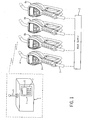
- Fig. 1 is a schematic diagram of the RF networked system incorporating the control station and several handheld metering devices.
- Fig. 2 is a perspective view of a device that incorporates the present invention
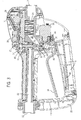
- Fig. 3 is a sectional view of the device of Fig. 2;
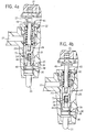
- Figs. 4a and 4b are detail views of the manual actuator and valve spool in the closed position and open position, respectively.
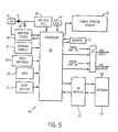
- Fig. 5 is a block diagram of the electrical system in the device of Figs. 2 and 3;
- Fig. 6 is a flow chart of the operation of the handheld metering device and control station.
- the dispensing system comprises a master control station 1 which is communicatively coupled to one or more handheld metering device 8.
- the metering devices 8 are each coupled to a bulk supply 2 by respective hoses 3.
- the bulk supply 2 supplies an oil, grease, or other lubricant to the metering device 8, and each metering device 8 selectively supplies the lubricant to a vehicle, tank, or container (not shown) through a spout 4.
- the master control station 1 includes a user interface 5 comprising a display 6 and an input device such as a plurality of keys 7.
- the control station 1 further includes a transmitter and receiver (not shown) and an associated antenna 9, which are communicatively coupled to the metering devices 8 through a communications network, which is preferably a low power wireless radio frequency link. It will be apparent that other wireless and wired communications networks can also be used.
- the amount of lubricant to be dispensed from each of the dispensing apparatuses 8 can be entered into a dispensing or batch program in the control station 1 through the user interface 5.
- the control station 1 communicates program information, including the preset amount of lubricant to be dispensed, to the dispensing units 8 through the network communication link.
- programs for each metering device 8 can be entered through programming keys 20 connected to the dispensing apparatus 8, as will be described more fully below.
- the dispensing program is controlled by a combination of manual inputs provided at the metering device 8 and through commands transmitted from the control station 1. These commands can include, for example, enable dispensing signals, start and stop dispensing signals, interrupt signals, reset signals, and meter start and stop signals.
- Other status data and commands can be communicated between the control station 1 and metering device 8, as described below.
- the metering device 8 of the present invention includes a casing 10, primarily of molded plastic material, except for an exposed metal band, which is an outside edge of a metal band housing 11.
- the casing 10 includes a head portion 12, a rounded handle 13 extending from the head portion 12, and a trigger guard portion 15 which extends from the head portion 12 and connects to a distal end of the handle 13.
- the device includes a manual lever 14 which, when squeezed against the handle 13 to further operate a valve (not shown in Fig. 2) opens and closes to control the flow of liquid.
- the liquid enters through inlet port 16 and exits through outlet port 17 (Fig. 3).
- Chevron-shaped treads or projections 13a are spaced along the handle 13 to provide for a better grip.
- the metering device 8 also includes a bezel portion 18 which fits around a user interface which can comprise a visual display 19 and a group of six programming keys 20 and one manual stop button 21.
- the manual stop button 21 provides an electrical signal to the control circuit 40 (Fig. 5) to close the valve and shut off liquid flow, in a manner described below.
- lubricating liquid flows into inlet port 16 and through supply passage 22 to a valve chamber 23.
- a valve member assembly 24 is arranged vertically in a valve seat for movement up and down to control liquid flow through the valve chamber 23.
- a second, inclined, supply passage 25 connects to a metering chamber in which two eccentric metering gears 26 turn in response to liquid flow. The liquid flows through metering gears 26 and out of the outlet port 17.
- the valve member assembly 24 is a multi-piece assmembly preferably comprising three parts, which are hereafter referred to as a start actuator 46, a stop actuator 45, and a valve member 73. Each of these parts will be described more fully below.
- the start actuator 46 is moveably coupled inside the valve member 73, and includes a push rod 33, first and second recesses 35 and 39, and a spring 48.
- the recesses 35 and 39 are sized and dimensioned to receive a latching pin 38 which is selectively activated by the electrical latching solenoid 36 for latching the valve member 73 in either an open or locked closed position as described below.
- the push rod 33 is disposed to be activated by the lever 14, and the spring 48 provides a return function, as well as manual feedback to an operator activating the lever 14 as described below.
- the stop actuator 45 includes a flange 49 and a return spring 32.
- the flange 49 activates a sensing switch 37, thereby providing an indication to the circuit board 27 that the valve member assembly 24 is open and can be latched in the open position, as described below.
- the return spring 32 causes the flange 49 to deactivate the sensing switch 37, thereby providing a signal to the circuit board 27 that the valve member assembly 24 is no longer in the open position.
- An electronic circuit board 27 is installed under the display 19, programming keys 20, and stop button 21 of the head portion 12 of the casing 10.
- a large capacitor 28 is mounted on the circuit board 27 along with a microelectronic processor 29, to one or more reed switch 30, to a display 19 and to other components to be described below.
- a radio board 43 including a receiver and a transmitter circuit for radio frequency (RF) communication with the master control station 1 is located in the trigger guard portion 15, along with an associated antenna 44.
- Power for the electronic circuit board 27, radio board 43, antenna board 44, and other circuitry is provided by four AA-sized batteries 31, also located within the trigger guard portion 15 of the casing 10.
- the radio board 43 is further electrically coupled to the electronic circuit board 27, wherein programs, commands and delivery status data can be transmitted to and received from the processor 29 and associated memory components, as described below.
- the processor 29 executes a control program stored in memory to count metering pulses generated by gears 26 and sensed through the reed switches 30 to units of flow and displays the value on display 19.
- the display 19 is capable of showing flow parameters, including for example, total volume and re-settable total.
- the metering gears 26 include permanent magnets (not shown). As the gears 26 and magnets rotate, they cause reed switches 30 to open and close due to the change in polarity of the magnetic field generated by the permanent magnets. The electrical pulses generated by the reed switches 30 are communicated to the processor 29 located on circuit board 27.
- the metering device 8 can be held in three different states, depending on the position of the latching pin 38. These states are: a locked open state, wherein the valve member assembly 24 is latched open by the latching pin 38; a locked closed state, wherein the valve member 24 is "locked out", or held closed by the latching pin 38; and a normally-closed manual state, wherein the latching pin 38 is not engaged and the lever 14 can be manually activated to open the valve and provide lubricant flow from the inlet 16 to the outlet 17. Activation of the electrically operable latching mechanism 36 to extend or retract the latching pin 38 into receiving recess 35 or 39 therefore determines the state of the metering device 8, as described below.
- valve member assembly 24 is forced closed by the spring 32 until the lever 14 is activated.
- squeezing the lever 14 towards the handle 13 causes the lever 14 to contact and move the push rod 33 of the start actuator 46, causing valve member 73 to be lifted upward to a position in which valve chamber 23 communicates with supply passage 22.
- Valve chamber 23 is also in communication with supply passage 25, to complete a flow path for the liquid from inlet 16 to gears 26 and eventually to outlet 17.
- the metering device 8 is shown in the locked closed state.
- the latching solenoid 36 is activated to extend the latching pin 38 into the recess 39, preventing movement of the valve member 73 such that the valve 23, 24 is maintained in a closed position, preventing the flow of fluid through the supply passages 22 and 25.
- the recess 39 is dimensioned to include a small amount of additional space or "play” wherein the start actuator 46 can be moved slightly even when the latching pin 38 is in the recess 39.
- the start actuator 46 contacts the latching pin 38 before the valve member assembly 24 can be opened, thereby preventing any flow of fluid or "leak through” to occur through the valve 24.
- the spring 48 provides a reactive force opposing the activation of the lever 14 which helps to prevent the operator from overstressing the lever, and therefore prevents potential damage to the metering device 8.
- the metering device 8 is shown in the open position.
- the latching solenoid 36 is activated to extend the latching pin 38 into the latching recess 35.
- the valve 23, 24 is held in the open position, allowing the flow of fluid through the supply passages 22 and 25.
- the valve member assembly 24 is open, the metering gears 26 rotate at a rate proportional to the flow rate of the liquid, and fluid flow can be metered as described above.
- an electronic control circuit 40 mounted on circuit board 27 includes processor 29, which in the preferred embodiment, is provided by an MSP 430 microelectronic processor 29 with on-board memory available from Texas Instruments, Inc.
- a control program of instructions is stored in the on-board memory to carry out the control functions described herein.
- a EEPROM 41 is also connected to the processor 29 to store user settings and batch histories.
- a crystal oscillator circuit 42 provides timing signals for driving the processor 29.
- the processor 29 reads inputs from programming keys 20 and transmits data to display 19.
- the processor 29 also transmits control signals to enable latching the solenoid 36 (SOL. LATCH) and to enable unlatching the solenoid 36 (SOL. UNLATCH). These are coupled to the solenoid 36 through power transistor circuits 47.
- the processor 29 also senses input signals from reed switches 30 and trigger sensing switch 27.
- the processor 29 senses the voltage of the batteries 31 through a battery check circuit 50.
- the batteries supply six dc volts unregulated power to a voltage regulator circuit 49, which supplies 3.3 dc volts power to the other circuitry in the control circuit 40.
- the capacitor 28 is connected through a diode 51 to the batteries 31 to be charged by the batteries 31 to six dc volts unregulated power.
- the circuit board 27 and associated processor 29 are further coupled to the radio board 43 and associated antenna 44 through a bidirectional link.
- the processor 29 receives command signals and data from the control station 1, and transmits command signals, status information and data to the control station.
- the circuit board 27 and associated processor 29 receive input signals from the programming keys 20 and stop button 21.
- the processor 29 provides a signal to the latching solenoid 36 to unlatch the solenoid and close the valve assembly 24.
- the programming keys 20 can be used to program "batches", or the amount of fluid to be dispensed when the metering device 8 is used in a manual mode, and can also be used to supply a "reset" signal.
- the reset signal is received by the circuit board 27 and can be transmitted to the control station 1 through the radio board 43.
- the metering device 8 is controlled by the control circuit 40 and the control station 1 to dispense preset amounts or batches of lubricants.
- the control station 1 provides command data to the control circuit 40 which can include, for example, start commands, stop commands, interrupt commands, and programs providing an amount of a lubricant to be dispensed.
- the metering device 8 receives commands from the control station 1, and controls the opening and closing of the valve member assembly 24, as well as metering functions, and manual operator signals.
- a flow chart illustrating the operation of the metering device 8 in dispensing a lubricant in accordance with the present invention is shown.
- the control station 1 transmits data including a preset amount to be dispensed by the metering device 8 through antenna 9 to antenna board 44 and the associated radio board 43 in the metering device 8.
- the received preset amount can be transmitted to the processor 29 which stores the dispensing data in memory.
- the processor 29 signals the power transistors 47 to unlatch the latching solenoid 36 to remove the latching pin 38 from the locked closed position, wherein the valve is latched closed.
- the processor 29 then monitors the trigger sensing switch 27 to determine whether the lever 14 has been manually activated.
- step 59 when the control circuit 40 senses that the lever 14 has been activated and that the valve member assembly 24 is open, the processor 29 latches the latching solenoid 36 in the open position causing the pin 38 to extend into the recess 35, thereby latching the valve member 73 in the open position wherein the fluid can flow from the supply passage 22 through the valve member 73 to the supply passage 25 and therefore out the outlet 17.
- the processor 29 continually monitors the flow through the meter 10 as described above.
- the processor 29 also continually monitors the radio board 43 for transmissions from the control station 1, which can transmit a signal to the metering device to interrupt or halt the dispensing of fluid from the metering device 8.
- step 61 When the batch is done, as shown in step 61, the preset amount has been dispensed. At this point, the processor 29 energizes the solenoid 36 through a release signal provided to the power transistor circuits 47, causing the pin 38 to retract. As the pin 38 retracts, the valve member assembly 24 moves to the manual position as described with reference to Fig. 3 above, aided by the spring 32. In the manual position, the valve can be temporarily activated by the lever 14 to allow a user to pump additional fluid, or "top off" the tank or container being filled (step 62). After the selected amount of fluid is dispensed, the user manually activates a reset switch, step 63, which is detected by the processor 29 and through the trigger sensing switch 27.
- the metering device 8 provides a signal to the control station 1 through the radio board 43 and associated antenna 44.
- the control station receives the reset signal it provides a disable signal to the control circuit 40 through the radio board 43 to disable the valve by energizing the solenoid 36, moving the latching pin 38 into the recess 39, and therefore locking the valve member assembly 24 in the closed position.
- the metering device 8 remains disabled until a new program is transmitted from the control station 1 (step 55), and the metering device 8 is then returned to the manual state, waiting for the lever 14 to again be manually activated.
- the solenoid 36 can latch the valve 24 in the closed position of Fig. 3b by again energizing the solenoid 36 to activate the latching pin 38.
- the device is held in the closed position until the operator enters a reset 63 through the programming keys 20 or a dedicated key located on the user interface of the metering device 8.
- the reset provides an indication to the control station 1 that the metering device 8 is ready to receive a new preset amount, which is transmitted to the radio board 43 to begin the process again at step 55.
- the metering device 8 is controlled by the control circuit 40 and the control station 1 to dispense preset amounts or batches of lubricants.
- the control station 1 provides commands and data to the control circuit 40 which can include, for example, start commands, stop commands, interrupt commands, and data providing an amount of a lubricant to be dispensed.
- the metering device 8 receives commands and data from the control station 1, and controls the opening and closing of the valve member assembly 24, as well as metering functions, and manual operator signals.
Landscapes
- Physics & Mathematics (AREA)
- Engineering & Computer Science (AREA)
- Mechanical Engineering (AREA)
- Fluid Mechanics (AREA)
- General Physics & Mathematics (AREA)
- Mathematical Physics (AREA)
- Theoretical Computer Science (AREA)
- Electromagnetism (AREA)
- Computer Networks & Wireless Communication (AREA)
- Loading And Unloading Of Fuel Tanks Or Ships (AREA)
- Infusion, Injection, And Reservoir Apparatuses (AREA)
- Electrical Control Of Air Or Fuel Supplied To Internal-Combustion Engine (AREA)
- Frying-Pans Or Fryers (AREA)
- Confectionery (AREA)
- Pinball Game Machines (AREA)
- Lubricants (AREA)
Applications Claiming Priority (2)
| Application Number | Priority Date | Filing Date | Title |
|---|---|---|---|
| US09/969,193 US6659306B2 (en) | 2001-10-02 | 2001-10-02 | Electronic lube gun with master station control |
| EP02775749A EP1440033B1 (fr) | 2001-10-02 | 2002-09-03 | Pistolet doseur de lubrifiant electronique avec station centrale de commande |
Related Parent Applications (1)
| Application Number | Title | Priority Date | Filing Date |
|---|---|---|---|
| EP02775749A Division EP1440033B1 (fr) | 2001-10-02 | 2002-09-03 | Pistolet doseur de lubrifiant electronique avec station centrale de commande |
Publications (2)
| Publication Number | Publication Date |
|---|---|
| EP1637497A1 true EP1637497A1 (fr) | 2006-03-22 |
| EP1637497B1 EP1637497B1 (fr) | 2007-07-18 |
Family
ID=25515289
Family Applications (2)
| Application Number | Title | Priority Date | Filing Date |
|---|---|---|---|
| EP05024363A Expired - Lifetime EP1637497B1 (fr) | 2001-10-02 | 2002-09-03 | Pistolet de remplissage ayant un dispositif de pilotage |
| EP02775749A Expired - Lifetime EP1440033B1 (fr) | 2001-10-02 | 2002-09-03 | Pistolet doseur de lubrifiant electronique avec station centrale de commande |
Family Applications After (1)
| Application Number | Title | Priority Date | Filing Date |
|---|---|---|---|
| EP02775749A Expired - Lifetime EP1440033B1 (fr) | 2001-10-02 | 2002-09-03 | Pistolet doseur de lubrifiant electronique avec station centrale de commande |
Country Status (12)
| Country | Link |
|---|---|
| US (1) | US6659306B2 (fr) |
| EP (2) | EP1637497B1 (fr) |
| JP (1) | JP2005537189A (fr) |
| KR (1) | KR101030512B1 (fr) |
| CN (2) | CN1248956C (fr) |
| AT (2) | ATE367361T1 (fr) |
| AU (1) | AU2002341599B2 (fr) |
| CA (1) | CA2462107C (fr) |
| DE (2) | DE60213838T2 (fr) |
| ES (2) | ES2271339T3 (fr) |
| MX (1) | MXPA04002146A (fr) |
| WO (1) | WO2003029135A1 (fr) |
Cited By (2)
| Publication number | Priority date | Publication date | Assignee | Title |
|---|---|---|---|---|
| WO2008114174A3 (fr) * | 2007-03-20 | 2008-12-31 | Identitag Pty Ltd | Appareil de commande de distribution de liquides |
| EP3719455A1 (fr) * | 2019-04-05 | 2020-10-07 | Collomix GmbH | Dispositif de dosage permettant de distribuer une quantité de liquide prédéterminée, en particulier une quantité d'eau prédéterminée |
Families Citing this family (29)
| Publication number | Priority date | Publication date | Assignee | Title |
|---|---|---|---|---|
| TWI294503B (en) * | 2002-09-20 | 2008-03-11 | Graco Minnesota Inc | Self contained lubricant dispenser |
| US8424722B2 (en) * | 2002-09-20 | 2013-04-23 | Graco Minnesota Inc. | Self contained lubricant dispenser |
| US20080203726A1 (en) * | 2005-07-28 | 2008-08-28 | Breeser David L | Data Communication System Embedded In A Fluid Dispensing Line With Limited Travel Swivel |
| US20070260471A1 (en) * | 2006-05-02 | 2007-11-08 | Lincoln Industrial Corporation | Interface between dealer management system and fluid delivery system |
| US20080303691A1 (en) * | 2007-06-07 | 2008-12-11 | Lincoln Industrial Corporation | Hybrid automotive fluid dispensing system |
| US8240507B2 (en) * | 2008-06-20 | 2012-08-14 | Graco Minnesota Inc. | Seal-retaining valve for fluid metering device |
| US8215522B2 (en) * | 2008-06-20 | 2012-07-10 | Graco Minnesota Inc. | Trigger release mechanism for fluid metering device |
| CA2676545A1 (fr) * | 2009-04-30 | 2010-10-30 | Castrol Limited | Appareil de distribution des fluides d'un vehicule et methode d'utilisation connexe |
| CA2707295C (fr) * | 2009-06-12 | 2019-06-18 | Automatic Bar Controls, Inc. | Systeme de distribution de fluide ecologique |
| BR112012023070A2 (pt) * | 2010-03-18 | 2019-09-24 | Axia Acquisition Corp | ajuste de fluxo de bomba em ferramenta. |
| EP2505547B1 (fr) * | 2011-03-30 | 2016-08-10 | Pavanis Holding B.V. | Carter avec écran pour une buse de distribution de carburant |
| EP2574595A1 (fr) * | 2011-09-30 | 2013-04-03 | Elaflex Hiby Tanktechnik GmbH & Co. | Buse de distribution |
| US9051164B2 (en) * | 2011-09-30 | 2015-06-09 | Elaflex Hiby Tanktechnik Gmbh & Co. Kg | Dispensing valve |
| JP2014077706A (ja) * | 2012-10-11 | 2014-05-01 | Tatsuno Corp | 可搬式流量計 |
| WO2015053676A1 (fr) | 2013-10-10 | 2015-04-16 | Ngc Innovation Ab | Système de verrouillage de distributeur de carburant |
| DE102014004822A1 (de) * | 2014-03-29 | 2015-10-01 | Dürr Somac GmbH | Befülladapter |
| CN106838272A (zh) * | 2015-12-04 | 2017-06-13 | 重庆银聪科技有限公司 | 一种齿轮箱润滑油自动添加装置 |
| US10376911B2 (en) * | 2017-01-05 | 2019-08-13 | Graco Minnesota Inc. | Handheld fluid meter |
| WO2018175789A1 (fr) | 2017-03-22 | 2018-09-27 | Graco Minnesota Inc. | Autorisation de compteur de distribution de fluide |
| US11292710B2 (en) | 2017-09-15 | 2022-04-05 | Graco Minnesota Inc. | Fluid management system and fluid dispenser |
| EP4512768A3 (fr) * | 2017-09-15 | 2025-04-30 | Graco Minnesota Inc. | Dispositif de mesure de distribution pour distribution de fluide |
| US12030770B2 (en) | 2017-09-15 | 2024-07-09 | Graco Minnesota Inc. | Fluid management system and fluid dispenser |
| JP7254026B2 (ja) | 2017-10-02 | 2023-04-07 | グラコ ミネソタ インコーポレーテッド | 液体管理コントローラ |
| KR102629383B1 (ko) * | 2017-10-10 | 2024-01-29 | 그라코 미네소타 인크. | 유체 분배 계량기 허가 |
| US11733125B2 (en) | 2020-12-22 | 2023-08-22 | U.E. Systems, Inc. | Auto-adjusting analog ultrasonic sensor |
| US12578308B2 (en) | 2020-12-22 | 2026-03-17 | U.E. Systems, Inc. | Method and apparatus for detecting an initial lubrication of a moving component |
| US12007360B2 (en) * | 2020-12-22 | 2024-06-11 | U.E. Systems, Inc. | Globally-based automatic lubrication system |
| US12129166B2 (en) | 2021-06-14 | 2024-10-29 | Graco Minnesota Inc. | Fluid dispenser system |
| EP4655238A2 (fr) | 2023-01-27 | 2025-12-03 | Vgp Ipco Llc | Récipient réutilisable ou reremplissable pour distribuer de l'huile de moteur |
Citations (3)
| Publication number | Priority date | Publication date | Assignee | Title |
|---|---|---|---|---|
| US5249129A (en) * | 1991-02-22 | 1993-09-28 | Alain Lamoureux | Method and system for dispensing precise amount of fluid with automatic set reset |
| US5433342A (en) * | 1991-12-20 | 1995-07-18 | Establissements Luro (S.A.R.L.) | Method and apparatus for supplying preset quantities of liquids |
| US5867403A (en) * | 1995-10-11 | 1999-02-02 | Universal Epsco, Inc. | Fuel dispenser |
Family Cites Families (11)
| Publication number | Priority date | Publication date | Assignee | Title |
|---|---|---|---|---|
| JPH0617157B2 (ja) * | 1986-01-31 | 1994-03-09 | 株式会社タツノ・メカトロニクス | 給油ノズル |
| CA1325412C (fr) | 1987-07-28 | 1993-12-21 | Vernon K. Quarve | Unite de distribution et de mesurage alimente par pile |
| US5184309A (en) * | 1990-03-20 | 1993-02-02 | Saber Equipment Corp. | Fluid dispensing nozzle including in line flow meter and data processing unit |
| JPH0848396A (ja) * | 1994-08-05 | 1996-02-20 | Tatsuno Co Ltd | 給油ノズル |
| US5612890A (en) | 1995-05-19 | 1997-03-18 | F C Systems, Inc. | System and method for controlling product dispensation utilizing metered valve apparatus and electronic interconnection map corresponding to plumbing interconnections |
| USD382500S (en) | 1995-12-19 | 1997-08-19 | Graco Inc. | Dispensing meter |
| US5941418A (en) | 1995-12-29 | 1999-08-24 | Graco Inc | Multiple fluid dispensing system |
| TW479675U (en) * | 1996-02-01 | 2002-03-11 | Graco Inc | Preset fluid dispensing meter |
| US6571151B1 (en) * | 1998-03-06 | 2003-05-27 | Russel Dean Leatherman | Wireless nozzle interface for a fuel dispenser |
| JP2000168899A (ja) * | 1998-11-30 | 2000-06-20 | Tokico Ltd | 給油装置 |
| US6443328B1 (en) * | 2000-06-16 | 2002-09-03 | Badger Meter, Inc. | Electronic lube gun with low battery protection |
-
2001
- 2001-10-02 US US09/969,193 patent/US6659306B2/en not_active Expired - Lifetime
-
2002
- 2002-09-03 JP JP2003532400A patent/JP2005537189A/ja active Pending
- 2002-09-03 ES ES02775749T patent/ES2271339T3/es not_active Expired - Lifetime
- 2002-09-03 CA CA2462107A patent/CA2462107C/fr not_active Expired - Fee Related
- 2002-09-03 DE DE60213838T patent/DE60213838T2/de not_active Expired - Lifetime
- 2002-09-03 AU AU2002341599A patent/AU2002341599B2/en not_active Ceased
- 2002-09-03 AT AT05024363T patent/ATE367361T1/de not_active IP Right Cessation
- 2002-09-03 KR KR1020047003612A patent/KR101030512B1/ko not_active Expired - Fee Related
- 2002-09-03 EP EP05024363A patent/EP1637497B1/fr not_active Expired - Lifetime
- 2002-09-03 EP EP02775749A patent/EP1440033B1/fr not_active Expired - Lifetime
- 2002-09-03 MX MXPA04002146A patent/MXPA04002146A/es active IP Right Grant
- 2002-09-03 CN CNB028175522A patent/CN1248956C/zh not_active Expired - Fee Related
- 2002-09-03 DE DE60221303T patent/DE60221303T2/de not_active Expired - Lifetime
- 2002-09-03 CN CNB2005101180106A patent/CN100551814C/zh not_active Expired - Fee Related
- 2002-09-03 ES ES05024363T patent/ES2288282T3/es not_active Expired - Lifetime
- 2002-09-03 AT AT02775749T patent/ATE335707T1/de not_active IP Right Cessation
- 2002-09-03 WO PCT/US2002/028177 patent/WO2003029135A1/fr not_active Ceased
Patent Citations (3)
| Publication number | Priority date | Publication date | Assignee | Title |
|---|---|---|---|---|
| US5249129A (en) * | 1991-02-22 | 1993-09-28 | Alain Lamoureux | Method and system for dispensing precise amount of fluid with automatic set reset |
| US5433342A (en) * | 1991-12-20 | 1995-07-18 | Establissements Luro (S.A.R.L.) | Method and apparatus for supplying preset quantities of liquids |
| US5867403A (en) * | 1995-10-11 | 1999-02-02 | Universal Epsco, Inc. | Fuel dispenser |
Cited By (2)
| Publication number | Priority date | Publication date | Assignee | Title |
|---|---|---|---|---|
| WO2008114174A3 (fr) * | 2007-03-20 | 2008-12-31 | Identitag Pty Ltd | Appareil de commande de distribution de liquides |
| EP3719455A1 (fr) * | 2019-04-05 | 2020-10-07 | Collomix GmbH | Dispositif de dosage permettant de distribuer une quantité de liquide prédéterminée, en particulier une quantité d'eau prédéterminée |
Also Published As
| Publication number | Publication date |
|---|---|
| HK1085991A1 (zh) | 2006-09-08 |
| EP1440033B1 (fr) | 2006-08-09 |
| CA2462107C (fr) | 2012-02-07 |
| DE60213838D1 (de) | 2006-09-21 |
| JP2005537189A (ja) | 2005-12-08 |
| DE60213838T2 (de) | 2007-03-08 |
| DE60221303T2 (de) | 2008-04-03 |
| HK1071561A1 (en) | 2005-07-22 |
| WO2003029135A1 (fr) | 2003-04-10 |
| MXPA04002146A (es) | 2004-07-23 |
| US6659306B2 (en) | 2003-12-09 |
| ATE335707T1 (de) | 2006-09-15 |
| ATE367361T1 (de) | 2007-08-15 |
| CN1248956C (zh) | 2006-04-05 |
| EP1637497B1 (fr) | 2007-07-18 |
| CN1757590A (zh) | 2006-04-12 |
| US20030062380A1 (en) | 2003-04-03 |
| KR20040044896A (ko) | 2004-05-31 |
| CA2462107A1 (fr) | 2003-04-10 |
| ES2271339T3 (es) | 2007-04-16 |
| CN1553879A (zh) | 2004-12-08 |
| EP1440033A1 (fr) | 2004-07-28 |
| AU2002341599B2 (en) | 2007-06-21 |
| CN100551814C (zh) | 2009-10-21 |
| KR101030512B1 (ko) | 2011-04-26 |
| DE60221303D1 (de) | 2007-08-30 |
| ES2288282T3 (es) | 2008-01-01 |
Similar Documents
| Publication | Publication Date | Title |
|---|---|---|
| EP1637497B1 (fr) | Pistolet de remplissage ayant un dispositif de pilotage | |
| AU2002341599A1 (en) | Electronic lube gun with master station control | |
| CA2406617C (fr) | Pistolet de graissage electronique dote d'une protection de pile faible | |
| AU2001259502A1 (en) | Electronic lube gun with low battery protection | |
| US4930665A (en) | Liquid dispensing system with electronically controlled valve remote from nozzle | |
| US4934565A (en) | Liquid dispensing system with electronically controlled valve remote from nozzle | |
| US6203183B1 (en) | Multiple component in-line paint mixing system | |
| US5887975A (en) | Multiple component in-line paint mixing system | |
| US4522237A (en) | Apparatus for dispensing liquids | |
| KR101653420B1 (ko) | 유체 측정 장치용 트리거 릴리즈 메커니즘 | |
| CN108279049B (zh) | 手持式流体计量仪 | |
| EP3556726A1 (fr) | Appareil de distribution et son procédé d'utilisation | |
| HK1085991B (en) | Wireless networked system for dispensing a lubricating fluid | |
| HK1071561B (en) | Method and device for dispensing a lubrication fluid | |
| JPH1191899A (ja) | 給油装置 | |
| CN100540454C (zh) | 用于分配的膜和电磁控制阀 | |
| NL2008805C2 (en) | Device and method for delivering windscreen washer fluid to a vehicle. | |
| EP0360464A2 (fr) | Système distributeur de liquide | |
| WO2005020703A1 (fr) | Distributeur |
Legal Events
| Date | Code | Title | Description |
|---|---|---|---|
| PUAI | Public reference made under article 153(3) epc to a published international application that has entered the european phase |
Free format text: ORIGINAL CODE: 0009012 |
|
| AC | Divisional application: reference to earlier application |
Ref document number: 1440033 Country of ref document: EP Kind code of ref document: P |
|
| AK | Designated contracting states |
Kind code of ref document: A1 Designated state(s): AT BE BG CH CY CZ DE DK EE ES FI FR GB GR IE IT LI LU MC NL PT SE SK TR |
|
| 17P | Request for examination filed |
Effective date: 20060624 |
|
| AKX | Designation fees paid |
Designated state(s): AT BE BG CH CY CZ DE DK EE ES FI FR GB GR IE IT LI LU MC NL PT SE SK TR |
|
| GRAP | Despatch of communication of intention to grant a patent |
Free format text: ORIGINAL CODE: EPIDOSNIGR1 |
|
| GRAS | Grant fee paid |
Free format text: ORIGINAL CODE: EPIDOSNIGR3 |
|
| GRAA | (expected) grant |
Free format text: ORIGINAL CODE: 0009210 |
|
| AC | Divisional application: reference to earlier application |
Ref document number: 1440033 Country of ref document: EP Kind code of ref document: P |
|
| AK | Designated contracting states |
Kind code of ref document: B1 Designated state(s): AT BE BG CH CY CZ DE DK EE ES FI FR GB GR IE IT LI LU MC NL PT SE SK TR |
|
| REG | Reference to a national code |
Ref country code: GB Ref legal event code: FG4D |
|
| REG | Reference to a national code |
Ref country code: CH Ref legal event code: EP |
|
| REF | Corresponds to: |
Ref document number: 60221303 Country of ref document: DE Date of ref document: 20070830 Kind code of ref document: P |
|
| REG | Reference to a national code |
Ref country code: IE Ref legal event code: FG4D |
|
| REG | Reference to a national code |
Ref country code: ES Ref legal event code: FG2A Ref document number: 2288282 Country of ref document: ES Kind code of ref document: T3 |
|
| ET | Fr: translation filed | ||
| PG25 | Lapsed in a contracting state [announced via postgrant information from national office to epo] |
Ref country code: PT Free format text: LAPSE BECAUSE OF FAILURE TO SUBMIT A TRANSLATION OF THE DESCRIPTION OR TO PAY THE FEE WITHIN THE PRESCRIBED TIME-LIMIT Effective date: 20071218 Ref country code: FI Free format text: LAPSE BECAUSE OF FAILURE TO SUBMIT A TRANSLATION OF THE DESCRIPTION OR TO PAY THE FEE WITHIN THE PRESCRIBED TIME-LIMIT Effective date: 20070718 Ref country code: BG Free format text: LAPSE BECAUSE OF FAILURE TO SUBMIT A TRANSLATION OF THE DESCRIPTION OR TO PAY THE FEE WITHIN THE PRESCRIBED TIME-LIMIT Effective date: 20071018 Ref country code: NL Free format text: LAPSE BECAUSE OF FAILURE TO SUBMIT A TRANSLATION OF THE DESCRIPTION OR TO PAY THE FEE WITHIN THE PRESCRIBED TIME-LIMIT Effective date: 20070718 |
|
| REG | Reference to a national code |
Ref country code: CH Ref legal event code: PL |
|
| NLV1 | Nl: lapsed or annulled due to failure to fulfill the requirements of art. 29p and 29m of the patents act | ||
| PG25 | Lapsed in a contracting state [announced via postgrant information from national office to epo] |
Ref country code: CH Free format text: LAPSE BECAUSE OF FAILURE TO SUBMIT A TRANSLATION OF THE DESCRIPTION OR TO PAY THE FEE WITHIN THE PRESCRIBED TIME-LIMIT Effective date: 20070718 Ref country code: LI Free format text: LAPSE BECAUSE OF FAILURE TO SUBMIT A TRANSLATION OF THE DESCRIPTION OR TO PAY THE FEE WITHIN THE PRESCRIBED TIME-LIMIT Effective date: 20070718 Ref country code: AT Free format text: LAPSE BECAUSE OF FAILURE TO SUBMIT A TRANSLATION OF THE DESCRIPTION OR TO PAY THE FEE WITHIN THE PRESCRIBED TIME-LIMIT Effective date: 20070718 |
|
| PG25 | Lapsed in a contracting state [announced via postgrant information from national office to epo] |
Ref country code: BE Free format text: LAPSE BECAUSE OF FAILURE TO SUBMIT A TRANSLATION OF THE DESCRIPTION OR TO PAY THE FEE WITHIN THE PRESCRIBED TIME-LIMIT Effective date: 20070718 |
|
| PG25 | Lapsed in a contracting state [announced via postgrant information from national office to epo] |
Ref country code: DK Free format text: LAPSE BECAUSE OF FAILURE TO SUBMIT A TRANSLATION OF THE DESCRIPTION OR TO PAY THE FEE WITHIN THE PRESCRIBED TIME-LIMIT Effective date: 20070718 Ref country code: MC Free format text: LAPSE BECAUSE OF NON-PAYMENT OF DUE FEES Effective date: 20070930 Ref country code: GR Free format text: LAPSE BECAUSE OF FAILURE TO SUBMIT A TRANSLATION OF THE DESCRIPTION OR TO PAY THE FEE WITHIN THE PRESCRIBED TIME-LIMIT Effective date: 20071019 |
|
| PLBE | No opposition filed within time limit |
Free format text: ORIGINAL CODE: 0009261 |
|
| STAA | Information on the status of an ep patent application or granted ep patent |
Free format text: STATUS: NO OPPOSITION FILED WITHIN TIME LIMIT |
|
| PG25 | Lapsed in a contracting state [announced via postgrant information from national office to epo] |
Ref country code: SK Free format text: LAPSE BECAUSE OF FAILURE TO SUBMIT A TRANSLATION OF THE DESCRIPTION OR TO PAY THE FEE WITHIN THE PRESCRIBED TIME-LIMIT Effective date: 20070718 Ref country code: CZ Free format text: LAPSE BECAUSE OF FAILURE TO SUBMIT A TRANSLATION OF THE DESCRIPTION OR TO PAY THE FEE WITHIN THE PRESCRIBED TIME-LIMIT Effective date: 20070718 |
|
| 26N | No opposition filed |
Effective date: 20080421 |
|
| PG25 | Lapsed in a contracting state [announced via postgrant information from national office to epo] |
Ref country code: SE Free format text: LAPSE BECAUSE OF FAILURE TO SUBMIT A TRANSLATION OF THE DESCRIPTION OR TO PAY THE FEE WITHIN THE PRESCRIBED TIME-LIMIT Effective date: 20071018 |
|
| PG25 | Lapsed in a contracting state [announced via postgrant information from national office to epo] |
Ref country code: IE Free format text: LAPSE BECAUSE OF NON-PAYMENT OF DUE FEES Effective date: 20070903 |
|
| PG25 | Lapsed in a contracting state [announced via postgrant information from national office to epo] |
Ref country code: EE Free format text: LAPSE BECAUSE OF FAILURE TO SUBMIT A TRANSLATION OF THE DESCRIPTION OR TO PAY THE FEE WITHIN THE PRESCRIBED TIME-LIMIT Effective date: 20070718 |
|
| PG25 | Lapsed in a contracting state [announced via postgrant information from national office to epo] |
Ref country code: CY Free format text: LAPSE BECAUSE OF FAILURE TO SUBMIT A TRANSLATION OF THE DESCRIPTION OR TO PAY THE FEE WITHIN THE PRESCRIBED TIME-LIMIT Effective date: 20070718 |
|
| PG25 | Lapsed in a contracting state [announced via postgrant information from national office to epo] |
Ref country code: LU Free format text: LAPSE BECAUSE OF NON-PAYMENT OF DUE FEES Effective date: 20070903 |
|
| PG25 | Lapsed in a contracting state [announced via postgrant information from national office to epo] |
Ref country code: TR Free format text: LAPSE BECAUSE OF FAILURE TO SUBMIT A TRANSLATION OF THE DESCRIPTION OR TO PAY THE FEE WITHIN THE PRESCRIBED TIME-LIMIT Effective date: 20070718 |
|
| REG | Reference to a national code |
Ref country code: FR Ref legal event code: PLFP Year of fee payment: 14 |
|
| REG | Reference to a national code |
Ref country code: FR Ref legal event code: PLFP Year of fee payment: 15 |
|
| REG | Reference to a national code |
Ref country code: FR Ref legal event code: PLFP Year of fee payment: 16 |
|
| REG | Reference to a national code |
Ref country code: FR Ref legal event code: PLFP Year of fee payment: 17 |
|
| PGFP | Annual fee paid to national office [announced via postgrant information from national office to epo] |
Ref country code: FR Payment date: 20180712 Year of fee payment: 17 Ref country code: IT Payment date: 20180919 Year of fee payment: 17 |
|
| PGFP | Annual fee paid to national office [announced via postgrant information from national office to epo] |
Ref country code: GB Payment date: 20180829 Year of fee payment: 17 |
|
| PGFP | Annual fee paid to national office [announced via postgrant information from national office to epo] |
Ref country code: ES Payment date: 20181001 Year of fee payment: 17 |
|
| PG25 | Lapsed in a contracting state [announced via postgrant information from national office to epo] |
Ref country code: IT Free format text: LAPSE BECAUSE OF NON-PAYMENT OF DUE FEES Effective date: 20190903 |
|
| GBPC | Gb: european patent ceased through non-payment of renewal fee |
Effective date: 20190903 |
|
| PG25 | Lapsed in a contracting state [announced via postgrant information from national office to epo] |
Ref country code: GB Free format text: LAPSE BECAUSE OF NON-PAYMENT OF DUE FEES Effective date: 20190903 Ref country code: FR Free format text: LAPSE BECAUSE OF NON-PAYMENT OF DUE FEES Effective date: 20190930 |
|
| REG | Reference to a national code |
Ref country code: ES Ref legal event code: FD2A Effective date: 20210127 |
|
| PG25 | Lapsed in a contracting state [announced via postgrant information from national office to epo] |
Ref country code: ES Free format text: LAPSE BECAUSE OF NON-PAYMENT OF DUE FEES Effective date: 20190904 |
|
| PGFP | Annual fee paid to national office [announced via postgrant information from national office to epo] |
Ref country code: DE Payment date: 20210929 Year of fee payment: 20 |
|
| REG | Reference to a national code |
Ref country code: DE Ref legal event code: R071 Ref document number: 60221303 Country of ref document: DE |