EP1643155A1 - Ressort combine - Google Patents
Ressort combine Download PDFInfo
- Publication number
- EP1643155A1 EP1643155A1 EP04738227A EP04738227A EP1643155A1 EP 1643155 A1 EP1643155 A1 EP 1643155A1 EP 04738227 A EP04738227 A EP 04738227A EP 04738227 A EP04738227 A EP 04738227A EP 1643155 A1 EP1643155 A1 EP 1643155A1
- Authority
- EP
- European Patent Office
- Prior art keywords
- spring
- damping
- damping body
- composite
- deformation
- Prior art date
- Legal status (The legal status is an assumption and is not a legal conclusion. Google has not performed a legal analysis and makes no representation as to the accuracy of the status listed.)
- Withdrawn
Links
Images


Classifications
-
- F—MECHANICAL ENGINEERING; LIGHTING; HEATING; WEAPONS; BLASTING
- F16—ENGINEERING ELEMENTS AND UNITS; GENERAL MEASURES FOR PRODUCING AND MAINTAINING EFFECTIVE FUNCTIONING OF MACHINES OR INSTALLATIONS; THERMAL INSULATION IN GENERAL
- F16F—SPRINGS; SHOCK-ABSORBERS; MEANS FOR DAMPING VIBRATION
- F16F3/00—Spring units consisting of several springs, e.g. for obtaining a desired spring characteristic
- F16F3/08—Spring units consisting of several springs, e.g. for obtaining a desired spring characteristic with springs made of a material having high internal friction, e.g. rubber
- F16F3/10—Spring units consisting of several springs, e.g. for obtaining a desired spring characteristic with springs made of a material having high internal friction, e.g. rubber combined with springs made of steel or other material having low internal friction
- F16F3/12—Spring units consisting of several springs, e.g. for obtaining a desired spring characteristic with springs made of a material having high internal friction, e.g. rubber combined with springs made of steel or other material having low internal friction the steel spring being in contact with the rubber spring
Definitions
- the invention relates to a spring.
- Usual springs are made of simple, elastic material whose damping is low, especially with springs made of metal.
- springs are sometimes sheathed in rubber tubing or a rubber layer is vulcanized onto the outside surface of the spring to increase cushioning.
- rubber is a visco-elastic material that has a certain damping effect in the high frequency range, for. B. in terms of vibrations and noise in the audio frequency range.
- the degree of damping is only 1% - 3%.
- the damping is even lower when rubber is connected in parallel to a spring.
- For many applications e.g. for vibration damping or vibration isolation of machinery and vehicles, where preferably a degree of attenuation between 10% and 30% is required, this attenuation is not sufficient.
- a separate damper is needed, which makes the structure complicated.
- the object of the invention is to eliminate the above-mentioned deficiencies and to provide a spring with integrated damping effect.
- the invention proposes a spring characterized in that the spring is combined with a damping body, the damping body being made of damping material which has a damping effect with respect to the movement of the spring.
- the damping material should have a high attenuation, being used as damping material in particular visco-elastic material with high attenuation or visco-plastic material, eg rubber with high damping, polyurethane with high damping or modified bitumen with high damping come into consideration.
- the material damping of such damping material can reach 30% - 50%.
- the loss factor of normal elastic material however, is only between 0.1% and 1% and the loss factor of conventional rubbers is about 1% -3%. It is further preferred if additives are contained in the damping material, which cause a higher deformation resistance, more internal friction and damping, such as carbon fiber, fiberglass and mica powder.
- At least a part of the spring should be embedded in the damping body.
- the above-mentioned damper body may be a solid cylinder or a hollow cylinder.
- the actual spring may according to the invention be any spring, e.g. a coil spring or a plate spring. If the spring is a coil spring, a cavity or a soft elastic material may be provided between the spring wires. If the spring is a disk spring, annular cavities or a soft elastic material may be provided in an annular manner between the spring disks and above and below the spring disks.
- thrust resistance body can be arranged with great rigidity around the damping body or introduced into the damping body.
- the thrust resistance bodies may complicate the deformation of the damping body and increase the shear deformation rate of the damping body.
- the so-called shear resistance body is a spiral ring or a sleeve.
- a layer of high strength elastic material is applied to the outer surface of the damping body.
- the spring with the High-damping material has a damping even when unloading, which hinders the return of the spring and the high-damping material.
- the strength of the high-damping material is normally lower than that of the self-base elastic material, so that the applied high-strength elastic outer layer is advantageous in recovering the damping material.
- the outer layer protects against damage, eg as a result of friction and / or shock.
- the damping material can be applied only to a part of the outer surface of the coil spring or the plate spring.
- at least one shear resistance layer with higher rigidity may be applied to the damping layer.
- a plurality of springs can be connected in series or in parallel.
- the composite spring itself comprises the actual spring and the damping body.
- the damping body deforms.
- the internal friction in the damping material thereby consumes the external energy, so that the deformation is hindered and vibrations are weakened.
- the structure-borne sound caused by the vibrations is reduced.
- damping material is used with high damping, so that a higher damping is achieved, as it is desirable for the vibration isolation of most machinery and vehicles. If a very high degree of damping is required, a smaller additional damping can be connected in parallel. Normally, however, an additional damping is not required, thereby simplifying the structure.
- the inventive design of the spring can dampen their self-resonant vibrations.
- Embodiment 1 of the invention consists of the coil spring 1 and the damping body 2, wherein the entire coil spring 1 is inserted into the cylindrical damping body 2.
- the damping body 2 consists of modified bitumen, which is a solid at normal temperature and behaves visco-plastic or visco-elastic. When the spring deforms under load, the damping body deforms at the same time. Because the damping material has a strong internal friction, it may be out of phase with the direction of movement Create damping force, so that the spring according to this embodiment has a greater damping. Most solid materials (without pores) are nearly incompressible. Therefore, the deformation of the damper body in the spring is limited and the rigidity characteristic is not linear. However, the stiffness and the load capacity increase.
- the structure according to the embodiment is particularly suitable for heavy loads.
- additional elements are inserted into the damping body 2 according to Embodiment 1, e.g. rod-shaped bodies or rings of metal 4-1.
- the rod-shaped body or the metal rings are arranged alternately or offset, so that when the deformation of the spring in the damping body greater resistance friction and more shear stress is generated against the spring. Since an increase in the shear deformation rate of the damper body increases the damping effect, the damping in this embodiment is greater than in Embodiment 1.
- the embodiment 3 corresponds to the embodiment 1, but is easier to produce.
- the structure is shown in FIG.
- Embodiment 4 of the invention is shown in FIG. 4.
- the hollow cylindrical damping body 2 is made of rubber with high damping.
- the spring 1 consists of the coil springs 1-1 and 1-2.
- the spring 1 is completely embedded in the damping body 2.
- the damping body 2 and the spring 1 are arranged coaxially. Compared to the embodiments 1 and 2, the damping body 2 is easy to deform because of the cavities, whereby the linearity of the rigidity characteristic is improved.
- Embodiment 5 of FIG. 5 is based on the embodiment 4.
- the spring 1 is a coil spring which is completely inserted into the hollow cylindrical damping body 2.
- the damping body 2 is a solid body of modified bitumen with high damping.
- the outer thrust resistance ring 4-2 is elastic, while the inner thrust resistance ring 4-1 is rigid.
- the two rings are axially offset from each other, alternately arranged. They have a limiting and shearing effect on the damping body during its deformation.
- the boundary rings at both ends have a centering effect.
- Fig. 5 shows the structure of the embodiment.
- Embodiment 6 of the invention is shown in FIG.
- the entire coil spring 1 is inserted into the hollow cylindrical damping body 2.
- the damping body is made of polyurethane with strong damping. Between the spring wires there are spiral cavities 3 or spaces filled with a soft elastic material in the direction of deformation. In this way, the squeezing of the damping body and destruction can be avoided if the spring deforms greatly. Furthermore, this will be more Shear deformation and less compression caused. Compared to Embodiment 4, this improves the linearity of the stiffness characteristic and the damping.
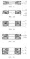
- Embodiment 7 of the invention is shown in FIG. 7.
- the damping body 2 consists of an inner and outer tubular rubber sleeve with high damping.
- the coil spring 1 is arranged in the hollow gap 7.
- the thrust resistance ring 4 is provided, which consists of the inner steel ring 4-1 and the outer elastic ring 4-2 made of plastic.
- the total height of the thrust resistance rings should be smaller than the smallest working height of the spring.
- the thrust resistance rings form a radial boundary for the spring, the damping force of the damping body being increased by this radial boundary arranged on the damping body, so that the damping effect of the damping body on the spring 1 is ensured.
- the spring can be made easier.
- the damping body may wear out after long-term use.
- the spring can also be vulcanized on the two rubber sleeves.
- Embodiment 8 of the invention is shown in FIG. 8.
- the outer surface of the spring wire of the coil spring 1 is coated here with a layer of a damping means 2, which is, for example, modified bitumen with a high attenuation.
- a damping means 2 which is, for example, modified bitumen with a high attenuation.
- a damping means 2 which is, for example, modified bitumen with a high attenuation.
- a damping means 2 which is, for example, modified bitumen with a high attenuation.
- a stiffer or a hard shear resistance layer can be applied to the damping body.
- Such an embodiment is suitable for springs with low damping or springs for large deformations.
- Embodiment 9 of the invention is shown in FIG. 9.
- the spring is a plate spring 5, which consists of several individual springs and is completely surrounded by the hollow cylindrical damping body 2.
- the damping body 2 is subjected to shear and compression. Because of the cavity in the center of the damper body 2, the damper body 2 can be easily deformed.
- Embodiment 10 of the invention is shown in FIG.
- the composite of several individual springs disc spring 5 is completely embedded in the hollow cylindrical damping body 2. Between the individual springs, there is an annular cavity 6. Therefore, the damping body is very easy to deform. The linearity of the stiffness characteristic and the damping are thereby significantly improved over the embodiment 9.
- a layer of elastic material is applied as a protective layer 8. This layer is advantageous in terms of the return of the damping material at discharge and protects the damping material against friction and shock from the outside.
- Embodiment 11 of the invention is shown in FIG. 11.
- the individual plate spring washers are embedded in the damping body 2, whose cross section is similar to the springs. There is no damping means in the contact area of the spring washers. As a result, permanent plastic deformation and destruction of the damping body during compression can be avoided.
- This design has little influence on the linearity of the stiffness characteristic and is suitable for cases where damping requirements are low but linearity requirements are high.
- the embodiment consists of individual spring washers and is suitable for mass production. To make the damping body in mass production, a damping material should be chosen which can be spray painted, dip coated, coated or cast, e.g. Polyurethane with strong cushioning.
- this embodiment is based on the embodiment 11, but wherein the damping body 2 is a hollow cylinder, which is easier to produce. On the upper and lower surfaces there are annular grooves. Thus, the damping body is relieved in the pressure range and avoided a strong non-linearity of the spring stiffness of the plate spring.
- Two plate spring washers 5 are stacked in the same direction (parallel stiffness) and embedded in the damping body.
- the damping body 2 is a hollow cylinder. Between the spring washers 5 is a damping means intended. Two spring complexes are placed on top of each other in series.
- Fig. 13 shows the structure.
- This embodiment is based on the embodiment 13.
- Two plate spring washers 5 are stacked in the same direction (parallel stiffness) and embedded in the same damping body 2.
- the cross section of the damping body 2 is similar to that of the spring leaves 5. Between the spring washers 5 damping material is provided. Two spring complexes are connected in series with each other.
- Embodiment 15 of the invention is shown in FIG.
- Two plate spring washers 5 are stacked in the opposite direction (series connection with higher rigidity) and embedded in the same damping body 2.
- the damping body 2 is a hollow cylinder. Between the spring washers 5 damping means is provided and there is a cavity 6 between the spring washers 5 and hollow grooves formed on the upper and lower sides. The two spring washers are placed in series.
- the different embodiments 11 to 15 have been explained because the mechanical properties of the plate spring are influenced by the arrangement of the plate spring washers.
- the spring stiffnesses are connected in parallel, so that the overall stiffness doubles. If the Belleville washers are stacked in opposite directions, the spring stiffnesses are connected in series, halving the overall stiffness. Based on these Property can be used in practice various combination of spring washers and spring bodies.
- damping materials are not compressible. If a lot of damping material is compressed in the pressure region of the damping body, the damping body is pushed perpendicular to the direction of force. As a result, the deformation characteristic of the spring is not linear and the damper body may be damaged because of severe deformation. This can be avoided if the damping body is made with cavities or of a soft elastic material or if a high-strength elastic outer layer is provided.
Landscapes
- Engineering & Computer Science (AREA)
- General Engineering & Computer Science (AREA)
- Mechanical Engineering (AREA)
- Springs (AREA)
- Vibration Dampers (AREA)
Applications Claiming Priority (2)
| Application Number | Priority Date | Filing Date | Title |
|---|---|---|---|
| CN 03112550 CN1263967C (zh) | 2003-06-11 | 2003-06-11 | 弹簧 |
| PCT/CN2004/000629 WO2004109147A1 (fr) | 2003-06-11 | 2004-06-11 | Ressort combine |
Publications (2)
| Publication Number | Publication Date |
|---|---|
| EP1643155A1 true EP1643155A1 (fr) | 2006-04-05 |
| EP1643155A4 EP1643155A4 (fr) | 2008-03-05 |
Family
ID=30122481
Family Applications (1)
| Application Number | Title | Priority Date | Filing Date |
|---|---|---|---|
| EP04738227A Withdrawn EP1643155A4 (fr) | 2003-06-11 | 2004-06-11 | Ressort combine |
Country Status (4)
| Country | Link |
|---|---|
| EP (1) | EP1643155A4 (fr) |
| JP (1) | JP2006527340A (fr) |
| CN (2) | CN100390436C (fr) |
| WO (1) | WO2004109147A1 (fr) |
Cited By (12)
| Publication number | Priority date | Publication date | Assignee | Title |
|---|---|---|---|---|
| DE102009019856A1 (de) * | 2009-05-06 | 2010-11-11 | Christian Bauer Gmbh & Co. Kg | Tellerfederanordnung |
| DE102013104926A1 (de) * | 2013-05-14 | 2014-11-20 | Grammer Ag | Fahrzeugschwingungsvorrichtung, Fahrzeugsitz und Fahrzeugkabine |
| EP2750906A4 (fr) * | 2011-08-31 | 2015-04-22 | Beijingwest Ind Co Ltd | Dispositif d'isolation des vibrations possédant une caractéristique force/déplacement non linaire et système de suspension de véhicule à moteur comprenant ce dispositif d'isolation des vibrations |
| US9371882B2 (en) | 2013-10-01 | 2016-06-21 | Grammer Ag | Shock absorber |
| US9377074B2 (en) | 2013-06-26 | 2016-06-28 | Grammer Ag | Device comprising a suspension system |
| US9802520B2 (en) | 2013-12-16 | 2017-10-31 | Grammer Ag | Vehicle seat having a horizontally movable seating surface for receiving a person |
| US9849816B2 (en) | 2013-06-04 | 2017-12-26 | Grammer Ag | Vehicle seat and motor vehicle or utility motor vehicle |
| US9879744B2 (en) | 2013-10-01 | 2018-01-30 | Grammer Ag | Vehicle with force-controlled shock absorber with regulating valve |
| US9937832B2 (en) | 2013-10-01 | 2018-04-10 | Grammer Ag | Vehicle seat or vehicle cabin having a suspension apparatus and utility vehicle |
| US9994239B2 (en) | 2013-10-01 | 2018-06-12 | Grammer Ag | Vehicle with force-controlled shock absorber (2-pipe shock absorber) |
| DE102010016388B4 (de) | 2009-04-10 | 2019-12-24 | Denso Corporation | Anlasser mit geräuschverringerndem Aufbau |
| WO2021110850A1 (fr) * | 2019-12-03 | 2021-06-10 | Basf Polyurethanes Gmbh | Butée anti-choc d'un système de suspension de véhicule automobile et procédé de fabrication d'une telle butée anti-choc |
Families Citing this family (18)
| Publication number | Priority date | Publication date | Assignee | Title |
|---|---|---|---|---|
| CN100390436C (zh) * | 2003-06-11 | 2008-05-28 | 尹学军 | 碟簧 |
| JP4716222B2 (ja) * | 2006-03-02 | 2011-07-06 | 株式会社ナベヤ | 除振マウント |
| CN101190707B (zh) * | 2006-12-01 | 2010-08-25 | 尹学军 | 船体表面缓冲减振装置 |
| CN102233464A (zh) * | 2010-04-27 | 2011-11-09 | 王丕文 | 线切割机绕线系统的减振机构 |
| CN102976201A (zh) * | 2011-09-07 | 2013-03-20 | 北京南口轨道交通机械有限责任公司 | 吊具 |
| CN102734367B (zh) * | 2012-05-11 | 2015-06-10 | 青岛科而泰环境控制技术有限公司 | 一种摩擦式阻尼器 |
| JP5923397B2 (ja) * | 2012-06-29 | 2016-05-24 | 株式会社ショーワ | シートダンパー |
| JP6341830B2 (ja) * | 2014-10-14 | 2018-06-13 | 株式会社東海理化電機製作所 | 車両用視認装置 |
| CN106555832A (zh) * | 2016-12-08 | 2017-04-05 | 河南师范大学 | 摩擦金属螺旋弹簧式阻尼器 |
| CN108790666A (zh) * | 2017-07-06 | 2018-11-13 | 吴振彪 | 一种电动车辆悬架 |
| CN107630970B (zh) * | 2017-10-17 | 2024-02-20 | 株洲时代新材料科技股份有限公司 | 用于齿轮箱液压支撑装置的液体复合弹簧 |
| CN108035728B (zh) * | 2017-11-22 | 2019-07-23 | 天津大学 | 模拟tbm施工作业真实工况实验台的围岩特性模拟装置 |
| US11458791B2 (en) | 2018-03-08 | 2022-10-04 | Volvo Truck Corporation | Spring assembly for a vehicle bogie suspension arrangement |
| CN109026604A (zh) * | 2018-08-20 | 2018-12-18 | 珠海格力电器股份有限公司 | 一种减振装置、压缩机及空调 |
| CN110549647B (zh) * | 2019-09-09 | 2022-02-25 | 东北林业大学 | 一种碟形碳纤维复合材料组合压簧结构及其制造方法 |
| CN112382878B (zh) * | 2020-11-04 | 2022-06-28 | 贵州航天电器股份有限公司 | 一种具有复合镀层的插孔合件、电连接器及其电镀方法 |
| CN115929841A (zh) * | 2021-09-24 | 2023-04-07 | 中国石油化工股份有限公司 | 一种防撞减振保护装置 |
| CN114922934B (zh) * | 2022-06-06 | 2024-05-31 | 张然 | 一种压敏胶缓冲减震器 |
Family Cites Families (20)
| Publication number | Priority date | Publication date | Assignee | Title |
|---|---|---|---|---|
| FR952861A (fr) * | 1946-11-29 | 1949-11-25 | Ford | Dispositif de montage des moteurs |
| US2605099A (en) * | 1949-01-07 | 1952-07-29 | Firestone Tire & Rubber Co | Rubber-metal spring |
| US3279779A (en) * | 1964-07-20 | 1966-10-18 | Lord Corp | Combined disc and elastomeric spring |
| US3416783A (en) * | 1965-11-19 | 1968-12-17 | Firgat S N C | Rubber-metal spring device |
| GB1378352A (en) * | 1972-02-22 | 1974-12-27 | Mini Verkehrswesen | Support for an automatic central buffer coupling arm of a rail vehicle |
| JPS5554631U (fr) * | 1978-10-03 | 1980-04-12 | ||
| JPS6026342U (ja) * | 1983-07-29 | 1985-02-22 | 三菱自動車工業株式会社 | 非線形コイルばね |
| JPS61144439A (ja) * | 1984-12-12 | 1986-07-02 | ザ パットン コーポレイション | 合成スプリング |
| DE3637294A1 (de) * | 1986-11-03 | 1988-05-11 | Wolf Woco & Co Franz J | Tragfedersystem |
| CN2051316U (zh) * | 1989-02-24 | 1990-01-17 | 吴万才 | 螺旋橡胶复合弹簧 |
| JPH06337077A (ja) * | 1993-05-27 | 1994-12-06 | Nanomaizaa Kk | 安全弁 |
| CN2213255Y (zh) * | 1994-06-07 | 1995-11-22 | 南通港务局狼山港务公司 | 碟簧阻尼橡胶缓冲器 |
| JPH09264079A (ja) * | 1996-03-29 | 1997-10-07 | Kazuo Yuzuhara | 木造建築物における免震装置 |
| CN2263232Y (zh) * | 1996-10-18 | 1997-09-24 | 吴利群 | 组合式可变碟簧支吊架 |
| JPH11141605A (ja) * | 1997-11-04 | 1999-05-25 | Nec Corp | サスペンション構造 |
| SE513766C2 (sv) * | 1998-03-13 | 2000-10-30 | Alfa Laval Ab | Stödanordning för en king en rotationsaxel roterbar spindel som uppbär en centrifugrotor |
| CN1277331A (zh) * | 1998-04-30 | 2000-12-20 | 贾喜亭 | 一种车辆悬架弹性元件 |
| JP2000120742A (ja) * | 1998-10-08 | 2000-04-25 | Tokkyo Kiki Kk | 制振部材とその製造方法 |
| CN2644775Y (zh) * | 2003-06-11 | 2004-09-29 | 尹学军 | 弹簧 |
| CN100390436C (zh) * | 2003-06-11 | 2008-05-28 | 尹学军 | 碟簧 |
-
2003
- 2003-06-11 CN CNB2005101196034A patent/CN100390436C/zh not_active Expired - Fee Related
- 2003-06-11 CN CN 03112550 patent/CN1263967C/zh not_active Expired - Fee Related
-
2004
- 2004-06-11 JP JP2006515631A patent/JP2006527340A/ja active Pending
- 2004-06-11 EP EP04738227A patent/EP1643155A4/fr not_active Withdrawn
- 2004-06-11 WO PCT/CN2004/000629 patent/WO2004109147A1/fr not_active Ceased
Cited By (14)
| Publication number | Priority date | Publication date | Assignee | Title |
|---|---|---|---|---|
| DE102010016388B4 (de) | 2009-04-10 | 2019-12-24 | Denso Corporation | Anlasser mit geräuschverringerndem Aufbau |
| DE102009019856A1 (de) * | 2009-05-06 | 2010-11-11 | Christian Bauer Gmbh & Co. Kg | Tellerfederanordnung |
| US9517671B2 (en) | 2011-08-31 | 2016-12-13 | Beijing West Industries Co, Ltd. | Vibroisolating device with a nonlinear force vs. displacement characteristic and a motor vehicle suspension system comprising such vibroisolating device |
| EP2750906A4 (fr) * | 2011-08-31 | 2015-04-22 | Beijingwest Ind Co Ltd | Dispositif d'isolation des vibrations possédant une caractéristique force/déplacement non linaire et système de suspension de véhicule à moteur comprenant ce dispositif d'isolation des vibrations |
| US9140328B2 (en) | 2013-05-14 | 2015-09-22 | Grammer Ag | Vehicle vibration device, vehicle seat and vehicle cab |
| DE102013104926A1 (de) * | 2013-05-14 | 2014-11-20 | Grammer Ag | Fahrzeugschwingungsvorrichtung, Fahrzeugsitz und Fahrzeugkabine |
| US9849816B2 (en) | 2013-06-04 | 2017-12-26 | Grammer Ag | Vehicle seat and motor vehicle or utility motor vehicle |
| US9377074B2 (en) | 2013-06-26 | 2016-06-28 | Grammer Ag | Device comprising a suspension system |
| US9371882B2 (en) | 2013-10-01 | 2016-06-21 | Grammer Ag | Shock absorber |
| US9879744B2 (en) | 2013-10-01 | 2018-01-30 | Grammer Ag | Vehicle with force-controlled shock absorber with regulating valve |
| US9937832B2 (en) | 2013-10-01 | 2018-04-10 | Grammer Ag | Vehicle seat or vehicle cabin having a suspension apparatus and utility vehicle |
| US9994239B2 (en) | 2013-10-01 | 2018-06-12 | Grammer Ag | Vehicle with force-controlled shock absorber (2-pipe shock absorber) |
| US9802520B2 (en) | 2013-12-16 | 2017-10-31 | Grammer Ag | Vehicle seat having a horizontally movable seating surface for receiving a person |
| WO2021110850A1 (fr) * | 2019-12-03 | 2021-06-10 | Basf Polyurethanes Gmbh | Butée anti-choc d'un système de suspension de véhicule automobile et procédé de fabrication d'une telle butée anti-choc |
Also Published As
| Publication number | Publication date |
|---|---|
| CN100390436C (zh) | 2008-05-28 |
| CN1470779A (zh) | 2004-01-28 |
| JP2006527340A (ja) | 2006-11-30 |
| EP1643155A4 (fr) | 2008-03-05 |
| CN1776247A (zh) | 2006-05-24 |
| CN1263967C (zh) | 2006-07-12 |
| WO2004109147A1 (fr) | 2004-12-16 |
Similar Documents
| Publication | Publication Date | Title |
|---|---|---|
| EP1643155A1 (fr) | Ressort combine | |
| EP1995088B1 (fr) | Elément de palier d'insertion, élément de palier d'insertion élastique et dispositif de support de jambe de suspension à ressort | |
| DE3509923A1 (de) | Federelement | |
| DE3431460A1 (de) | Fluidgefuellte federnde buchsenkonstruktion | |
| EP2031272A2 (fr) | Amortisseur de vibrations de torsions | |
| DE102008050202A1 (de) | Elastischer Gelenkkörper | |
| DE19626754A1 (de) | Federelement mit gestricktem Formkörper | |
| DE69714716T2 (de) | Lageraufbau mit rillendaube | |
| DE102018102758A1 (de) | Feder für ein Rückschlagventil, Rückschlagventil mit einer derartigen Feder, regelbarer Schwingungsdämpfer mit einem solchen Rückschlagventil sowie Kraftfahrzeug mit einem derartigen regelbaren Schwingungsdämpfer | |
| EP2784220B1 (fr) | Appui à pot | |
| DE3833182C2 (fr) | ||
| EP3612746B1 (fr) | Unité à coin d'écartement | |
| DE2933586C2 (de) | Schwingungstilger für rotierende Wellen | |
| DE102012009222A1 (de) | Schwingungsdämpfer für ein Fahrzeug | |
| DE2721399A1 (de) | Feder | |
| DE102018101656A1 (de) | Radialwellen-Dichtungsvorrichtung | |
| EP1342019B9 (fr) | Element de ressort en un materiau elastique, en particulier en matiere plastique | |
| EP0985838B1 (fr) | Palier et méthode pour sa fabrication | |
| DE1959298A1 (de) | Schichtfeder aus mehreren hintereinandergeschalteten,druckbeanspruchten Gummi-Metall-Federscheiben | |
| EP1231406A2 (fr) | Dispositif d'amortissement de vibration | |
| EP3267143B1 (fr) | Projectile | |
| DE3033940C2 (de) | Elastische Wellenkupplung | |
| DE19714749C2 (de) | Druckfedereinrichtung | |
| DE19854692A1 (de) | Federelement aus Faserverbundwerkstoff mit eingelagerten weichen Schichten | |
| DE4324000A1 (de) | Elastisches Gleitlager |
Legal Events
| Date | Code | Title | Description |
|---|---|---|---|
| PUAI | Public reference made under article 153(3) epc to a published international application that has entered the european phase |
Free format text: ORIGINAL CODE: 0009012 |
|
| 17P | Request for examination filed |
Effective date: 20060111 |
|
| AK | Designated contracting states |
Kind code of ref document: A1 Designated state(s): AT BE BG CH CY CZ DE DK EE ES FI FR GB GR HU IE IT LI LU MC NL PL PT RO SE SI SK TR |
|
| DAX | Request for extension of the european patent (deleted) | ||
| A4 | Supplementary search report drawn up and despatched |
Effective date: 20080206 |
|
| 17Q | First examination report despatched |
Effective date: 20080701 |
|
| RAP1 | Party data changed (applicant data changed or rights of an application transferred) |
Owner name: GERB SCHWINGUNGSISOLIERUNGEN GMBH & CO. KG Owner name: YIN, XUEJUN |
|
| RIN1 | Information on inventor provided before grant (corrected) |
Inventor name: YIN, XUEJUN |
|
| RAP1 | Party data changed (applicant data changed or rights of an application transferred) |
Owner name: GERB SCHWINGUNGSISOLIERUNGEN GMBH & CO. KG Owner name: YIN, XUEJUN |
|
| RIN1 | Information on inventor provided before grant (corrected) |
Inventor name: YIN, XUEJUN7 JIN GANG SHAN ROAD |
|
| STAA | Information on the status of an ep patent application or granted ep patent |
Free format text: STATUS: THE APPLICATION IS DEEMED TO BE WITHDRAWN |
|
| 18D | Application deemed to be withdrawn |
Effective date: 20100429 |