EP1650426A2 - Nutzfahrzeug - Google Patents
Nutzfahrzeug Download PDFInfo
- Publication number
- EP1650426A2 EP1650426A2 EP05109561A EP05109561A EP1650426A2 EP 1650426 A2 EP1650426 A2 EP 1650426A2 EP 05109561 A EP05109561 A EP 05109561A EP 05109561 A EP05109561 A EP 05109561A EP 1650426 A2 EP1650426 A2 EP 1650426A2
- Authority
- EP
- European Patent Office
- Prior art keywords
- air
- fan shroud
- outlet
- air passage
- intake
- Prior art date
- Legal status (The legal status is an assumption and is not a legal conclusion. Google has not performed a legal analysis and makes no representation as to the accuracy of the status listed.)
- Granted
Links
- 238000002485 combustion reaction Methods 0.000 claims abstract description 17
- 238000001816 cooling Methods 0.000 description 6
- 239000000446 fuel Substances 0.000 description 4
- 238000004806 packaging method and process Methods 0.000 description 4
- 239000000463 material Substances 0.000 description 3
- XLYOFNOQVPJJNP-UHFFFAOYSA-N water Substances O XLYOFNOQVPJJNP-UHFFFAOYSA-N 0.000 description 3
- POIUWJQBRNEFGX-XAMSXPGMSA-N cathelicidin Chemical compound C([C@@H](C(=O)N[C@@H](CCCNC(N)=N)C(=O)N[C@@H](CCCCN)C(=O)N[C@@H](CO)C(=O)N[C@@H](CCCCN)C(=O)N[C@@H](CCC(O)=O)C(=O)N[C@@H](CCCCN)C(=O)N[C@@H]([C@@H](C)CC)C(=O)NCC(=O)N[C@@H](CCCCN)C(=O)N[C@@H](CCC(O)=O)C(=O)N[C@@H](CC=1C=CC=CC=1)C(=O)N[C@@H](CCCCN)C(=O)N[C@@H](CCCNC(N)=N)C(=O)N[C@@H]([C@@H](C)CC)C(=O)N[C@@H](C(C)C)C(=O)N[C@@H](CCC(N)=O)C(=O)N[C@@H](CCCNC(N)=N)C(=O)N[C@@H]([C@@H](C)CC)C(=O)N[C@@H](CCCCN)C(=O)N[C@@H](CC(O)=O)C(=O)N[C@@H](CC=1C=CC=CC=1)C(=O)N[C@@H](CC(C)C)C(=O)N[C@@H](CCCNC(N)=N)C(=O)N[C@@H](CC(N)=O)C(=O)N[C@@H](CC(C)C)C(=O)N[C@@H](C(C)C)C(=O)N1[C@@H](CCC1)C(=O)N[C@@H](CCCNC(N)=N)C(=O)N[C@@H]([C@@H](C)O)C(=O)N[C@@H](CCC(O)=O)C(=O)N[C@@H](CO)C(O)=O)NC(=O)[C@H](CC=1C=CC=CC=1)NC(=O)[C@H](CC(O)=O)NC(=O)CNC(=O)[C@H](CC(C)C)NC(=O)[C@@H](N)CC(C)C)C1=CC=CC=C1 POIUWJQBRNEFGX-XAMSXPGMSA-N 0.000 description 2
- 238000004140 cleaning Methods 0.000 description 2
- 238000001914 filtration Methods 0.000 description 2
- 238000009428 plumbing Methods 0.000 description 2
- 238000011144 upstream manufacturing Methods 0.000 description 2
- 229910000906 Bronze Inorganic materials 0.000 description 1
- RYGMFSIKBFXOCR-UHFFFAOYSA-N Copper Chemical compound [Cu] RYGMFSIKBFXOCR-UHFFFAOYSA-N 0.000 description 1
- 239000004743 Polypropylene Substances 0.000 description 1
- 238000004378 air conditioning Methods 0.000 description 1
- 229910052782 aluminium Inorganic materials 0.000 description 1
- XAGFODPZIPBFFR-UHFFFAOYSA-N aluminium Chemical compound [Al] XAGFODPZIPBFFR-UHFFFAOYSA-N 0.000 description 1
- 239000010974 bronze Substances 0.000 description 1
- 239000002826 coolant Substances 0.000 description 1
- 229910052802 copper Inorganic materials 0.000 description 1
- 239000010949 copper Substances 0.000 description 1
- KUNSUQLRTQLHQQ-UHFFFAOYSA-N copper tin Chemical compound [Cu].[Sn] KUNSUQLRTQLHQQ-UHFFFAOYSA-N 0.000 description 1
- 230000000694 effects Effects 0.000 description 1
- 239000002828 fuel tank Substances 0.000 description 1
- 239000003365 glass fiber Substances 0.000 description 1
- 229910052500 inorganic mineral Inorganic materials 0.000 description 1
- 238000003780 insertion Methods 0.000 description 1
- 230000037431 insertion Effects 0.000 description 1
- 229910052751 metal Inorganic materials 0.000 description 1
- 239000002184 metal Substances 0.000 description 1
- 238000000034 method Methods 0.000 description 1
- 239000011707 mineral Substances 0.000 description 1
- 238000012986 modification Methods 0.000 description 1
- 230000004048 modification Effects 0.000 description 1
- -1 polypropylene Polymers 0.000 description 1
- 229920001155 polypropylene Polymers 0.000 description 1
- 238000005406 washing Methods 0.000 description 1
Images
Classifications
-
- F—MECHANICAL ENGINEERING; LIGHTING; HEATING; WEAPONS; BLASTING
- F02—COMBUSTION ENGINES; HOT-GAS OR COMBUSTION-PRODUCT ENGINE PLANTS
- F02M—SUPPLYING COMBUSTION ENGINES IN GENERAL WITH COMBUSTIBLE MIXTURES OR CONSTITUENTS THEREOF
- F02M35/00—Combustion-air cleaners, air intakes, intake silencers, or induction systems specially adapted for, or arranged on, internal-combustion engines
- F02M35/02—Air cleaners
- F02M35/024—Air cleaners using filters, e.g. moistened
-
- F—MECHANICAL ENGINEERING; LIGHTING; HEATING; WEAPONS; BLASTING
- F02—COMBUSTION ENGINES; HOT-GAS OR COMBUSTION-PRODUCT ENGINE PLANTS
- F02M—SUPPLYING COMBUSTION ENGINES IN GENERAL WITH COMBUSTIBLE MIXTURES OR CONSTITUENTS THEREOF
- F02M35/00—Combustion-air cleaners, air intakes, intake silencers, or induction systems specially adapted for, or arranged on, internal-combustion engines
- F02M35/02—Air cleaners
- F02M35/04—Air cleaners specially arranged with respect to engine, to intake system or specially adapted to vehicle; Mounting thereon ; Combinations with other devices
- F02M35/06—Air cleaners specially arranged with respect to engine, to intake system or specially adapted to vehicle; Mounting thereon ; Combinations with other devices combined or associated with engine's cooling blower or fan, or with flywheel
-
- F—MECHANICAL ENGINEERING; LIGHTING; HEATING; WEAPONS; BLASTING
- F01—MACHINES OR ENGINES IN GENERAL; ENGINE PLANTS IN GENERAL; STEAM ENGINES
- F01P—COOLING OF MACHINES OR ENGINES IN GENERAL; COOLING OF INTERNAL-COMBUSTION ENGINES
- F01P11/00—Component parts, details, or accessories not provided for in, or of interest apart from, groups F01P1/00 - F01P9/00
- F01P11/10—Guiding or ducting cooling-air, to, or from, liquid-to-air heat exchangers
-
- F—MECHANICAL ENGINEERING; LIGHTING; HEATING; WEAPONS; BLASTING
- F02—COMBUSTION ENGINES; HOT-GAS OR COMBUSTION-PRODUCT ENGINE PLANTS
- F02M—SUPPLYING COMBUSTION ENGINES IN GENERAL WITH COMBUSTIBLE MIXTURES OR CONSTITUENTS THEREOF
- F02M35/00—Combustion-air cleaners, air intakes, intake silencers, or induction systems specially adapted for, or arranged on, internal-combustion engines
- F02M35/16—Combustion-air cleaners, air intakes, intake silencers, or induction systems specially adapted for, or arranged on, internal-combustion engines characterised by use in vehicles
- F02M35/162—Motorcycles; All-terrain vehicles, e.g. quads, snowmobiles; Small vehicles, e.g. forklifts
Definitions
- This invention relates generally to a utility vehicle, preferably a tractor, having a longitudinal axis, an internal combustion engine, a radiator positioned in a generally vertical alignment adjacent the internal combustion engine, and a fan shroud positioned between the radiator and the internal combustion engine; an air passage extending through the fan shroud and an air filter.
- Packaging space for under-hood components of compact tractors is very limited.
- Packaged components include the air intake system, exhaust system, fuel supply system, engine cooling system, HVAC system, and electrical system. It is desirable to provide easy access to frequently serviced items in the engine compartment such as the engine air filter, fuel filter, oil level fill and check, coolant water level check, etc. It also would be desirable to perform frequent service activities without special tools, and without having to remove components that are not being serviced.
- Performance of the air intake system affects the power output of an internal combustion engine. For example, power output may be reduced if the air intake system allows entry of heat and/or moisture into the inlet air during its path through the intake system inside of the engine compartment. Additionally, power output may be reduced if the air intake system permits a pressure drop of the air flow traveling through the intake system. Air intake systems typically have several components and connections that potentially allow entry of heat or moisture, or pressure drops due to air leaks.
- US-A-5,277,157 shows a mounting arrangement provided for mounting the air cleaner for an internal combustion engine in a vehicle.
- the air cleaner generally includes a casing having air inlet and outlet openings and an open side, a pot-shaped housing containing a filter element and having an open side selectively attachable to the open side of the casing.
- the mounting arrangement provides two substantially parallel and horizontal rods upon which the air cleaner can be placed. The air cleaner can be held to the rods by a variety of techniques, including hooks and guide rings.
- the integrated fan shroud air intake system provides an air passage through the cooling system fan shroud of a compact tractor upstream of the air filter.
- the air filter is mounted directly to the fan shroud in an alignment transverse to the longitudinal axis of the vehicle.
- the air filter inlet is plugged directly into the fan shroud.
- the integrated fan shroud air intake system reduces air filter mounting costs, improves serviceability of the air filter, reduces intake plumbing, reduces heat added to the inlet air, and improves packaging efficiency of the air filter.
- the integrated fan shroud air intake system may be used in a small or compact tractor, but also may be used in other work vehicles such as off-road or mowing vehicles.
- the integrated fan shroud air intake system receives and filters a sufficient volume of air for fuel combustion in an internal combustion engine.
- the integrated fan shroud air intake system requires less space under the hood than previous systems, helps improve power output of the internal combustion engine by minimizing the entry of heat and/or moisture into the intake air, and has fewer components, connectors, and potential leak paths than previous air intake systems. Additionally, the integrated fan shroud air intake system is less costly to assemble and service.
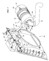
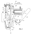
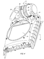
- the integrated fan shroud air intake system provides an air passage through the cooling system fan shroud 19 of a compact tractor.
- Air filter 11 is mounted directly to the fan shroud in an alignment transverse to the longitudinal axis of the vehicle.
- radiator 10 and fan shroud 19 are positioned in front of and adjacent to an internal combustion engine under a tractor hood.
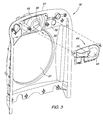
- the fan shroud has a first face 32 that may be attached or fastened to the radiator, and a second face 33 that faces the engine.
- the fan shroud may have a generally cylindrical or circular central opening 31 that may surround a cooling fan (not shown) that rotates on a generally longitudinal axis.
- the fan may be driven by an internal combustion engine, or may be electrically or hydraulically powered, and may have a plurality of blades which rotate to cause air to move through a radiator.
- the radiator and fan shroud may have a generally vertical alignment, or may be at an angle of less than about 30 degrees from vertical.
- at least part of the radiator may be aluminum, copper or bronze material, with a releasable radiator cap 18.
- the fan shroud may be molded or formed from a polymeric material such as glass fiber mineral reinforced, highly chemically coupled polypropylene.
- the fan shroud may have a nominal material wall thickness of between about 2 mm and about 10 mm, and most preferably about 3.5 mm. Alternatively, the fan shroud may be formed of sheet metal.
- air filter 11 may be mounted to second face 33 of the fan shroud at or near the uppermost edge 51 of the fan shroud. When mounted to the fan shroud, the air filter may be aligned so that the axis of cylindrical housing 39 is transverse to the longitudinal axis of the vehicle.
- releasable securing hardware such as strap 14 and bracket 26, may extend at least partially around the cylindrical housing of the air filter and help secure the housing to the fan shroud. The securing hardware allows the air filter to be easily removed and reattached manually for replacement, servicing or cleaning.
- passage 30 extends through fan shroud 19 upstream of the air filter. Passage 30 may be positioned at or near the uppermost edge 51 of the fan shroud. At least part of passage 30 may be transverse to the longitudinal axis of the vehicle, providing for a lateral air flow path. Passage 30 extends through the fan shroud and/or may project from one or both faces of the fan shroud. Passage 30 may have a small orifice at the lower surface thereof for removal of entrapped water from the system. In one embodiment, passage 30 may include a plenum having an internal volume of between about 0.01 cubic meters and about 0.1 cubic meters.
- the passage and/or plenum may have an air intake and an outlet.
- Intake 34 may project from the first face of the fan shroud at or near the uppermost edge of the fan shroud.
- Outlet 35 may project from the second face of the fan shroud at or near the uppermost edge.
- Intake 34 may be laterally spaced from outlet 35.
- intake 34 may be spaced laterally between about 1 cm and about 20 cm from outlet 35.
- At least one of the intake 34 and outlet 35 may be integral with and molded together with the fan shroud.
- the intake 34 and outlet 35 each may project between about 1 cm and about 10 cm from the respective faces of the fan shroud.
- Intake 34 may have a generally oblong flange in cross section, and outlet 35 may have a generally cylindrical flange.
- the passage may include a plenum between cover 44 and fan shroud panel 45.
- a plenum may be provided by attaching cover 44 to fan shroud panel 45 with threaded fasteners.
- Intake 34 may extend through cover 44, and outlet 35 may extend through panel 45.
- Cover 44 also may have an outwardly facing cavity 49 to provide adequate room for manual access to radiator cap 18. Cover 44 should prevent water entering the passage or plenum either from the engine cooling system or from pressure washing of the vehicle cooling system. Cover 44 may be removable to allow cleaning of any debris trapped within the plenum.
- one or more air filter mounting ribs 20, 27 may project from the second face of the fan shroud and/or plenum.
- Mounting ribs 20, 27 may be shaped or contoured to match and correspond to the housing or outer surface of air filter 11, helping to position and secure the air filter to the fan shroud.
- mounting ribs 20, 27 may have arced surfaces to match the cylindrical housing 39 of air filter 11.
- cylindrical housing 39 may have a first end 41 and a second end 42, and cover 29 releasably attached to the second end.
- Dirty air inlet 21 may be adjacent the first end 41. Dirty air may enter the air filter through inlet 21 and be filtered with filtration elements before exiting through clean air outlet 24.
- inlet 21 may be transverse to and extend outwardly from the cylindrical body of the housing. Dirty air inlet 21 may plug directly into outlet 35 extending from the second face of the fan shroud, and may have a snug fit to allow manual insertion or removal from outlet 35 without tools.
- inlet 21 may have an external diameter the same or not more than about 5 mm less than the internal diameter of outlet 35.
- clean air outlet 24 may extend axially from first end 41 of the air filter housing. Valve 16 in the clean air outlet may be operable to control and/or restrict the air flow. Outlet 24 may be secured to hose 25 with a conventional clamping device, which routes clean filtered air to one or more fuel delivery components of the internal combustion engine.
- the integrated fan shroud air intake system may be serviced by raising the vehicle engine compartment cover, removing the air filter housing cover and then removing the filtration elements.
- Advantages of the system may include reduced air filter mounting costs, improved serviceability of the air filter, reduced intake plumbing, reduced heat added to the inlet air, and improved packaging efficiency of the air filter.
- the improved packaging efficiency may allow additional space for other engine compartment components such as air conditioning, fuel tank, etc.
Landscapes
- Engineering & Computer Science (AREA)
- Chemical & Material Sciences (AREA)
- Combustion & Propulsion (AREA)
- Mechanical Engineering (AREA)
- General Engineering & Computer Science (AREA)
- Cooling, Air Intake And Gas Exhaust, And Fuel Tank Arrangements In Propulsion Units (AREA)
Applications Claiming Priority (1)
| Application Number | Priority Date | Filing Date | Title |
|---|---|---|---|
| US10/972,937 US7278504B2 (en) | 2004-10-25 | 2004-10-25 | Integrated fan shroud air intake system |
Publications (3)
| Publication Number | Publication Date |
|---|---|
| EP1650426A2 true EP1650426A2 (de) | 2006-04-26 |
| EP1650426A3 EP1650426A3 (de) | 2012-02-22 |
| EP1650426B1 EP1650426B1 (de) | 2013-06-26 |
Family
ID=35708792
Family Applications (1)
| Application Number | Title | Priority Date | Filing Date |
|---|---|---|---|
| EP05109561.0A Expired - Lifetime EP1650426B1 (de) | 2004-10-25 | 2005-10-14 | Nutzfahrzeug |
Country Status (2)
| Country | Link |
|---|---|
| US (1) | US7278504B2 (de) |
| EP (1) | EP1650426B1 (de) |
Cited By (3)
| Publication number | Priority date | Publication date | Assignee | Title |
|---|---|---|---|---|
| DE102013007157A1 (de) * | 2013-04-24 | 2014-10-30 | GM Global Technology Operations, LLC (n.d. Ges. d. Staates Delaware) | Luftführungsvorrichtung |
| WO2016009121A1 (fr) * | 2014-07-15 | 2016-01-21 | Peugeot Citroen Automobiles Sa | Groupe moto-ventilateur incorporant une buse et un écran thermique |
| CN106917705A (zh) * | 2017-05-12 | 2017-07-04 | 广西玉柴机器股份有限公司 | 一种支撑空气滤清器的装置 |
Families Citing this family (13)
| Publication number | Priority date | Publication date | Assignee | Title |
|---|---|---|---|---|
| US7350609B2 (en) * | 2004-06-16 | 2008-04-01 | Daikyonishikawa Corporation | Vehicle front end structure |
| US8807113B2 (en) * | 2009-05-04 | 2014-08-19 | Ford Global Technologies, Llc | Device and method for integrating an air cleaner into a radiator fan shroud |
| US20100301638A1 (en) * | 2009-05-29 | 2010-12-02 | Hinshaw Eric J | Integrated Air Intake System |
| US8256551B2 (en) * | 2009-12-30 | 2012-09-04 | Agco Corporation | Agricultural vehicle cooling assembly fan shroud with seals for pass-through cooling and exhaust tubes |
| JP5033226B2 (ja) * | 2010-08-02 | 2012-09-26 | 株式会社小松製作所 | 作業車両 |
| US8783400B2 (en) * | 2012-06-06 | 2014-07-22 | Honda Motor Co., Ltd. | Fan cover structure for a radiator assembly |
| EP2733342B1 (de) | 2012-11-15 | 2015-08-19 | CNH Industrial Italia S.p.A. | Luftfilteranordnung für ein Arbeitsfahrzeug |
| US9222448B2 (en) | 2014-02-14 | 2015-12-29 | Cnh Industrial America Llc | Air intake system for a work vehicle with improved fan aspiration |
| JP2017178246A (ja) * | 2016-03-31 | 2017-10-05 | ヤンマー株式会社 | 作業車両 |
| DE102019213195A1 (de) * | 2019-09-02 | 2021-03-04 | Deere & Company | Lüfterhutze für ein Fahrzeugsystem |
| USD971965S1 (en) * | 2020-06-26 | 2022-12-06 | Powerhouse Engine Solutions Switzerland IP Holding GmbH | Intake manifold section |
| USD941363S1 (en) * | 2020-06-26 | 2022-01-18 | Powerhouse Engine Solutions Switzerland IP Holding GmbH | Intake manifold section |
| USD1065253S1 (en) * | 2021-03-17 | 2025-03-04 | No Limit Enterprises, Inc. | Open air intake |
Citations (2)
| Publication number | Priority date | Publication date | Assignee | Title |
|---|---|---|---|---|
| US5277157A (en) | 1992-02-11 | 1994-01-11 | Deere & Company | Mounting arrangement for an air cleaner |
| US20020023731A1 (en) | 2000-08-30 | 2002-02-28 | Kawasaki Jukogyo Kabushiki Kaisha | Radiator unit for engine and method of combining the same with engine |
Family Cites Families (15)
| Publication number | Priority date | Publication date | Assignee | Title |
|---|---|---|---|---|
| US2197503A (en) * | 1938-04-30 | 1940-04-16 | Oliver Farm Equipment Co | Air intake for air cleaners |
| US2708920A (en) * | 1954-02-24 | 1955-05-24 | Deere & Co | Air intake pre-cleaner |
| DE3232583A1 (de) * | 1982-09-02 | 1984-03-08 | Daimler-Benz Ag, 7000 Stuttgart | Vorrichtung zur reinigung der ansaugluft einer brennkraftmaschine |
| US5427502A (en) | 1994-03-28 | 1995-06-27 | Deere & Company | Fan shroud aspirator |
| US5564513A (en) * | 1994-07-12 | 1996-10-15 | Automotive Performance International, Inc. | Air filter housing for automobile internal combustion engine |
| JP3591565B2 (ja) * | 1997-04-17 | 2004-11-24 | スズキ株式会社 | 内燃機関の吸気装置 |
| JPH10329754A (ja) * | 1997-05-29 | 1998-12-15 | Aisin Seiki Co Ltd | 車両フロントエンドモジュール構造 |
| JP4096389B2 (ja) * | 1997-12-10 | 2008-06-04 | マツダ株式会社 | 自動車の前部構造 |
| MXPA01003866A (es) * | 1998-10-22 | 2002-05-06 | Mccord Winn Textron Inc | Guardera de ventilador y arreglo de admision de aire. |
| US6648089B1 (en) * | 2000-08-07 | 2003-11-18 | International Truck Intellectual Property Company, Llc | Cooling module mounting system and assembly process |
| US6732784B2 (en) * | 2000-09-06 | 2004-05-11 | Jacques Dion | Cooling system module and structure for mounting same in a vehicle |
| DE10202533A1 (de) * | 2002-01-24 | 2003-08-14 | Porsche Ag | Einrichtung zum Abführen von Wasser, Staub und dergleichen |
| US6698539B2 (en) * | 2002-04-09 | 2004-03-02 | Almarv, Llc | Intake apparatus for feeding air to engine compartment |
| US6907854B2 (en) * | 2003-09-30 | 2005-06-21 | Deere & Company | Fan shroud with internal aspirator |
| US6976825B2 (en) * | 2003-09-30 | 2005-12-20 | Deere & Company | Integrated aspirator and fan shroud |
-
2004
- 2004-10-25 US US10/972,937 patent/US7278504B2/en not_active Expired - Lifetime
-
2005
- 2005-10-14 EP EP05109561.0A patent/EP1650426B1/de not_active Expired - Lifetime
Patent Citations (2)
| Publication number | Priority date | Publication date | Assignee | Title |
|---|---|---|---|---|
| US5277157A (en) | 1992-02-11 | 1994-01-11 | Deere & Company | Mounting arrangement for an air cleaner |
| US20020023731A1 (en) | 2000-08-30 | 2002-02-28 | Kawasaki Jukogyo Kabushiki Kaisha | Radiator unit for engine and method of combining the same with engine |
Cited By (7)
| Publication number | Priority date | Publication date | Assignee | Title |
|---|---|---|---|---|
| DE102013007157A1 (de) * | 2013-04-24 | 2014-10-30 | GM Global Technology Operations, LLC (n.d. Ges. d. Staates Delaware) | Luftführungsvorrichtung |
| WO2016009121A1 (fr) * | 2014-07-15 | 2016-01-21 | Peugeot Citroen Automobiles Sa | Groupe moto-ventilateur incorporant une buse et un écran thermique |
| FR3023870A1 (fr) * | 2014-07-15 | 2016-01-22 | Peugeot Citroen Automobiles Sa | Groupe moto-ventilateur incorporant une buse et un ecran thermique |
| CN106660442A (zh) * | 2014-07-15 | 2017-05-10 | 标致雪铁龙集团 | 包括风道和隔热屏的机动风扇总成 |
| CN106660442B (zh) * | 2014-07-15 | 2020-03-31 | 标致雪铁龙集团 | 包括风道和隔热屏的机动风扇总成 |
| CN106917705A (zh) * | 2017-05-12 | 2017-07-04 | 广西玉柴机器股份有限公司 | 一种支撑空气滤清器的装置 |
| CN106917705B (zh) * | 2017-05-12 | 2018-06-29 | 广西玉柴机器股份有限公司 | 一种支撑空气滤清器的装置 |
Also Published As
| Publication number | Publication date |
|---|---|
| US7278504B2 (en) | 2007-10-09 |
| EP1650426A3 (de) | 2012-02-22 |
| US20060086549A1 (en) | 2006-04-27 |
| EP1650426B1 (de) | 2013-06-26 |
Similar Documents
| Publication | Publication Date | Title |
|---|---|---|
| EP1650426B1 (de) | Nutzfahrzeug | |
| US6959934B2 (en) | Air intake system for straddle-type all terrain vehicle | |
| US6247442B1 (en) | Combined air box, coolant reservoir and oil tank for snowmobiles | |
| US5564513A (en) | Air filter housing for automobile internal combustion engine | |
| US7159557B2 (en) | Air intake device | |
| JP4665957B2 (ja) | エアエレメント収納ケースおよびこれを備えたファンシュラウド部材 | |
| US7861814B2 (en) | Air intake system with flow-diverting plenum box | |
| US6059851A (en) | Air cleaner; method and use | |
| EP0896148A2 (de) | Kombinierter Luftfilter und Resonanzkammer | |
| US7681557B2 (en) | Canister for vehicle | |
| CA2187540A1 (en) | Integrated dynamic air cleaner | |
| EP2733342B1 (de) | Luftfilteranordnung für ein Arbeitsfahrzeug | |
| JP2002519557A (ja) | ハウジングシステム | |
| US11603813B2 (en) | High performance air intake system | |
| EP1584811A2 (de) | Integriertes Luftansaugsystem | |
| JP2011012609A (ja) | エアクリーナ | |
| US7114475B2 (en) | Air cleaner, valve cover and intake manifold assembly | |
| JP3676627B2 (ja) | プリクリーナ | |
| CA1105396A (en) | Bottom serviced air cleaner | |
| RU197765U1 (ru) | Устройство впуска воздуха | |
| BRMU8403639Y1 (pt) | Bocal de ventoinha possuindo um aspirador integrado, para uso com um pré-limpador possuindo uma porta de aspirador | |
| JP4235946B2 (ja) | エンジンの吸気構造 | |
| JPH0640350U (ja) | エアクリーナ | |
| JP4280150B2 (ja) | エンジンのエアクリーナ | |
| RU211994U1 (ru) | Многофункциональный корпус оборудования автомобиля |
Legal Events
| Date | Code | Title | Description |
|---|---|---|---|
| PUAI | Public reference made under article 153(3) epc to a published international application that has entered the european phase |
Free format text: ORIGINAL CODE: 0009012 |
|
| AK | Designated contracting states |
Kind code of ref document: A2 Designated state(s): AT BE BG CH CY CZ DE DK EE ES FI FR GB GR HU IE IS IT LI LT LU LV MC NL PL PT RO SE SI SK TR |
|
| AX | Request for extension of the european patent |
Extension state: AL BA HR MK YU |
|
| PUAL | Search report despatched |
Free format text: ORIGINAL CODE: 0009013 |
|
| AK | Designated contracting states |
Kind code of ref document: A3 Designated state(s): AT BE BG CH CY CZ DE DK EE ES FI FR GB GR HU IE IS IT LI LT LU LV MC NL PL PT RO SE SI SK TR |
|
| AX | Request for extension of the european patent |
Extension state: AL BA HR MK YU |
|
| RIC1 | Information provided on ipc code assigned before grant |
Ipc: F02M 35/06 20060101ALI20120116BHEP Ipc: F02M 35/024 20060101AFI20120116BHEP |
|
| 17P | Request for examination filed |
Effective date: 20120822 |
|
| 17Q | First examination report despatched |
Effective date: 20120919 |
|
| AKX | Designation fees paid |
Designated state(s): DE GB |
|
| GRAP | Despatch of communication of intention to grant a patent |
Free format text: ORIGINAL CODE: EPIDOSNIGR1 |
|
| GRAS | Grant fee paid |
Free format text: ORIGINAL CODE: EPIDOSNIGR3 |
|
| GRAA | (expected) grant |
Free format text: ORIGINAL CODE: 0009210 |
|
| AK | Designated contracting states |
Kind code of ref document: B1 Designated state(s): DE GB |
|
| REG | Reference to a national code |
Ref country code: GB Ref legal event code: FG4D |
|
| REG | Reference to a national code |
Ref country code: DE Ref legal event code: R096 Ref document number: 602005040124 Country of ref document: DE Effective date: 20130822 |
|
| PLBE | No opposition filed within time limit |
Free format text: ORIGINAL CODE: 0009261 |
|
| STAA | Information on the status of an ep patent application or granted ep patent |
Free format text: STATUS: NO OPPOSITION FILED WITHIN TIME LIMIT |
|
| 26N | No opposition filed |
Effective date: 20140327 |
|
| REG | Reference to a national code |
Ref country code: DE Ref legal event code: R097 Ref document number: 602005040124 Country of ref document: DE Effective date: 20140327 |
|
| PGFP | Annual fee paid to national office [announced via postgrant information from national office to epo] |
Ref country code: DE Payment date: 20170920 Year of fee payment: 13 |
|
| REG | Reference to a national code |
Ref country code: DE Ref legal event code: R119 Ref document number: 602005040124 Country of ref document: DE |
|
| PG25 | Lapsed in a contracting state [announced via postgrant information from national office to epo] |
Ref country code: DE Free format text: LAPSE BECAUSE OF NON-PAYMENT OF DUE FEES Effective date: 20190501 |
|
| PGFP | Annual fee paid to national office [announced via postgrant information from national office to epo] |
Ref country code: GB Payment date: 20191028 Year of fee payment: 15 |
|
| GBPC | Gb: european patent ceased through non-payment of renewal fee |
Effective date: 20201014 |
|
| PG25 | Lapsed in a contracting state [announced via postgrant information from national office to epo] |
Ref country code: GB Free format text: LAPSE BECAUSE OF NON-PAYMENT OF DUE FEES Effective date: 20201014 |