EP1659272A2 - Abgaskrümmer einer Abgasanlage für eine vier-Zylinder Brennkraftmaschine - Google Patents
Abgaskrümmer einer Abgasanlage für eine vier-Zylinder Brennkraftmaschine Download PDFInfo
- Publication number
- EP1659272A2 EP1659272A2 EP06000863A EP06000863A EP1659272A2 EP 1659272 A2 EP1659272 A2 EP 1659272A2 EP 06000863 A EP06000863 A EP 06000863A EP 06000863 A EP06000863 A EP 06000863A EP 1659272 A2 EP1659272 A2 EP 1659272A2
- Authority
- EP
- European Patent Office
- Prior art keywords
- exhaust manifold
- cylinder
- convergent
- exhaust
- branch
- Prior art date
- Legal status (The legal status is an assumption and is not a legal conclusion. Google has not performed a legal analysis and makes no representation as to the accuracy of the status listed.)
- Granted
Links
Images



Classifications
-
- F—MECHANICAL ENGINEERING; LIGHTING; HEATING; WEAPONS; BLASTING
- F02—COMBUSTION ENGINES; HOT-GAS OR COMBUSTION-PRODUCT ENGINE PLANTS
- F02B—INTERNAL-COMBUSTION PISTON ENGINES; COMBUSTION ENGINES IN GENERAL
- F02B27/00—Use of kinetic or wave energy of charge in induction systems, or of combustion residues in exhaust systems, for improving quantity of charge or for increasing removal of combustion residues
- F02B27/04—Use of kinetic or wave energy of charge in induction systems, or of combustion residues in exhaust systems, for improving quantity of charge or for increasing removal of combustion residues in exhaust systems only, e.g. for sucking-off combustion gases
-
- F—MECHANICAL ENGINEERING; LIGHTING; HEATING; WEAPONS; BLASTING
- F01—MACHINES OR ENGINES IN GENERAL; ENGINE PLANTS IN GENERAL; STEAM ENGINES
- F01N—GAS-FLOW SILENCERS OR EXHAUST APPARATUS FOR MACHINES OR ENGINES IN GENERAL; GAS-FLOW SILENCERS OR EXHAUST APPARATUS FOR INTERNAL-COMBUSTION ENGINES
- F01N13/00—Exhaust or silencing apparatus characterised by constructional features
- F01N13/08—Other arrangements or adaptations of exhaust conduits
-
- F—MECHANICAL ENGINEERING; LIGHTING; HEATING; WEAPONS; BLASTING
- F01—MACHINES OR ENGINES IN GENERAL; ENGINE PLANTS IN GENERAL; STEAM ENGINES
- F01N—GAS-FLOW SILENCERS OR EXHAUST APPARATUS FOR MACHINES OR ENGINES IN GENERAL; GAS-FLOW SILENCERS OR EXHAUST APPARATUS FOR INTERNAL-COMBUSTION ENGINES
- F01N13/00—Exhaust or silencing apparatus characterised by constructional features
- F01N13/08—Other arrangements or adaptations of exhaust conduits
- F01N13/10—Other arrangements or adaptations of exhaust conduits of exhaust manifolds
-
- F—MECHANICAL ENGINEERING; LIGHTING; HEATING; WEAPONS; BLASTING
- F01—MACHINES OR ENGINES IN GENERAL; ENGINE PLANTS IN GENERAL; STEAM ENGINES
- F01N—GAS-FLOW SILENCERS OR EXHAUST APPARATUS FOR MACHINES OR ENGINES IN GENERAL; GAS-FLOW SILENCERS OR EXHAUST APPARATUS FOR INTERNAL-COMBUSTION ENGINES
- F01N3/00—Exhaust or silencing apparatus having means for purifying, rendering innocuous, or otherwise treating exhaust
- F01N3/08—Exhaust or silencing apparatus having means for purifying, rendering innocuous, or otherwise treating exhaust for rendering innocuous
- F01N3/10—Exhaust or silencing apparatus having means for purifying, rendering innocuous, or otherwise treating exhaust for rendering innocuous by thermal or catalytic conversion of noxious components of exhaust
- F01N3/24—Exhaust or silencing apparatus having means for purifying, rendering innocuous, or otherwise treating exhaust for rendering innocuous by thermal or catalytic conversion of noxious components of exhaust characterised by constructional aspects of converting apparatus
- F01N3/28—Construction of catalytic reactors
-
- Y—GENERAL TAGGING OF NEW TECHNOLOGICAL DEVELOPMENTS; GENERAL TAGGING OF CROSS-SECTIONAL TECHNOLOGIES SPANNING OVER SEVERAL SECTIONS OF THE IPC; TECHNICAL SUBJECTS COVERED BY FORMER USPC CROSS-REFERENCE ART COLLECTIONS [XRACs] AND DIGESTS
- Y02—TECHNOLOGIES OR APPLICATIONS FOR MITIGATION OR ADAPTATION AGAINST CLIMATE CHANGE
- Y02T—CLIMATE CHANGE MITIGATION TECHNOLOGIES RELATED TO TRANSPORTATION
- Y02T10/00—Road transport of goods or passengers
- Y02T10/10—Internal combustion engine [ICE] based vehicles
- Y02T10/12—Improving ICE efficiencies
Definitions
- the present invention relates to an engine comprising at least four cylinders and, in particular, to an exhaust manifold thereof.
- an exhaust manifold branch of a cylinder is convergent with an exhaust manifold branch of a different cylinder that is not fired subsequent to ignition of the cylinder. That is, when an ignition is carried out in an order of cylinder # 1- cylinder # 3- cylinder # 4- cylinder # 2, an exhaust manifold branch of cylinder # 1 converges into an exhaust manifold branch of cylinder # 4 and an exhaust manifold branch of cylinder # 2 converges into an exhaust manifold branch of cylinder # 3 (Japanese Unexamined Utility Publication No. 1 - 66424, Japanese Unexamined Utility Publication No. 2 - 101017, Japanese Unexamined Utility Publication No. 2 - 103120 and Japanese Examined Utility Publication No. 2 - 24897).
- a length of an exhaust manifold from an exhaust port outlet of a cylinder head to a manifold catalyst inlet or a gas contact length inside the exhaust manifold is reduced, thereby restraining a temperature decrease of an exhaust gas and improving temperature rise performance of a catalyst.
- an engine output torque decreases at a fully opened position of a throttle valve in low and intermediate speed ranges due to increase of exhaust gas interference caused by shortening an exhaust manifold branch or the output torque decreases in a high speed range due to increase of air flow resistance caused by narrowing the exhaust manifold and adding a manifold orifice.
- One aspect of the invention provides an engine comprising at least four cylinders; an exhaust manifold mounted to a cylinder head of the engine; and at least four exhaust manifold branches included in the exhaust manifold and arranged to each cylinder, wherein two exhaust manifold branches of two cylinders that are not fired in succession are convergent at a first convergence point to form a first convergent exhaust manifold branch, two exhaust manifold branches of another two cylinders that are not fired in succession are convergent at a second convergence point to form a second convergent exhaust manifold branch, the exhaust flow path between the cylinder head and the first convergence point is substantially shorter than the exhaust flow path between the cylinder head and the second convergence point, and the first convergent exhaust manifold branch and the second convergent exhaust manifold branch are thereafter made convergent at a third convergence point just downstream of the second convergence point.
- Another aspect of the invention provides an engine comprising: four cylinders; an exhaust manifold mounted to a cylinder head of the engine; and exhaust manifold branches included in the exhaust manifold and arranged to each cylinder, wherein two exhaust manifold branches of two cylinders that are not fired in succession are convergent to form a first convergent exhaust manifold branch, two exhaust manifold branches of another two cylinders that are not fired in succession are convergent to form a second convergent exhaust manifold branch, the first convergent exhaust manifold branch and the second convergent exhaust manifold branch are opened to a collection portion, two center axes lines of two exhaust manifold branches connected to the first convergent exhaust manifold branch intersect at a first convergent point being located in the first convergent exhaust manifold branch, two center axes lines of two exhaust manifold branches connected to the second convergent exhaust manifold branch intersect at a second convergent point being located in the collection portion
- a third aspect of the invention provides an engine comprising: at least four cylinders; an exhaust manifold mounted to a cylinder head of the engine; at least four exhaust manifold branches included in the exhaust manifold and arranged to each cylinder; means for converging two exhaust manifold branches of two cylinders that are not fired in succession at a first convergence point to form a first convergent exhaust manifold branch; means for converging two exhaust manifold branches of another two cylinders that are not fired in succession at a second convergence point to form a second convergent exhaust manifold branch; and means for converging the first convergent exhaust manifold branch and the second convergent exhaust manifold branch at a third convergence point just downstream of the second convergence point, wherein the exhaust flow path between the cylinder head and the first convergence point is substantially shorter than the exhaust flow path between the cylinder head and the second convergence point.
- the engine comprises an exhaust manifold for a four-cylinder engine where two exhaust manifold branches of two cylinders that are not fired in succession are convergent at a convergence angle equal to or below 20 degrees to form a first convergent exhaust manifold branch and two exhaust manifold branches of another two cylinders that are not fired in succession is convergent at a convergence angle equal to or below 20 degrees to form a second convergent exhaust manifold branch, and the first convergent exhaust manifold branch and the second convergent exhaust manifold branch are thereafter made convergent.
- the engine comprises an exhaust manifold for a four-cylinder engine whose cylinders line up in order of cylinder # 1, cylinder # 2, cylinder # 3, and cylinder # 4 and whose firing order is in turn cylinder # 1, cylinder # 3, cylinder # 4, and cylinder # 2 where an exhaust manifold branch of cylinder # 1 is convergent with an exhaust manifold branch of cylinder # 4 to form a first convergent exhaust manifold branch and an exhaust manifold branch of cylinder # 2 is convergent with an exhaust manifold branch of cylinder # 3 to form a second convergent exhaust manifold branch.
- first and the second convergent exhaust manifold branches are made convergent and a convergent position of the two exhaust manifold branches of cylinder # 2 and cylinder # 3 is set upstream of a convergent position of the two exhaust manifold branches of cylinder # 1 and cylinder # 4.
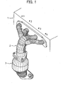
- Fig. 1 is a schematic perspective view of an engine and an exhaust manifold of a first embodiment according to the invention.
- An engine 1 is a four-cylinder engine where a firing (for example, spark or ignition) thereof is carried out in the order of cylinder # 1, cylinder # 3, cylinder # 4, and cylinder # 2.
- An exhaust manifold 2 is mounted to a cylinder head side and connected to an exhaust port outlet for each cylinder and a manifold catalyst 3 is mounted to an outlet of exhaust manifold 2.
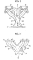
- Fig. 2 is an elevation view of exhaust manifold 2
- Fig. 3 is a plan view thereof
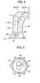
- Fig. 4 is a side view thereof
- Fig. 5 is a bottom view thereof.
- Exhaust manifold 2 comprises branches B 1 - B 4 connected respectively to the exhaust port outlet of each cylinder of engine 1 through a flange 21, a convergence branch W 1 where branch B 1 of cylinder # 1 and branch B 4 of cylinder # 4 that are not fired in succession and positioned at an outward side of a cylinder-in -line direction are convergent, a convergence branch W 2 where branch B 2 of cylinder # 2 and branch B 3 of cylinder # 3 that are not fired in succession and positioned at an inward side of a cylinder-in -line direction are convergent, and a collection portion (diffuser portion) DF where convergent branches W 1 and W 2 are further made convergent and expanded downwardly.
- a convergence branch W 1 where branch B 1 of cylinder # 1 and branch B 4 of cylinder # 4 that are not fired in succession and positioned at an outward side of a cylinder-in -line direction are convergent
- a convergence branch W 2 where branch B 2 of cylinder #
- Manifold catalyst 3 is mounted to an outlet of collection portion DF through a flange 22.
- Branch B 1 of cylinder # 1 and branch B 4 of cylinder # 4 extend in an inward and slanting, downward direction and then, are convergent where its convergence angle ( an angle that two center axis lines of branch B 1 and branch B 4 form at a convergence point thereof) ⁇ 1 is equal to or below 20 degrees.
- Branch B 2 of cylinder # 2 and branch B 3 of cylinder # 3 positioned inwardly are oppositely and laterally projected from the exhaust port outlet and get convergent at a minimum length from a plan view where a convergence angle ⁇ 2 thereof is made below 20 degrees by disposing a partition wall 23.
- Convergent branch W 1 of branch B 1 and B 4 positioned outwardly is placed between engine 1 and convergent branch W 2 of branch B 2 and B 3 positioned inwardly and convergent branch W 1 is substantially parallel to convergent branch W 2.
- convergent branch W 2 is convergent at a more upstream side, thereby forming one straight pipe.
- These convergent branches W 1, W 2 are opened to collection portion DF with W 1 and W 2 being kept in parallel and get convergent therein (Fig. 4) where the convergence angle ⁇ 3 is 0 degrees due to a center axis C-W 1 of W 1 and a center axis C-W 2 of W 2 being in parallel, but may be equal to or below 20 degrees.
- Collection portion DF is expanded in diameter downwardly and a mounting bore 24 for an air-fuel ratio sensor (02 sensor) is formed in an intermediate outer wall thereof.
- the air-fuel ratio sensor is positioned within a plane in parallel with the partition wall between convergent branches W 1 and W 2 opened to collection portion DF with reference to Fig. 5.
- branch B 1 of cylinder # 1 and branch B 4 of cylinder # 4 that are not fired in succession and have little exhaust gas interference with each other become convergent at a distance as short as possible and so are branch B 2 of cylinder # 2 and branch B 3 of cylinder # 3. Accordingly, a total length of an exhaust manifold can be shortened without a torque reduction at low and intermediate speed ranges.
- Branch B 2 of cylinder # 2 and branch B 3 of cylinder # 3 positioned inwardly are oppositely and laterally projected from the exhaust port outlet and get convergent at a minimum length and after convergence thereof, convergence branch W 2 is formed of one single manifold. Therefore, a total length of the exhaust manifold is minimized.
- convergent branch W 1 after convergence, is formed of one single straight pipe, permitting a minimum total length of the exhaust manifold.
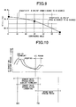
- Fig. 6 (a) shows a relationship between a total length of an exhaust manifold and an exhaust gas temperature (especially, an exhaust gas temperature immediately before the manifold catalyst in a lapse of 15 minutes after the engine is started).
- the exhaust gas temperature immediately before the manifold catalyst can rise up to from 270 degrees to 320 degrees.
- the total length of the exhaust manifold is represented as a total length of each exhaust manifold branch and each convergence branch from each cylinder to a manifold catalyst.
- Fig. 7 shows a relationship between an exhaust gas temperature immediately before the manifold catalyst in 15 minutes after an engine is started and HC emission amount at a manifold catalyst outlet during the same period of time (15 minutes) where due to improvement of temperature rise performance of the manifold catalyst after the engine is started (from 270 degrees C to 320 degrees C), a catalyst activation is promoted and HC emission amount can be reduced.
- the convergence portion of the branches is formed of a shape such that the propagation path of the exhaust pulsation makes it difficult to go around into another exhaust manifold for a convergence angle of the branches equal to or below 20 degrees, thereby improving exhaust emission.
- an exhaust gas pulsation pressure at the exhaust port outlet of cylinder # 1 is respectively measured. It is confirmed from this measurement that the exhaust gas pulsation pressure in the vicinity of a valve overlap period from an intake valve opening timing to an exhaust valve closing timing is lowered more as the convergence angle is made small, permitting decrease of the exhaust gas interference and also in case of the convergence angle being equal to or below 30 degrees, a level of the exhaust gas interference substantially as low as in a case of the convergence of 0 degrees can be achieved.
- Fig. 9 shows a relationship between a convergence angle and an intake volumetric efficiency ( ⁇ v) where in the range of from 30 degrees to 60 degrees as a convergence angle, an intake volumetric efficiency decreases by 0.17% each time for an increase of 10 degrees (sensitivity - 0.17 %/10 degrees) and in a case of from 0 degrees to 20 degrees as a convergence angle, an intake volumetric efficiency decreases by 0.05% each time for an increase of 10 degrees (sensitivity - 0.05 % /10 degrees).
- the present invention in view of this result, properly reduces an exhaust gas interference with a convergence angle equal to or below 20 degrees.
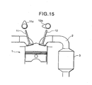
- opening timing and closing timing of an intake valve 11 and an exhaust valve 12 are determined by each cam profile of an intake valve driving cam 11 a and an exhaust valve driving cam 12a.
- An exhaust valve opening timing is normally about 45 degrees before bottom dead center, but by setting it in the range of 0 degree - 30 degrees before bottom dead center, timing of the blowdown wave is delayed as shown in a dotted line compared to an earlier technology in a solid line as shown in Fig. 10.
- a blowdown wave in cylinder # 2 reaches an exhaust valve head of cylinder # 3 and returns back to cylinder # 2 as a reflection wave after the overlap period of intake and exhaust valves 11,12 in cylinder # 2, thereby improving the exhaust gas interference during the valve overlap period and the output torque at low and intermediate speed ranges.
- Change of the exhaust valve opening timing can be made by shortening an operating angle of exhaust valve driving cam 12a, varying an operating angle of exhaust valve 12, varying an operating angle and a lift amount of exhaust valve 12, varying an operating center angle of exhaust valve 12, and so on.
- Fig. 11 shows an improvement effect of an intake volumetric efficiency due to an exhaust gas interference reduction.
- Fig. 12 shows a reduction effect of a remaining gas rate. Since in any of them, a scavenging efficiency improves due to the exhaust gas interference reduction at low and intermediate speed ranges, the intake volumetric efficiency improves and as a result, the remaining gas efficiency improves.
- an engine output performance improves and by reduction of the remaining gas efficiency, a combustion temperature decreases, thereby improving a knocking performance.
- a bend ratio of a manifold diameter of an exhaust manifold branch is set as equal to or more than 1.5 or an expanding angle of a collection portion (diffuser portion) is set as equal to or less than 60 degrees.
- delay of an exhaust valve opening timing may be made only at low and intermediate speed ranges (for example, below 4000rpm).
- a mounting position of an air-fuel ratio sensor will be explained. It becomes easy to narrow tuning factors for finding out an optimal position of an air-fuel ratio sensor in terms of cylinder sensitivity of the sensor caused by forming a straight manifold portion in convergent branch W 1 of cylinder # 1 and cylinder # 4 and convergent branch W 2 of cylinder # 2 and cylinder # 3. Accordingly, an optimal position of the air-fuel ratio sensor can be determined with a little man-hour.
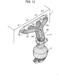
- Fig. 13 is a schematic perspective view of an engine and an exhaust manifold of a second embodiment according to the invention.
- the second embodiment is different from the first embodiment in that convergent branch W 2 of branch B 2 of cylinder # 2 and branch B 3 of cylinder # 3 is placed between the engine and convergent branch W 1 of branch B 1 of # 1 cylinder and branch B 4 of cylinder # 4 and is the same as in the rest thereof.
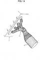
- Fig. 14 is a schematic perspective view of an engine and an exhaust manifold of a third embodiment according to the invention.
- the engine is placed in a lateral direction of a vehicle and an exhaust system is disposed in a front side of the vehicle.
- the exhaust system is disposed in a rear side of the vehicle.
- two exhaust manifold branches of two cylinders that are not fired in succession are made convergent in a convergence angle equal to or below 20 degrees and subsequently the two convergent branches are further made convergent.
- the exhaust manifold branches of the cylinders that have no problem with exhaust gas interference by the pressure wave of the exhaust gases are made convergent in a relatively upstream side thereof and the convergence angle is made equal to or below 20 degrees for preventing the pressure of the exhaust gases of the one cylinder side from going around into the other cylinder side.
- the four-cylinder engine is fired in order of cylinder # 1, cylinder # 3, cylinder # 4, and cylinder # 2 where the two exhaust manifold branches of cylinder # 1 and cylinder # 4, as well as of cylinder # 2 and cylinder # 3, that are not fired in succession get respectively convergent, and thus, the two cylinders ( cylinders # 1 and # 4) in the outward side of a cylinder-in -line direction are convergent and the two cylinders (cylinders # 2 and # 3) in the inward side thereof are independently made convergent before the entire exhaust manifold branches are convergent.
- the layout of the exhaust manifold is simple and the cylinders in the inward side can be made convergent more upstream.
- the independent portion of the exhaust manifold can be shortened and the temperature rise performance of the exhaust catalyst is improved.
- the two manifold branches of the cylinder # 2 and cylinder # 3 are projected in an opposite and lateral direction and subsequently are made convergent, namely, the two manifold branches are of lateral shape projecting from each port outlet of the cylinders into each other's port outlet. Accordingly, the manifold branches can be convergent at a minimum distance and a total length of the exhaust manifold is minimized. Therefore, a catalyst activation time can be shortened a lot more.
- the two exhaust manifold branches of cylinder # 1 and cylinder # 4, as well as of cylinder # 2 and cylinder # 3, that are not fired in succession get respectively convergent and subsequently the two convergent branches are made convergent.
- the convergence position of the two exhaust manifold branches of cylinder # 2 and cylinder # 3 is placed upstream of the convergence position of the two exhaust manifold branches of cylinder # 1 and cylinder # 4.
- the exhaust manifold branches of the cylinders that have no problem with exhaust gas interference by the pressure wave of the exhaust gases are made convergent in a relatively upstream side thereof and the two cylinders (# 2 cylinder and # 3 cylinder) in the inward side that can be convergent in a more upstream side in view of a layout is made convergent before the two other cylinders ( cylinders # 1 and # 4).
- the convergent branch after the two exhaust manifold branches of cylinder # 2 and cylinder # 3 are convergent is formed of one straight pipe, a total length of the exhaust manifold is shortened and temperature rise performance of the manifold catalyst after the engine is started can be improved.
- the two manifold branches of cylinder # 2 and cylinder # 3 can be convergent at a minimum distance and a total length of the exhaust manifold is minimized. Therefore, a catalyst activation time can be shortened greatly.
- each convergence angle of the exhaust manifold branches of cylinder # 1 and cylinder # 4 and cylinder # 2 and cylinder # 3 is equal to or below 20 degrees and further a convergence angle of the two convergent branches is equal to or below 20 degrees.
- one of the embodiments preferably refers to an engine comprising: four cylinders #1, #2, #3, #4; and at least four exhaust manifold branches B1,B2,B3,B4 included in the exhaust manifold 2 and arranged to each cylinder #1,#2,#3,#4, wherein two exhaust manifold branches B1,B4 of two cylinders #1,#4 that are not fired in succession are convergent at a convergence angle equal to or below 20 degrees to form a first convergent exhaust manifold branch W1, two exhaust manifold branches B2,B3 of another two cylinders #2,#3 that are not fired in succession are convergent at a convergence angle equal to or below 20 degrees to form a second convergent exhaust manifold branch W2, and the first convergent
- the first convergent exhaust manifold branch W1 and the second convergent exhaust manifold branch W2 are convergent at a convergence angle equal to or below 20 degrees.
- the four cylinders line up in order of cylinder # 1, cylinder # 2, cylinder # 3, and cylinder # 4, the four cylinders being fired in order of cylinder # 1, cylinder # 3, cylinder # 4, and cylinder # 2, the two exhaust manifold branches B1 ,B4 of the cylinder # 1 and the cylinder # 4 arranged at both ends in a cylinder-in-line direction of the engine 1 are convergent, and the two exhaust manifold branches B2,B3 of the cylinder # 2 and the cylinder # 3 arranged between the cylinder # 1 and the cylinder # 4 in the cylinder-in-line direction of the engine 1 are convergent.
- the second convergent exhaust manifold branch W2 is formed such that the two exhaust manifold branches B2,B3 of the cylinder # 2 and the cylinder # 3 are projected toward each other and substantially along the cylinder-in-line direction, and are thereafter convergent.
- Another embodiment preferably refers to an engine comprising:
- the second convergent exhaust manifold branch W2 is formed of one straight pipe.
- the second convergent exhaust manifold branch W2 is formed such that the two exhaust manifold branches B2.B3 of the cylinder # 2 and the cylinder # 3 are projected toward each other and substantially along a cylinder-in-line direction, and are thereafter convergent.
- a convergence angle of the first convergent exhaust manifold branch W1, as well as a convergence angle of the second convergent exhaust manifold branch W2 are respectively equal to or below 20 degrees, and a convergence angle of the first and the second convergent exhaust manifold branches W1,W2 is equal to or below 20 degrees.
- an exhaust valve 12 disposed in a combustion chamber of the engine 1 that controls an exhaust gas from the combustion chamber wherein an exhaust valve opening timing of the exhaust valve 12 is set in the range of from 30 degrees before bottom dead center to the bottom dead center.
- temperature rise performance of a manifold catalyst improves by shortening a total length of the exhaust manifold while preventing exhaust gas interference between the cylinders.
- an exhaust manifold branch of cylinder # 1 and an exhaust manifold branch of cylinder # 4 in outward sides of the engine that are not fired in succession are made convergent with its convergence angle ⁇ 1 being equal to or below 20 degrees to form a first convergent exhaust manifold branch and an exhaust manifold branch of cylinder # 2 and an exhaust manifold branch of cylinder # 3 between the cylinder # 1 and cylinder # 4 that are not fired in succession are made convergent at a minimum distance having a laterally projected shape to form a second convergent exhaust manifold branch.
- the first and the second convergent exhaust manifold branches are thereafter convergent at a convergence angle ⁇ 3 from 0 degrees to 20 degrees.
- the invention properly prevents a wave pressure of the exhaust gas from going around-a convergence point of the exhaust manifold.
- timing of a blowdown is delayed by retarding an exhaust valve opening timing of an engine as beyond 30 degrees before bottom dead center.
- the invention is explained by using a four-cylinder engine, but the invention also can be applied to an eight-cylinder engine, for example, each four -cylinderV-type eight-cylinder engine.
Landscapes
- Engineering & Computer Science (AREA)
- Chemical & Material Sciences (AREA)
- Combustion & Propulsion (AREA)
- Mechanical Engineering (AREA)
- General Engineering & Computer Science (AREA)
- Chemical Kinetics & Catalysis (AREA)
- Health & Medical Sciences (AREA)
- Toxicology (AREA)
- Exhaust Silencers (AREA)
- Cylinder Crankcases Of Internal Combustion Engines (AREA)
- Exhaust Gas After Treatment (AREA)
- Output Control And Ontrol Of Special Type Engine (AREA)
Applications Claiming Priority (2)
| Application Number | Priority Date | Filing Date | Title |
|---|---|---|---|
| JP2002063605A JP2003262120A (ja) | 2002-03-08 | 2002-03-08 | 4気筒エンジンの排気マニホールド |
| EP03005140A EP1342890B1 (de) | 2002-03-08 | 2003-03-07 | Abgaskrümmer einer Abgasanlage für eine vier-Zylinder Brennkraftmaschine |
Related Parent Applications (1)
| Application Number | Title | Priority Date | Filing Date |
|---|---|---|---|
| EP03005140A Division EP1342890B1 (de) | 2002-03-08 | 2003-03-07 | Abgaskrümmer einer Abgasanlage für eine vier-Zylinder Brennkraftmaschine |
Publications (3)
| Publication Number | Publication Date |
|---|---|
| EP1659272A2 true EP1659272A2 (de) | 2006-05-24 |
| EP1659272A3 EP1659272A3 (de) | 2006-05-31 |
| EP1659272B1 EP1659272B1 (de) | 2007-08-15 |
Family
ID=27751254
Family Applications (2)
| Application Number | Title | Priority Date | Filing Date |
|---|---|---|---|
| EP03005140A Expired - Lifetime EP1342890B1 (de) | 2002-03-08 | 2003-03-07 | Abgaskrümmer einer Abgasanlage für eine vier-Zylinder Brennkraftmaschine |
| EP06000863A Expired - Lifetime EP1659272B1 (de) | 2002-03-08 | 2003-03-07 | Abgaskrümmer einer Abgasanlage für eine vier-Zylinder Brennkraftmaschine |
Family Applications Before (1)
| Application Number | Title | Priority Date | Filing Date |
|---|---|---|---|
| EP03005140A Expired - Lifetime EP1342890B1 (de) | 2002-03-08 | 2003-03-07 | Abgaskrümmer einer Abgasanlage für eine vier-Zylinder Brennkraftmaschine |
Country Status (5)
| Country | Link |
|---|---|
| US (2) | US6962049B2 (de) |
| EP (2) | EP1342890B1 (de) |
| JP (1) | JP2003262120A (de) |
| CN (1) | CN100575676C (de) |
| DE (2) | DE60305760T2 (de) |
Families Citing this family (34)
| Publication number | Priority date | Publication date | Assignee | Title |
|---|---|---|---|---|
| JP2003262120A (ja) * | 2002-03-08 | 2003-09-19 | Nissan Motor Co Ltd | 4気筒エンジンの排気マニホールド |
| DE10311235A1 (de) * | 2003-03-14 | 2004-10-14 | Emitec Gesellschaft Für Emissionstechnologie Mbh | Mehrsträngiges Abgassystem mit mindestens einem Messfühler, Wabenkörper mit einer Ausnehmung für mindestens einen Messfühler und Verfahren zum Betrieb eines mehrsträngigen Abgassystems |
| WO2006116788A2 (de) | 2005-05-03 | 2006-11-09 | Avl List Gmbh | Abgassystem für eine brennkraftmaschine |
| AT501797B1 (de) * | 2005-05-10 | 2008-02-15 | Avl List Gmbh | Abgassystem für eine brennkraftmaschine |
| US7874149B2 (en) * | 2005-08-17 | 2011-01-25 | Kawasaki Jukogyo Kabushiki Kaisha | Exhaust apparatus for vehicle, and motorcycle having the same |
| USD561079S1 (en) * | 2005-11-18 | 2008-02-05 | Workhorse Custom Chassis, Llc | Vehicle header |
| USD561078S1 (en) * | 2005-11-18 | 2008-02-05 | Workhorse Custom Chassis, Llc | Vehicle header |
| JP2007205174A (ja) * | 2006-01-31 | 2007-08-16 | Toyota Motor Corp | 内燃機関 |
| USD541302S1 (en) * | 2006-02-16 | 2007-04-24 | Indmar Products Company Inc. | Exhaust manifold |
| JP2008031868A (ja) * | 2006-07-26 | 2008-02-14 | Yamaha Marine Co Ltd | 8気筒エンジンにおける排気装置 |
| JP4525646B2 (ja) * | 2006-08-09 | 2010-08-18 | トヨタ自動車株式会社 | 内燃機関 |
| CN101070776B (zh) * | 2006-12-31 | 2011-01-19 | 潍柴动力股份有限公司 | 8缸直列柴油机多脉冲转换排气装置 |
| JP4748081B2 (ja) * | 2007-02-23 | 2011-08-17 | トヨタ自動車株式会社 | 内燃機関の排気装置 |
| EP2146068A1 (de) * | 2008-07-14 | 2010-01-20 | Ford Global Technologies, LLC, A subsidary of Ford Motor Company | Anordnung mit Zylinderkopf und Turbine |
| EP2172635B1 (de) * | 2008-10-02 | 2018-12-12 | Ford Global Technologies, LLC | Zylinderkopf für eine Brennkraftmaschine mit zwei integrierten Abgaskrümmern und Verfahren zum Betreiben einer Brennkraftmaschine mit einem derartigen Zylinderkopf |
| USD614104S1 (en) * | 2009-03-20 | 2010-04-20 | Indmar Products Company Inc. | Exhaust manifold |
| CN101940903A (zh) * | 2010-05-04 | 2011-01-12 | 姚光纯 | 一种通过脉冲压力波来改善催化反应的工艺方法 |
| KR101196305B1 (ko) * | 2010-05-25 | 2012-11-06 | 우신공업 주식회사 | 배기 매니폴드 |
| CN101956597A (zh) * | 2010-11-12 | 2011-01-26 | 重庆潍柴发动机厂 | 一种v型柴油机涡轮后二合一排气管 |
| JP5870488B2 (ja) | 2011-01-20 | 2016-03-01 | マツダ株式会社 | 多気筒エンジンの吸排気装置 |
| JP5791331B2 (ja) * | 2011-03-31 | 2015-10-07 | ダイハツ工業株式会社 | 触媒コンバータの排気導入管の構造 |
| US20130291816A1 (en) * | 2012-05-02 | 2013-11-07 | Tula Technology, Inc. | Using valve timing to improve engine acoustics |
| US9303555B2 (en) * | 2013-04-04 | 2016-04-05 | GM Global Technology Operations LLC | Exhaust manifold |
| CN103244250A (zh) * | 2013-05-27 | 2013-08-14 | 奇瑞汽车股份有限公司 | 一种vvt发动机排气歧管 |
| CN103644022A (zh) * | 2013-12-27 | 2014-03-19 | 淄博柴油机总公司 | 八缸直列发动机及其排气增压系统 |
| JP6311539B2 (ja) * | 2014-09-01 | 2018-04-18 | マツダ株式会社 | 多気筒エンジンの排気装置 |
| WO2016035154A1 (ja) * | 2014-09-03 | 2016-03-10 | 日産自動車株式会社 | 内燃機関の排気装置 |
| EP3190279B1 (de) * | 2014-09-03 | 2019-05-08 | Nissan Motor Co., Ltd | Abgasvorrichtung für einen verbrennungsmotor |
| WO2016035155A1 (ja) * | 2014-09-03 | 2016-03-10 | 日産自動車株式会社 | 内燃機関の排気装置 |
| US10240507B2 (en) * | 2014-10-09 | 2019-03-26 | Nissan Motor Co., Ltd. | Exhaust device for four-cylinder internal combustion engine |
| US9528425B2 (en) * | 2014-11-26 | 2016-12-27 | Hyundai Motor Company | Exhaust system structure for improving noise problem |
| CN106321210A (zh) * | 2016-09-26 | 2017-01-11 | 安徽江淮汽车股份有限公司 | 降低发动机各气缸间排气干扰的排气结构 |
| JP6972754B2 (ja) * | 2017-08-10 | 2021-11-24 | スズキ株式会社 | 内燃機関の排気構造 |
| CN109296435B (zh) * | 2018-09-06 | 2024-07-05 | 中国第一汽车股份有限公司 | 一种改善发动机冷态启动排放的排气歧管结构 |
Family Cites Families (29)
| Publication number | Priority date | Publication date | Assignee | Title |
|---|---|---|---|---|
| US4022019A (en) * | 1970-11-20 | 1977-05-10 | Alfa Romeo S.P.A. | Exhaust conveying system for internal combustion engines |
| JPS5844211A (ja) | 1981-09-09 | 1983-03-15 | Yamaha Motor Co Ltd | エンジンの排気ガス浄化装置 |
| JPS5865562U (ja) * | 1981-10-26 | 1983-05-04 | 日産自動車株式会社 | デユアルマニホ−ルドの酸素センサ取付部構造 |
| JPH0224897Y2 (de) | 1985-05-20 | 1990-07-09 | ||
| JPH0166424U (de) | 1987-10-22 | 1989-04-27 | ||
| JPH0543227Y2 (de) * | 1987-12-21 | 1993-10-29 | ||
| JPH0618033Y2 (ja) | 1989-01-30 | 1994-05-11 | 株式会社大力鉄工所 | エンジンの排気マニホールド構造 |
| JPH0723533Y2 (ja) | 1989-02-03 | 1995-05-31 | 本田技研工業株式会社 | エンジン用排気マニホールド構造 |
| JPH0444438U (de) | 1990-08-21 | 1992-04-15 | ||
| JP2567447Y2 (ja) | 1991-01-31 | 1998-04-02 | マツダ株式会社 | エンジンの排気装置 |
| JP2579731Y2 (ja) | 1991-06-05 | 1998-08-27 | 三恵工業株式会社 | 自動車エンジン等のエキゾーストマニホルド |
| JP2582723Y2 (ja) | 1991-09-03 | 1998-10-08 | スズキ株式会社 | 自動車の排気装置 |
| DE69327646T2 (de) * | 1992-02-17 | 2000-11-16 | Alexander Chabry | Ein- und auslassvorrichtung für brennkraftmaschine |
| JPH0783048A (ja) | 1993-09-17 | 1995-03-28 | Suzuki Motor Corp | 自動車の排気マニホールド |
| DE19505710C2 (de) * | 1994-02-21 | 2002-10-17 | Aisin Takaoka Ltd | Auspuffkrümmer |
| JPH07324622A (ja) | 1994-05-30 | 1995-12-12 | Yamaha Motor Co Ltd | 多気筒エンジンの排気マニホルド |
| DE19510602C1 (de) * | 1995-03-23 | 1996-04-11 | Daimler Benz Ag | Fächerartiger Abgaskrümmer für mehrzylindrige Brennkraftmaschinen |
| JP3334454B2 (ja) * | 1995-04-03 | 2002-10-15 | トヨタ自動車株式会社 | エキゾーストマニホルド集合部構造 |
| JPH0968038A (ja) | 1995-08-28 | 1997-03-11 | Aisin Takaoka Ltd | 内燃機関の排気マニホールド |
| JPH1026037A (ja) * | 1996-07-09 | 1998-01-27 | Yutaka Giken Co Ltd | センサ取付ボス |
| JPH10331632A (ja) * | 1997-05-30 | 1998-12-15 | Suzuki Motor Corp | 内燃機関の排気マニホルド装置 |
| US6122911A (en) * | 1998-09-28 | 2000-09-26 | Honda Giken Kogyo Kabushiki Kaisha | Exhaust manifold pipe weld assembly |
| US6199376B1 (en) * | 1998-09-28 | 2001-03-13 | Honda Giken Kogyo Kabushiki Kaisha | Extension of exhaust manifold conduit into exhaust pipe |
| JP2000230424A (ja) * | 1999-02-09 | 2000-08-22 | Hyundai Motor Co Ltd | ガソリンエンジン用排気マニホールド |
| JP2000337143A (ja) | 1999-05-28 | 2000-12-05 | Yutaka Giken Co Ltd | 複数気筒エンジンの排気マニホールド |
| DE10002240B4 (de) * | 2000-01-20 | 2007-12-20 | Heinrich Gillet Gmbh | Vorrichtung zum Erzeugen eines obertonreichen sportlichen Auspuffgeräusches |
| JP3521895B2 (ja) * | 2000-12-07 | 2004-04-26 | 日産自動車株式会社 | 内燃機関の排気マニホルド |
| KR20030027401A (ko) * | 2001-09-28 | 2003-04-07 | 현대자동차주식회사 | 자동차의 배기매니폴드구조 |
| JP2003262120A (ja) * | 2002-03-08 | 2003-09-19 | Nissan Motor Co Ltd | 4気筒エンジンの排気マニホールド |
-
2002
- 2002-03-08 JP JP2002063605A patent/JP2003262120A/ja active Pending
-
2003
- 2003-03-06 US US10/379,681 patent/US6962049B2/en not_active Expired - Fee Related
- 2003-03-07 CN CN03120209A patent/CN100575676C/zh not_active Expired - Fee Related
- 2003-03-07 EP EP03005140A patent/EP1342890B1/de not_active Expired - Lifetime
- 2003-03-07 DE DE60305760T patent/DE60305760T2/de not_active Expired - Lifetime
- 2003-03-07 EP EP06000863A patent/EP1659272B1/de not_active Expired - Lifetime
- 2003-03-07 DE DE60315733T patent/DE60315733T2/de not_active Expired - Lifetime
-
2005
- 2005-09-12 US US11/223,105 patent/US7520127B2/en not_active Expired - Fee Related
Also Published As
| Publication number | Publication date |
|---|---|
| DE60305760D1 (de) | 2006-07-20 |
| DE60315733T2 (de) | 2007-12-06 |
| DE60315733D1 (de) | 2007-09-27 |
| JP2003262120A (ja) | 2003-09-19 |
| DE60305760T2 (de) | 2006-10-19 |
| CN100575676C (zh) | 2009-12-30 |
| EP1342890A3 (de) | 2003-11-12 |
| EP1342890A2 (de) | 2003-09-10 |
| EP1342890B1 (de) | 2006-06-07 |
| US7520127B2 (en) | 2009-04-21 |
| US20030167759A1 (en) | 2003-09-11 |
| US20060005535A1 (en) | 2006-01-12 |
| CN1443931A (zh) | 2003-09-24 |
| EP1659272B1 (de) | 2007-08-15 |
| US6962049B2 (en) | 2005-11-08 |
| EP1659272A3 (de) | 2006-05-31 |
Similar Documents
| Publication | Publication Date | Title |
|---|---|---|
| EP1659272B1 (de) | Abgaskrümmer einer Abgasanlage für eine vier-Zylinder Brennkraftmaschine | |
| US5239960A (en) | Engine induction system provided with a mechanical supercharger | |
| US9341102B2 (en) | Conformal transverse muffler | |
| JP4394868B2 (ja) | エンジンの排気装置 | |
| EP0182223A2 (de) | Einlasssystem für einen Verbrennungsmotor | |
| CN103080506B (zh) | 多气缸火花点火引擎 | |
| US4671217A (en) | Intake system for internal combustion engine | |
| US10287937B2 (en) | Exhaust system for an engine | |
| US8936133B2 (en) | Four cycle internal combustion engine exhaust | |
| CN100478549C (zh) | 多汽缸内燃机 | |
| US6374599B1 (en) | Compact tuned exhaust system for aircraft with reciprocating engines | |
| JP4414930B2 (ja) | 4気筒エンジンの排気マニホールド | |
| JP2754978B2 (ja) | 6気筒内燃機関の制御装置 | |
| JP2000248948A (ja) | エンジンの排気制御方法とその装置 | |
| CN100383370C (zh) | 用于多缸内燃机的控制装置 | |
| JP2010084530A5 (de) | ||
| JP2010084530A (ja) | エンジンの排気制御装置 | |
| JP6979315B2 (ja) | エンジン制御装置 | |
| JP2015212532A (ja) | 内燃機関の制御装置 | |
| JPS62101829A (ja) | エンジンの吸気装置 | |
| US20080034852A1 (en) | Intake manifold assembly | |
| US20170211587A1 (en) | Compressor housing | |
| JPH01208514A (ja) | エンジンの排気装置 | |
| JPH0192520A (ja) | エンジンの吸気装置 | |
| JPH01257717A (ja) | 5気筒エンジン用排気マニホールド |
Legal Events
| Date | Code | Title | Description |
|---|---|---|---|
| PUAI | Public reference made under article 153(3) epc to a published international application that has entered the european phase |
Free format text: ORIGINAL CODE: 0009012 |
|
| PUAL | Search report despatched |
Free format text: ORIGINAL CODE: 0009013 |
|
| 17P | Request for examination filed |
Effective date: 20060116 |
|
| AC | Divisional application: reference to earlier application |
Ref document number: 1342890 Country of ref document: EP Kind code of ref document: P |
|
| AK | Designated contracting states |
Kind code of ref document: A2 Designated state(s): DE FR GB |
|
| AK | Designated contracting states |
Kind code of ref document: A3 Designated state(s): DE FR GB |
|
| AKX | Designation fees paid |
Designated state(s): DE FR GB |
|
| 17Q | First examination report despatched |
Effective date: 20070111 |
|
| GRAP | Despatch of communication of intention to grant a patent |
Free format text: ORIGINAL CODE: EPIDOSNIGR1 |
|
| GRAS | Grant fee paid |
Free format text: ORIGINAL CODE: EPIDOSNIGR3 |
|
| GRAA | (expected) grant |
Free format text: ORIGINAL CODE: 0009210 |
|
| AC | Divisional application: reference to earlier application |
Ref document number: 1342890 Country of ref document: EP Kind code of ref document: P |
|
| AK | Designated contracting states |
Kind code of ref document: B1 Designated state(s): DE FR GB |
|
| REG | Reference to a national code |
Ref country code: GB Ref legal event code: FG4D |
|
| REF | Corresponds to: |
Ref document number: 60315733 Country of ref document: DE Date of ref document: 20070927 Kind code of ref document: P |
|
| ET | Fr: translation filed | ||
| PLBE | No opposition filed within time limit |
Free format text: ORIGINAL CODE: 0009261 |
|
| STAA | Information on the status of an ep patent application or granted ep patent |
Free format text: STATUS: NO OPPOSITION FILED WITHIN TIME LIMIT |
|
| 26N | No opposition filed |
Effective date: 20080516 |
|
| PGFP | Annual fee paid to national office [announced via postgrant information from national office to epo] |
Ref country code: FR Payment date: 20140311 Year of fee payment: 12 |
|
| PGFP | Annual fee paid to national office [announced via postgrant information from national office to epo] |
Ref country code: GB Payment date: 20140305 Year of fee payment: 12 |
|
| PGFP | Annual fee paid to national office [announced via postgrant information from national office to epo] |
Ref country code: DE Payment date: 20140417 Year of fee payment: 12 |
|
| REG | Reference to a national code |
Ref country code: DE Ref legal event code: R119 Ref document number: 60315733 Country of ref document: DE |
|
| GBPC | Gb: european patent ceased through non-payment of renewal fee |
Effective date: 20150307 |
|
| REG | Reference to a national code |
Ref country code: FR Ref legal event code: ST Effective date: 20151130 |
|
| PG25 | Lapsed in a contracting state [announced via postgrant information from national office to epo] |
Ref country code: GB Free format text: LAPSE BECAUSE OF NON-PAYMENT OF DUE FEES Effective date: 20150307 Ref country code: DE Free format text: LAPSE BECAUSE OF NON-PAYMENT OF DUE FEES Effective date: 20151001 |
|
| PG25 | Lapsed in a contracting state [announced via postgrant information from national office to epo] |
Ref country code: FR Free format text: LAPSE BECAUSE OF NON-PAYMENT OF DUE FEES Effective date: 20150331 |