EP1666973A1 - Lithographischer Apparat und Verfahren zur Herstellung einer Vorrichtung - Google Patents
Lithographischer Apparat und Verfahren zur Herstellung einer Vorrichtung Download PDFInfo
- Publication number
- EP1666973A1 EP1666973A1 EP05257182A EP05257182A EP1666973A1 EP 1666973 A1 EP1666973 A1 EP 1666973A1 EP 05257182 A EP05257182 A EP 05257182A EP 05257182 A EP05257182 A EP 05257182A EP 1666973 A1 EP1666973 A1 EP 1666973A1
- Authority
- EP
- European Patent Office
- Prior art keywords
- substrate
- liquid
- inlet
- outlet
- space
- Prior art date
- Legal status (The legal status is an assumption and is not a legal conclusion. Google has not performed a legal analysis and makes no representation as to the accuracy of the status listed.)
- Granted
Links
Images


Classifications
-
- G—PHYSICS
- G03—PHOTOGRAPHY; CINEMATOGRAPHY; ANALOGOUS TECHNIQUES USING WAVES OTHER THAN OPTICAL WAVES; ELECTROGRAPHY; HOLOGRAPHY
- G03F—PHOTOMECHANICAL PRODUCTION OF TEXTURED OR PATTERNED SURFACES, e.g. FOR PRINTING, FOR PROCESSING OF SEMICONDUCTOR DEVICES; MATERIALS THEREFOR; ORIGINALS THEREFOR; APPARATUS SPECIALLY ADAPTED THEREFOR
- G03F7/00—Photomechanical, e.g. photolithographic, production of textured or patterned surfaces, e.g. printing surfaces; Materials therefor, e.g. comprising photoresists; Apparatus specially adapted therefor
- G03F7/70—Microphotolithographic exposure; Apparatus therefor
- G03F7/70216—Mask projection systems
- G03F7/70341—Details of immersion lithography aspects, e.g. exposure media or control of immersion liquid supply
-
- G—PHYSICS
- G03—PHOTOGRAPHY; CINEMATOGRAPHY; ANALOGOUS TECHNIQUES USING WAVES OTHER THAN OPTICAL WAVES; ELECTROGRAPHY; HOLOGRAPHY
- G03F—PHOTOMECHANICAL PRODUCTION OF TEXTURED OR PATTERNED SURFACES, e.g. FOR PRINTING, FOR PROCESSING OF SEMICONDUCTOR DEVICES; MATERIALS THEREFOR; ORIGINALS THEREFOR; APPARATUS SPECIALLY ADAPTED THEREFOR
- G03F7/00—Photomechanical, e.g. photolithographic, production of textured or patterned surfaces, e.g. printing surfaces; Materials therefor, e.g. comprising photoresists; Apparatus specially adapted therefor
- G03F7/20—Exposure; Apparatus therefor
- G03F7/2041—Exposure; Apparatus therefor in the presence of a fluid, e.g. immersion; using fluid cooling means
-
- G—PHYSICS
- G03—PHOTOGRAPHY; CINEMATOGRAPHY; ANALOGOUS TECHNIQUES USING WAVES OTHER THAN OPTICAL WAVES; ELECTROGRAPHY; HOLOGRAPHY
- G03F—PHOTOMECHANICAL PRODUCTION OF TEXTURED OR PATTERNED SURFACES, e.g. FOR PRINTING, FOR PROCESSING OF SEMICONDUCTOR DEVICES; MATERIALS THEREFOR; ORIGINALS THEREFOR; APPARATUS SPECIALLY ADAPTED THEREFOR
- G03F7/00—Photomechanical, e.g. photolithographic, production of textured or patterned surfaces, e.g. printing surfaces; Materials therefor, e.g. comprising photoresists; Apparatus specially adapted therefor
- G03F7/70—Microphotolithographic exposure; Apparatus therefor
- G03F7/708—Construction of apparatus, e.g. environment aspects, hygiene aspects or materials
- G03F7/70808—Construction details, e.g. housing, load-lock, seals or windows for passing light in or out of apparatus
Definitions
- the present invention relates to a lithographic apparatus and a method for manufacturing a device.
- a lithographic apparatus is a machine that applies a desired pattern onto a substrate, usually onto a target portion of the substrate.
- a lithographic apparatus can be used, for example, in the manufacture of integrated circuits (ICs).
- a patterning device which is alternatively referred to as a mask or a reticle, may be used to generate a circuit pattern to be formed on an individual layer of the IC.
- This pattern can be transferred onto a target portion (e.g. comprising part of, one, or several dies) on a substrate (e.g. a silicon wafer). Transfer of the pattern is typically via imaging onto a layer of radiation-sensitive material (resist) provided on the substrate.
- resist radiation-sensitive material
- a single substrate will contain a network of adjacent target portions that are successively patterned.
- lithographic apparatus include so-called steppers, in which each target portion is irradiated by exposing an entire pattern onto the target portion at one time, and so-called scanners, in which each target portion is irradiated by scanning the pattern through a radiation beam in a given direction (the "scanning"-direction) while synchronously scanning the substrate parallel or anti-parallel to this direction. It is also possible to transfer the pattern from the patterning device to the substrate by imprinting the pattern onto the substrate.
- liquid supply system to provide liquid on only a localized area of the substrate and in between the final element of the projection system and the substrate (the substrate generally has a larger surface area than the final element of the projection system).
- the substrate generally has a larger surface area than the final element of the projection system.
- liquid is supplied by at least one inlet IN onto the substrate, preferably along the direction of movement of the substrate relative to the final element, and is removed by at least one outlet OUT after having passed under the projection system. That is, as the substrate is scanned beneath the element in a -X direction, liquid is supplied at the +X side of the element and taken up at the -X side.
- Figure 2 shows the arrangement schematically in which liquid is supplied via inlet IN and is taken up on the other side of the element by outlet OUT which is connected to a low pressure source.
- the liquid is supplied along the direction of movement of the substrate relative to the final element, though this does not need to be the case.
- Figure 3 shows the arrangement schematically in which liquid is supplied via inlet IN and is taken up on the other side of the element by outlet OUT which is connected to a low pressure source.
- the liquid is supplied along the direction of movement of the substrate relative to the final element, though this does not need to be the case.
- Figure 3 shows the arrangement schematically in which liquid is supplied via inlet IN and is taken up on the other side of the element by outlet OUT which is connected to a low pressure source.
- lithographic apparatus having a liquid supply system wherein a substrate may be moved in different directions without having to switch a flow direction of the liquid between the projection system of the lithographic apparatus and a substrate.
- a lithographic apparatus comprising:
- an illumination system configured to condition a beam of radiation
- a support structure configured to hold a patterning device, the patterning device configured to impart the beam with a pattern in its cross-section;
- a substrate table configured to hold a substrate
- a projection system configured to project the patterned beam onto a target portion of the substrate
- a liquid supply system comprising an inlet configured to supply a liquid to a space between the projection system and the substrate and an outlet configured to remove at least part of the liquid, the liquid supply system configured to rotate the inlet, the outlet, or both, about an axis substantially perpendicular to an exposure plane of the substrate.
- a lithographic apparatus comprising:
- an illumination system configured to condition a beam of radiation
- a support structure configured to hold a patterning device, the patterning device configured to impart the beam with a pattern in its cross-section;
- a substrate table configured to hold a substrate
- a projection system configured to project the patterned beam onto a target portion of the substrate
- a liquid supply system comprising an inlet configured to supply a liquid to a space between the projection system and the substrate and an outlet configured to remove at least part of the liquid, the liquid supply system configured to rotate the inlet and outlet in tandem about an axis substantially parallel to an optical axis of the projection system in accordance with a change in movement of the substrate.
- a device manufacturing method comprising:
- Figure 1 depicts a lithographic apparatus according to an embodiment of the invention
- Figures 2 and 3 depict a liquid supply system for use in a lithographic projection apparatus
- Figure 4 depicts another liquid supply system for use in a lithographic projection apparatus
- Figure 5 depicts another liquid supply system for use in a lithographic projection apparatus
- Figure 6 depicts a top view of a liquid supply system according to an embodiment of the invention.
- Figure 7 depicts a side view of the liquid supply system of Figure 6;
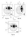
- Figures 8a to 8c depict various rotations of a liquid confinement structure according to an embodiment of the invention.
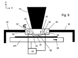
- Figure 9 depicts a side view of a liquid supply system according to another embodiment of the invention.
- Figure 1 schematically depicts a lithographic apparatus according to one embodiment of the invention.
- the apparatus comprises:
- the illumination system may include various types of optical components, such as refractive, reflective, magnetic, electromagnetic, electrostatic or other types of optical components, or any combination thereof, for directing, shaping, or controlling radiation.
- optical components such as refractive, reflective, magnetic, electromagnetic, electrostatic or other types of optical components, or any combination thereof, for directing, shaping, or controlling radiation.
- the support structure supports, i.e. bears the weight of, the patterning device. It holds the patterning device in a manner that depends on the orientation of the patterning device, the design of the lithographic apparatus, and other conditions, such as for example whether or not the patterning device is held in a vacuum environment.
- the support structure can use mechanical, vacuum, electrostatic or other clamping techniques to hold the patterning device.
- the support structure may be a frame or a table, for example, which may be fixed or movable as required.
- the support structure may ensure that the patterning device is at a desired position, for example with respect to the projection system. Any use of the terms "reticle” or “mask” herein may be considered synonymous with the more general term "patterning device.”
- patterning device used herein should be broadly interpreted as referring to any device that can be used to impart a radiation beam with a pattern in its cross-section such as to create a pattern in a target portion of the substrate. It should be noted that the pattern imparted to the radiation beam may not exactly correspond to the desired pattern in the target portion of the substrate, for example if the pattern includes phase-shifting features or so called assist features. Generally, the pattern imparted to the radiation beam will correspond to a particular functional layer in a device being created in the target portion, such as an integrated circuit.
- the patterning device may be transmissive or reflective.
- Examples of patterning devices include masks, programmable mirror arrays, and programmable LCD panels.
- Masks are well known in lithography, and include mask types such as binary, alternating phase-shift, and attenuated phase-shift, as well as various hybrid mask types.
- An example of a programmable mirror array employs a matrix arrangement of small mirrors, each of which can be individually tilted so as to reflect an incoming radiation beam in different directions. The tilted mirrors impart a pattern in a radiation beam which is reflected by the mirror matrix.
- projection system used herein should be broadly interpreted as encompassing any type of projection system, including refractive, reflective, catadioptric, magnetic, electromagnetic and electrostatic optical systems, or any combination thereof, as appropriate for the exposure radiation being used, or for other factors such as the use of an immersion liquid or the use of a vacuum. Any use of the term “projection lens” herein may be considered as synonymous with the more general term “projection system”.
- the apparatus is of a transmissive type (e.g. employing a transmissive mask).
- the apparatus may be of a reflective type (e.g. employing a programmable mirror array of a type as referred to above, or employing a reflective mask).
- the lithographic apparatus may be of a type having two (dual stage) or more substrate tables (and/or two or more mask tables). In such "multiple stage” machines the additional tables may be used in parallel, or preparatory steps may be carried out on one or more tables while one or more other tables are being used for exposure.
- the illuminator IL receives a radiation beam from a radiation source SO.
- the source and the lithographic apparatus may be separate entities, for example when the source is an excimer laser. In such cases, the source is not considered to form part of the lithographic apparatus and the radiation beam is passed from the source SO to the illuminator IL with the aid of a beam delivery system BD comprising, for example, suitable directing mirrors and/or a beam expander. In other cases the source may be an integral part of the lithographic apparatus, for example when the source is a mercury lamp.
- the source SO and the illuminator IL, together with the beam delivery system BD if required, may be referred to as a radiation system.
- the illuminator IL may comprise an adjuster AD for adjusting the angular intensity distribution of the radiation beam.
- an adjuster AD for adjusting the angular intensity distribution of the radiation beam.
- the illuminator IL may comprise various other components, such as an integrator IN and a condenser CO.
- the illuminator may be used to condition the radiation beam, to have a desired uniformity and intensity distribution in its cross-section.
- the radiation beam PB is incident on the patterning device (e.g., mask MA), which is held on the support structure (e.g., mask table MT), and is patterned by the patterning device. Having traversed the mask MA, the radiation beam PB passes through the projection system PL, which focuses the beam onto a target portion C of the substrate W.
- a liquid confinement structure IH which is described further below, supplies immersion liquid to a space between the final element of the projection system PL and the substrate W.
- the substrate table WT can be moved accurately, e.g. so as to position different target portions C in the path of the radiation beam PB.
- the first positioner PM and another position sensor (which is not explicitly depicted in Figure 1) can be used to accurately position the mask MA with respect to the path of the radiation beam PB, e.g. after mechanical retrieval from a mask library, or during a scan.
- movement of the mask table MT may be realized with the aid of a long-stroke module (coarse positioning) and a short-stroke module (fine positioning), which form part of the first positioner PM.
- movement of the substrate table WT may be realized using a long-stroke module and a short-stroke module, which form part of the second positioner PW.
- the mask table MT may be connected to a short-stroke actuator only, or may be fixed.
- Mask MA and substrate W may be aligned using mask alignment marks M1, M2 and substrate alignment marks P1, P2.
- the substrate alignment marks as illustrated occupy dedicated target portions, they may be located in spaces between target portions (these are known as scribe-lane alignment marks).
- the mask alignment marks may be located between the dies.
- the depicted apparatus could be used in at least one of the following modes:
- a further immersion lithography solution with a localized liquid supply system is shown in Figure 4.
- Liquid is supplied by two groove inlets IN on either side of the projection system PL and is removed by a plurality of discrete outlets OUT arranged radially outwardly of the inlets IN.
- the inlets IN and OUT can be arranged in a liquid confinement structure, such as plate with a hole in its center, through which the projection beam is projected.
- Liquid is supplied by one groove inlet IN on one side of the projection system and removed by a plurality of discrete outlets OUT on the other side of the projection system, causing a flow of a thin film of liquid between the projection system and the substrate.
- the choice of which combination of inlet IN and outlets OUT to use can depend on the direction of movement of the substrate (the other combination of inlet IN and outlets OUT being inactive).
- FIG. 5 Another immersion lithography solution with a localized liquid supply system solution which has been proposed is to provide the liquid supply system with a liquid confinement structure which extends along at least a part of a boundary of the space between the final element of the projection system and the substrate table.
- a solution is schematically illustrated in Figure 5.
- the liquid confinement structure is substantially stationary relative to the projection system in the X-Y plane though there may be some relative movement in the Z direction (in the direction of the optical axis).
- a seal is formed between the liquid confinement structure and the surface of the substrate.
- reservoir 10 forms a contactless seal to the substrate around the image field of the projection system so that liquid is confined to fill a space between the substrate surface and the final element of the projection system.
- the reservoir is formed by a liquid confinement structure 12 positioned below and surrounding the final element of the projection system PL. Liquid is brought into the space below the projection system and within the liquid confinement structure.
- the liquid confinement structure extends a little above the final element of the projection system and the liquid level rises above the final element so that a buffer of liquid is provided.
- the liquid confinement structure has an inner periphery that at the upper end, in an embodiment, closely conforms to the shape of the projection system or the final element thereof and may, e.g., be round. At the bottom, the inner periphery closely conforms to the shape of the image field, e.g., rectangular though this need not be the case.
- the liquid is confined in the reservoir by a gas seal 16 between the bottom of the liquid confinement structure and the surface of the substrate W.
- the gas seal is formed by gas, e.g. air, synthetic air, N 2 or an inert gas, provided under pressure via inlet 15 to the gap between liquid confinement structure 12 and substrate and extracted via first outlet 14.
- gas e.g. air, synthetic air, N 2 or an inert gas
- the overpressure on the inlet 15, vacuum level on the first outlet 14 and geometry of the gap are arranged so that there is a high-velocity gas flow inwards that confines the liquid.
- liquid may supplied to and/or removed from the space between the projection system and the substrate /substrate table by port 13.
- port 13 comprises a pair of inlets 13 (for example, on opposite sides of an exposure field) which supply liquid to the space.
- the liquid supplied by the inlet(s) 13 may be removed by outlet 14 which surrounds a periphery of the exposure field (as used herein, exposure field includes not only an area through which the projection beam passes but additionally or alternatively may include an area through which measurement, by for a measurement radiation beam, may be taken). Due to the outlet 14, liquid is confined to the space and within the exposure field irrespective of the direction of movement of the substrate / substrate table.
- a liquid flow may be established and/or maintained in the space through appropriate configuration of inlet(s) 13 and outlet 14. However, where only seal 16 is used, liquid supplied by inlet(s) to the space and within the exposure field may only just be maintained therein without a liquid flow in the space.
- port 13 comprises an inlet and an outlet (for example, on opposite sides of an exposure field).
- the seal 16 which surrounds an exposure field, confines the liquid to the space and within the exposure field without a need for a liquid outlet.
- the inlet / outlet 13 may be appropriately configured to establish and/or maintain the flow.
- the port 13 extends around a periphery of an exposure field and thus provides a rotationally symmetric liquid inlet.
- outlet 14 may be provided around a periphery of an exposure field to contain liquid therein during movement of the substrate / substrate table in any direction.
- seal 16 provided around a periphery of an exposure field may contain liquid in the exposure field during movement of the substrate / substrate table in any direction.
- port 13 further includes an outlet and a liquid flow is established between the inlet and outlet of port 13
- seal 16 provided around a periphery of an exposure field may contain liquid in the exposure field during movement of the substrate / substrate table in any direction.
- liquid is confined to the space between the projection system and the substrate / substrate table and within the exposure field without the need for turning off or on particular inlet(s) and/or outlet(s) or without depending on a direction of movement of the substrate / substrate table.
- the liquid supply system comprises a liquid confinement structure 20 configured to at least partially confine a liquid to a space 22 between the projection system and the substrate W and/or substrate table WT.
- the liquid confinement structure 20 comprises an inlet 24 configured to supply liquid to the space and an outlet 26 configured to remove the liquid.
- the substrate / substrate table moves relative to the liquid confinement structure (and the projection system) in an X-Y plane substantially parallel to a plane of the liquid confinement structure.
- arrows 28 depict one example of this movement, although as will be apparent the substrate / substrate table may move in other directions (including rotations)
- the liquid confinement structure is connected to a base or the ground (not shown) via a frame 30.
- the projection system is connected to a different frame (not shown) from the liquid confinement structure so that the projection system and the liquid confinement structure are mechanically isolated such that transmission of vibrations and forces between the projection system and the liquid confinement structure is minimized or reduced.
- the different frame for the projection system may also be connected to the base or ground or may connected to, but isolated from, the frame for the liquid confinement structure.
- the liquid confinement structure is substantially stationary in the X and Y directions and may move in the Z direction. In Figure 6, a top portion of the projection system (seen, for example, in Figure 7) is omitted so the liquid confinement structure can be clearly seen.
- the movement of the substrate W / substrate table WT facilitates confinement and distribution of the liquid in the space and within an exposure field.
- liquid is supplied by the inlet to the space at one side of the exposure field and movement of the substrate / substrate table facilitates distribution of the liquid in the exposure field and to the outlet on an opposite side of the exposure field.
- the projection system and the liquid confinement structure provide confinement for a top of the space
- the substrate / substrate table provide confinement for a bottom of the space
- the inlet and outlet on opposite sides of an exposure field in combination with movement of the substrate / substrate table in a direction from the inlet to the outlet provide distribution and confinement laterally within the space.
- the combination of the movement of the substrate / substrate table and positioning of the inlet and outlet on opposite sides of the exposure field facilitates to establish and maintain a flow of a thin film of liquid in the space.
- the arrows 32 (e.g., extending in the X direction) depict an example of the flow of the liquid in the space although as will be apparent the flow of liquid may move in other directions (including rotations) depending on the positioning of the inlet and outlet and the movement of the substrate / substrate table.
- a second inlet IN and a second outlet OUT are activated and the first inlet IN and second outlet OUT are deactivated.
- the second inlet IN is positioned at a position opposite to the first inlet IN (adjacent the first outlet OUT) and the second outlet OUT is positioned at a position opposite to the first outlet OUT (adjacent the first inlet IN).
- the second direction of the substrate / substrate table is from the second inlet IN towards the second outlet OUT.
- the first inlet IN may be switched into the second outlet OUT, for example, by switching from a liquid source to a low pressure source
- the first outlet OUT may be switched into the second inlet IN, for example, by switching from a low pressure source to a liquid supply.
- Inlets and outlets may also be provided for movements of the substrate / substrate table in other directions (see, for example, Figure 3).
- the liquid supply systems of Figures 2, 3 and 4 employ a non-rotationally symmetric liquid inlet and outlet system leading to the switching of liquid inlet and outlet positions on or outside the periphery of the exposure field depending on substrate / substrate table movement (e.g., in a scan direction) through activation / deactivation of one or more liquid inlets and outlets.
- switching of liquid inlet and outlet positions through activation / deactivation of one or more liquid inlets and outlets may be avoided where one or more inlets and/or outlets are rotated around an axis substantially perpendicular to an exposure plane of the substrate, e.g., the Z axis or an optical axis of the projection system.
- one or more motors 34 rotate the liquid confinement structure, comprising the inlet and outlet, relative to the frame and about the axis, thus moving both the inlet and outlet in tandem.
- the curved arrows 38 show how the liquid confinement structure rotates.
- a controller 40 controls the motor(s) based upon a direction of movement of the substrate / substrate table.
- the controller controls the motor(s) so that the liquid confinement structure is positioned so that a direction from the inlet to the outlet is substantially parallel and in the same direction as the movement of the substrate / substrate table.
- the inlet and outlet need not be activated / deactivated as the liquid confinement structure rotates with a change in the movement of the substrate / substrate table to keep the liquid confined in the space between the projection system and the substrate / substrate table and the flow of liquid in the space in the same direction as the movement of the substrate / substrate table.
- the movement of the substrate / substrate table may automatically transport the liquid from the inlet to the outlet in all directions of movement of the substrate / substrate table.
- the controller may operated in a feed-forward or feedback manner.
- the liquid supply system is configured to rotate the inlet, the outlet, or both, about an axis substantially perpendicular to an exposure plane of the substrate. While the liquid supply system may be able to provide all these rotating functions, in embodiments, the liquid supply system may provide rotation of only the inlet (without the ability to rotate the outlet) or rotation of only the outlet (without the ability to rotate the inlet) or rotation of both the inlet or outlet. In other words, a liquid supply system need not be able to provide all these rotation capabilities but rather may provide only one type of rotation capability.
- the liquid confinement structure is shown schematically at different rotations to explain the operation of the liquid supply system according to an embodiment of the invention.
- the liquid confinement structure is connected to the projection system (or a frame supporting the projection system) without the use of a frame as depicted in Figures 4 and 5.
- one or more motors (not shown) move the liquid confinement structure relative to the projection system about an axis substantially parallel to the optical axis of the projection system. Transmission of vibrations and/or forces between the liquid confinement structure and the projection system may be reduced or avoided through the use of an isolator or a damping mechanism.
- the rotation of this exemplary liquid confinement structure is substantially similar to the rotation of the exemplary liquid confinement structure in Figures 4 and 5.
- the liquid confinement structure is positioned so that a direction from the inlet to the outlet of the liquid confinement structure (represented by arrows) is substantially parallel to and in the same direction as the movement of the substrate / substrate table (represented by arrow).
- the movement of the substrate / substrate table is in a scanning direction.
- the liquid confinement structure is rotated about 90 degrees in the clockwise direction so that the direction from the inlet to the outlet of the liquid confinement structure (represented by arrows) is substantially parallel to and in the same direction as the movement of the substrate / substrate table (represented by arrow).
- the liquid confinement structure is rotated about 90 degrees further in the clockwise direction so that the direction from the inlet to the outlet of the liquid confinement structure (represented by arrows) is substantially parallel to and in the same direction as the movement of the substrate / substrate table (represented by arrow).
- the liquid confinement structure need only be rotated about 90 degrees in the counterclockwise direction so that the direction from the inlet to the outlet of the liquid confinement structure (represented by arrows) is substantially parallel to and in the same direction as the movement of the substrate / substrate table (represented by arrow).
- the one or more inlets and/or outlets may be rotated to any angle in an embodiment (e.g., 0 to 360 degrees), the one or more inlets and/or outlets may be rotated only within the range from 0 to 200 degrees.
- the one or more inlets and/or outlets may be rotated only to positions where the direction from the inlet to the outlet of the liquid confinement structure is substantially parallel to and in the same direction as the scanning movement of the substrate / substrate table. In this case, only a limited number of rotations may be needed.
- an individual inlet and/or outlet or a group of inlets and/or outlets may rotated within the liquid confinement structure itself.
- an outlet is provided around a periphery of an exposure field, it may be advantageous simply to rotate one or more inlets around all or a part of the periphery of the exposure field.
- the motor(s) may be one or more linear motors or one or more mechanical actuators.
- the frame and/or liquid confinement structure may comprise a track to guide the rotation of the one or more inlets and/or outlets or the liquid confinement structure.
- One or more appropriate bearings may be provided.
- Rotation of one or more of the inlets and/or outlets has an advantage of avoiding activating / deactivating one or more inlets and/or outlets.
- Such activation / deactivation may have deleterious effects to the liquid quality.
- valves in the liquid supply system may be contaminated and so introduce contamination in the liquid when liquid inlet and outlet positions are switched through activation / deactivation of one or more inlets and/or outlets.
- Changing the direction of or stopping the flow of liquid through particle filters and/or de-bubblers may cause introduction of contamination and/or bubbles when switching liquid inlet and outlet positions through activation / deactivation of one or more inlets and/or outlets.
- rotation may help to avoid or reduce liquid leakage in certain substrate / substrate table movement directions, for example, in a direction perpendicular to the line between the single liquid inlet and the single liquid outlet or perpendicular to the line between the inlet / outlet combinations at opposing positions. Further, rotation may help to avoid or reduce deleterious vibrations in the lithographic apparatus caused by activation / deactivation of one or more inlets and/or outlets.
- the inlet, the outlet, or both may be rotated so as to maintain the flow of liquid in a direction substantially perpendicular to a direction of movement of the substrate.
- a seal or outlet is provided around the periphery of the exposure field to contain or remove liquid as movement of the substrate perpendicular to the direction of the flow of the liquid in the exposure field may draw the liquid out of the exposure field (as distinct from a flow of liquid in the same direction as a direction of movement of the substrate in which case surface tension could keep the liquid substantially in the exposure field) and out to portions of the apparatus where liquid is undesirable.
- the liquid supply system of this embodiment is substantially the same as shown in Figure 7 except that an outlet 42 is provided around a periphery of the exposure field to remove liquid that may escape from the exposure field.
- the outlet 42 need not fully surround the exposure field.
- the inlet, the outlet, or both may rotated so as to maintain the flow of liquid, at different times or points, in a direction substantially perpendicular to a direction of movement of the substrate or in a direction substantially parallel to a direction of movement of the substrate.
- two tables are provided for respectively supporting a substrate.
- Leveling measurements are carried out with a table at a first position, without immersion liquid, and exposure is carried out with a table at a second position, where immersion liquid is present.
- the apparatus has only one table and moves between separate leveling and exposure positions.
- lithographic apparatus in the manufacture of ICs
- the lithographic apparatus described herein may have other applications, such as the manufacture of integrated optical systems, guidance and detection patterns for magnetic domain memories, flat-panel displays, liquid-crystal displays (LCDs), thin-film magnetic heads, etc.
- LCDs liquid-crystal displays
- any use of the terms “wafer” or “die” herein may be considered as synonymous with the more general terms “substrate” or "target portion”, respectively.
- the substrate referred to herein may be processed, before or after exposure, in for example a track (a tool that typically applies a layer of resist to a substrate and develops the exposed resist), a metrology tool and/or an inspection tool. Where applicable, the disclosure herein may be applied to such and other substrate processing tools. Further, the substrate may be processed more than once, for example in order to create a multilayer IC, so that the term substrate used herein may also refer to a substrate that already contains multiple processed layers.
- UV radiation e.g. having a wavelength of or about 365, 248, 193, 157 or 126 nm.
- lens may refer to any one or combination of various types of optical components, including refractive and reflective optical components.
- the invention may take the form of a computer program containing one or more sequences of machine-readable instructions describing a method as disclosed above, or a data storage medium (e.g. semiconductor memory, magnetic or optical disk) having such a computer program stored therein.
- a data storage medium e.g. semiconductor memory, magnetic or optical disk
- a liquid supply system is any mechanism that provides a liquid to a space between the projection system and the substrate and/or substrate table. It may comprise any combination of one or more structures, one or more liquid inlets, one or more gas inlets, one or more gas outlets, and/or one or more liquid outlets, the combination providing and confining the liquid to the space.
- a surface of the space may be limited to a portion of the substrate and/or substrate table, a surface of the space may completely cover a surface of the substrate and/or substrate table, or the space may envelop the substrate and/or substrate table.
- the immersion liquid used in the apparatus may have different compositions, according to the desired properties and the wavelength of exposure radiation used. For an exposure wavelength of 193 nm, ultra pure water or water-based compositions may be used and for this reason the immersion liquid is sometimes referred to as water and water-related terms such as hydrophilic, hydrophobic, humidity, etc. may be used. [00075]
- the descriptions above are intended to be illustrative, not limiting. Thus, it will be apparent to one skilled in the art that modifications may be made to the invention as described without departing from the scope of the claims set out below.
Landscapes
- Physics & Mathematics (AREA)
- General Physics & Mathematics (AREA)
- Health & Medical Sciences (AREA)
- Engineering & Computer Science (AREA)
- Environmental & Geological Engineering (AREA)
- Epidemiology (AREA)
- Public Health (AREA)
- Exposure And Positioning Against Photoresist Photosensitive Materials (AREA)
- Exposure Of Semiconductors, Excluding Electron Or Ion Beam Exposure (AREA)
Applications Claiming Priority (1)
| Application Number | Priority Date | Filing Date | Title |
|---|---|---|---|
| US11/001,082 US7161654B2 (en) | 2004-12-02 | 2004-12-02 | Lithographic apparatus and device manufacturing method |
Publications (2)
| Publication Number | Publication Date |
|---|---|
| EP1666973A1 true EP1666973A1 (de) | 2006-06-07 |
| EP1666973B1 EP1666973B1 (de) | 2010-04-28 |
Family
ID=35698857
Family Applications (1)
| Application Number | Title | Priority Date | Filing Date |
|---|---|---|---|
| EP05257182A Expired - Lifetime EP1666973B1 (de) | 2004-12-02 | 2005-11-22 | Lithographischer Apparat und Verfahren zur Herstellung einer Vorrichtung |
Country Status (8)
| Country | Link |
|---|---|
| US (3) | US7161654B2 (de) |
| EP (1) | EP1666973B1 (de) |
| JP (2) | JP2006165550A (de) |
| KR (1) | KR100729243B1 (de) |
| CN (2) | CN1782886B (de) |
| DE (1) | DE602005020891D1 (de) |
| SG (2) | SG122937A1 (de) |
| TW (1) | TWI311693B (de) |
Families Citing this family (18)
| Publication number | Priority date | Publication date | Assignee | Title |
|---|---|---|---|---|
| KR101431938B1 (ko) | 2003-04-10 | 2014-08-19 | 가부시키가이샤 니콘 | 액침 리소그래피 장치용 운반 영역을 포함하는 환경 시스템 |
| SG141426A1 (en) * | 2003-04-10 | 2008-04-28 | Nikon Corp | Environmental system including vacuum scavange for an immersion lithography apparatus |
| KR101250155B1 (ko) | 2004-03-25 | 2013-04-05 | 가부시키가이샤 니콘 | 노광 장치 및 디바이스 제조 방법 |
| US7486381B2 (en) * | 2004-05-21 | 2009-02-03 | Asml Netherlands B.V. | Lithographic apparatus and device manufacturing method |
| US8717533B2 (en) * | 2004-06-10 | 2014-05-06 | Nikon Corporation | Exposure apparatus, exposure method, and method for producing device |
| EP2624282B1 (de) * | 2004-06-10 | 2017-02-08 | Nikon Corporation | Immersionsbelichtungsvorrichtung und -verfahren, und Verfahren zur Herstellung eines Geräts |
| KR101264939B1 (ko) * | 2004-09-17 | 2013-05-15 | 가부시키가이샤 니콘 | 노광 장치, 노광 방법 및 디바이스 제조 방법 |
| US7161654B2 (en) * | 2004-12-02 | 2007-01-09 | Asml Netherlands B.V. | Lithographic apparatus and device manufacturing method |
| US7804577B2 (en) | 2005-11-16 | 2010-09-28 | Asml Netherlands B.V. | Lithographic apparatus |
| US7864292B2 (en) | 2005-11-16 | 2011-01-04 | Asml Netherlands B.V. | Lithographic apparatus and device manufacturing method |
| NL1036253A1 (nl) * | 2007-12-10 | 2009-06-11 | Asml Netherlands Bv | Lithographic apparatus and device manufacturing method. |
| US8233139B2 (en) * | 2008-03-27 | 2012-07-31 | Nikon Corporation | Immersion system, exposure apparatus, exposing method, and device fabricating method |
| SG159467A1 (en) * | 2008-09-02 | 2010-03-30 | Asml Netherlands Bv | Fluid handling structure, lithographic apparatus and device manufacturing method |
| EP2221669A3 (de) * | 2009-02-19 | 2011-02-09 | ASML Netherlands B.V. | Lithografische Vorrichtung, Verfahren zum Steuern der Vorrichtung und Verfahren zur Herstellung eines Artikels |
| NL2004102A (en) * | 2009-02-25 | 2010-08-26 | Asml Holding Nv | A fluid handling device, an immersion lithographic apparatus and a device manufacturing method. |
| NL2004547A (en) * | 2009-05-14 | 2010-11-18 | Asml Netherlands Bv | An immersion lithographic apparatus and a device manufacturing method. |
| US20130255861A1 (en) * | 2012-03-30 | 2013-10-03 | Uwe Schneider | Apparatuses and Methods for Making Absorbent Articles |
| EP3510446B1 (de) | 2016-09-12 | 2022-10-05 | ASML Netherlands B.V. | Flüssigkeitshandhabungsstruktur für lithografische vorrichtung |
Citations (3)
| Publication number | Priority date | Publication date | Assignee | Title |
|---|---|---|---|---|
| JP2004320017A (ja) * | 2003-04-11 | 2004-11-11 | Nikon Corp | 液浸リソグラフィシステム |
| EP1477856A1 (de) * | 2003-05-13 | 2004-11-17 | ASML Netherlands B.V. | Lithographischer Apparat und Verfahren zur Herstellung einer Vorrichtung |
| EP1494079A1 (de) * | 2003-06-27 | 2005-01-05 | ASML Netherlands B.V. | Lithographischer Apparat und Verfahren zur Herstellung einer Vorrichtung |
Family Cites Families (98)
| Publication number | Priority date | Publication date | Assignee | Title |
|---|---|---|---|---|
| DE221563C (de) | ||||
| DE206607C (de) | ||||
| DE224448C (de) | ||||
| DE242880C (de) | ||||
| GB1242527A (en) | 1967-10-20 | 1971-08-11 | Kodak Ltd | Optical instruments |
| US3573975A (en) | 1968-07-10 | 1971-04-06 | Ibm | Photochemical fabrication process |
| ATE1462T1 (de) | 1979-07-27 | 1982-08-15 | Werner W. Dr. Tabarelli | Optisches lithographieverfahren und einrichtung zum kopieren eines musters auf eine halbleiterscheibe. |
| FR2474708B1 (fr) | 1980-01-24 | 1987-02-20 | Dme | Procede de microphotolithographie a haute resolution de traits |
| JPS5754317A (en) | 1980-09-19 | 1982-03-31 | Hitachi Ltd | Method and device for forming pattern |
| US4346164A (en) | 1980-10-06 | 1982-08-24 | Werner Tabarelli | Photolithographic method for the manufacture of integrated circuits |
| US4509852A (en) | 1980-10-06 | 1985-04-09 | Werner Tabarelli | Apparatus for the photolithographic manufacture of integrated circuit elements |
| US4390273A (en) | 1981-02-17 | 1983-06-28 | Censor Patent-Und Versuchsanstalt | Projection mask as well as a method and apparatus for the embedding thereof and projection printing system |
| JPS57153433A (en) | 1981-03-18 | 1982-09-22 | Hitachi Ltd | Manufacturing device for semiconductor |
| JPS58202448A (ja) | 1982-05-21 | 1983-11-25 | Hitachi Ltd | 露光装置 |
| DD206607A1 (de) | 1982-06-16 | 1984-02-01 | Mikroelektronik Zt Forsch Tech | Verfahren und vorrichtung zur beseitigung von interferenzeffekten |
| DD242880A1 (de) | 1983-01-31 | 1987-02-11 | Kuch Karl Heinz | Einrichtung zur fotolithografischen strukturuebertragung |
| DD221563A1 (de) | 1983-09-14 | 1985-04-24 | Mikroelektronik Zt Forsch Tech | Immersionsobjektiv fuer die schrittweise projektionsabbildung einer maskenstruktur |
| DD224448A1 (de) | 1984-03-01 | 1985-07-03 | Zeiss Jena Veb Carl | Einrichtung zur fotolithografischen strukturuebertragung |
| JPS6265326A (ja) | 1985-09-18 | 1987-03-24 | Hitachi Ltd | 露光装置 |
| JPS62121417A (ja) | 1985-11-22 | 1987-06-02 | Hitachi Ltd | 液浸対物レンズ装置 |
| JPS63157419A (ja) | 1986-12-22 | 1988-06-30 | Toshiba Corp | 微細パタ−ン転写装置 |
| US5040020A (en) | 1988-03-31 | 1991-08-13 | Cornell Research Foundation, Inc. | Self-aligned, high resolution resonant dielectric lithography |
| JPH03209479A (ja) | 1989-09-06 | 1991-09-12 | Sanee Giken Kk | 露光方法 |
| US5121256A (en) | 1991-03-14 | 1992-06-09 | The Board Of Trustees Of The Leland Stanford Junior University | Lithography system employing a solid immersion lens |
| JPH04305917A (ja) | 1991-04-02 | 1992-10-28 | Nikon Corp | 密着型露光装置 |
| JPH04305915A (ja) | 1991-04-02 | 1992-10-28 | Nikon Corp | 密着型露光装置 |
| JPH06124873A (ja) | 1992-10-09 | 1994-05-06 | Canon Inc | 液浸式投影露光装置 |
| JP2753930B2 (ja) | 1992-11-27 | 1998-05-20 | キヤノン株式会社 | 液浸式投影露光装置 |
| JP2520833B2 (ja) | 1992-12-21 | 1996-07-31 | 東京エレクトロン株式会社 | 浸漬式の液処理装置 |
| JPH07220990A (ja) | 1994-01-28 | 1995-08-18 | Hitachi Ltd | パターン形成方法及びその露光装置 |
| JPH08115867A (ja) * | 1994-10-18 | 1996-05-07 | Hitachi Ltd | レジスト塗布装置 |
| JPH08316124A (ja) | 1995-05-19 | 1996-11-29 | Hitachi Ltd | 投影露光方法及び露光装置 |
| WO1998009278A1 (en) | 1996-08-26 | 1998-03-05 | Digital Papyrus Technologies | Method and apparatus for coupling an optical lens to a disk through a coupling medium having a relatively high index of refraction |
| US5825043A (en) | 1996-10-07 | 1998-10-20 | Nikon Precision Inc. | Focusing and tilting adjustment system for lithography aligner, manufacturing apparatus or inspection apparatus |
| JP3612920B2 (ja) | 1997-02-14 | 2005-01-26 | ソニー株式会社 | 光学記録媒体の原盤作製用露光装置 |
| JPH10255319A (ja) | 1997-03-12 | 1998-09-25 | Hitachi Maxell Ltd | 原盤露光装置及び方法 |
| JP3747566B2 (ja) | 1997-04-23 | 2006-02-22 | 株式会社ニコン | 液浸型露光装置 |
| JP3817836B2 (ja) | 1997-06-10 | 2006-09-06 | 株式会社ニコン | 露光装置及びその製造方法並びに露光方法及びデバイス製造方法 |
| US5900354A (en) | 1997-07-03 | 1999-05-04 | Batchelder; John Samuel | Method for optical inspection and lithography |
| US5900345A (en) * | 1997-10-06 | 1999-05-04 | Kodak Polychrome Graphics, Llc | Surfactant in precoat for lithographic plates |
| JPH11176727A (ja) | 1997-12-11 | 1999-07-02 | Nikon Corp | 投影露光装置 |
| AU1505699A (en) | 1997-12-12 | 1999-07-05 | Nikon Corporation | Projection exposure method and projection aligner |
| JPH11204406A (ja) * | 1998-01-14 | 1999-07-30 | Nikon Corp | 位置決め装置、位置決め方法および露光装置 |
| WO1999049504A1 (fr) | 1998-03-26 | 1999-09-30 | Nikon Corporation | Procede et systeme d'exposition par projection |
| JP2000058436A (ja) | 1998-08-11 | 2000-02-25 | Nikon Corp | 投影露光装置及び露光方法 |
| US6454030B1 (en) * | 1999-01-25 | 2002-09-24 | Baker Hughes Incorporated | Drill bits and other articles of manufacture including a layer-manufactured shell integrally secured to a cast structure and methods of fabricating same |
| TWI242111B (en) | 1999-04-19 | 2005-10-21 | Asml Netherlands Bv | Gas bearings for use in vacuum chambers and their application in lithographic projection apparatus |
| JP4504479B2 (ja) | 1999-09-21 | 2010-07-14 | オリンパス株式会社 | 顕微鏡用液浸対物レンズ |
| JP2001272604A (ja) | 2000-03-27 | 2001-10-05 | Olympus Optical Co Ltd | 液浸対物レンズおよびそれを用いた光学装置 |
| TW591653B (en) | 2000-08-08 | 2004-06-11 | Koninkl Philips Electronics Nv | Method of manufacturing an optically scannable information carrier |
| KR100866818B1 (ko) | 2000-12-11 | 2008-11-04 | 가부시키가이샤 니콘 | 투영광학계 및 이 투영광학계를 구비한 노광장치 |
| WO2002091078A1 (en) | 2001-05-07 | 2002-11-14 | Massachusetts Institute Of Technology | Methods and apparatus employing an index matching medium |
| JP2002357641A (ja) | 2001-06-04 | 2002-12-13 | Rohm Co Ltd | 半導体装置 |
| US6600547B2 (en) | 2001-09-24 | 2003-07-29 | Nikon Corporation | Sliding seal |
| WO2003040830A2 (en) | 2001-11-07 | 2003-05-15 | Applied Materials, Inc. | Optical spot grid array printer |
| DE10229818A1 (de) | 2002-06-28 | 2004-01-15 | Carl Zeiss Smt Ag | Verfahren zur Fokusdetektion und Abbildungssystem mit Fokusdetektionssystem |
| DE10210899A1 (de) | 2002-03-08 | 2003-09-18 | Zeiss Carl Smt Ag | Refraktives Projektionsobjektiv für Immersions-Lithographie |
| KR20050035890A (ko) | 2002-08-23 | 2005-04-19 | 가부시키가이샤 니콘 | 투영 광학계, 포토리소그래피 방법, 노광 장치 및 그 이용방법 |
| JP2004098563A (ja) * | 2002-09-11 | 2004-04-02 | Magu Planning:Kk | ハガキ |
| US6788477B2 (en) | 2002-10-22 | 2004-09-07 | Taiwan Semiconductor Manufacturing Co., Ltd. | Apparatus for method for immersion lithography |
| SG121819A1 (en) | 2002-11-12 | 2006-05-26 | Asml Netherlands Bv | Lithographic apparatus and device manufacturing method |
| SG121822A1 (en) | 2002-11-12 | 2006-05-26 | Asml Netherlands Bv | Lithographic apparatus and device manufacturing method |
| CN101470360B (zh) | 2002-11-12 | 2013-07-24 | Asml荷兰有限公司 | 光刻装置和器件制造方法 |
| SG135052A1 (en) | 2002-11-12 | 2007-09-28 | Asml Netherlands Bv | Lithographic apparatus and device manufacturing method |
| DE60335595D1 (de) | 2002-11-12 | 2011-02-17 | Asml Netherlands Bv | Lithographischer Apparat mit Immersion und Verfahren zur Herstellung einer Vorrichtung |
| SG131766A1 (en) | 2002-11-18 | 2007-05-28 | Asml Netherlands Bv | Lithographic apparatus and device manufacturing method |
| TWI255971B (en) | 2002-11-29 | 2006-06-01 | Asml Netherlands Bv | Lithographic apparatus and device manufacturing method |
| DE10258718A1 (de) | 2002-12-09 | 2004-06-24 | Carl Zeiss Smt Ag | Projektionsobjektiv, insbesondere für die Mikrolithographie, sowie Verfahren zur Abstimmung eines Projektionsobjektives |
| KR101101737B1 (ko) | 2002-12-10 | 2012-01-05 | 가부시키가이샤 니콘 | 노광장치 및 노광방법, 디바이스 제조방법 |
| WO2004053957A1 (ja) | 2002-12-10 | 2004-06-24 | Nikon Corporation | 面位置検出装置、露光方法、及びデバイス製造方法 |
| EP1571697A4 (de) | 2002-12-10 | 2007-07-04 | Nikon Corp | Belichtungssystem und bauelementeherstellungsverfahren |
| US6992750B2 (en) | 2002-12-10 | 2006-01-31 | Canon Kabushiki Kaisha | Exposure apparatus and method |
| WO2004053952A1 (ja) | 2002-12-10 | 2004-06-24 | Nikon Corporation | 露光装置及びデバイス製造方法 |
| SG157962A1 (en) | 2002-12-10 | 2010-01-29 | Nikon Corp | Exposure apparatus and method for producing device |
| JP4232449B2 (ja) | 2002-12-10 | 2009-03-04 | 株式会社ニコン | 露光方法、露光装置、及びデバイス製造方法 |
| JP4352874B2 (ja) | 2002-12-10 | 2009-10-28 | 株式会社ニコン | 露光装置及びデバイス製造方法 |
| AU2003302831A1 (en) | 2002-12-10 | 2004-06-30 | Nikon Corporation | Exposure method, exposure apparatus and method for manufacturing device |
| KR20050085236A (ko) | 2002-12-10 | 2005-08-29 | 가부시키가이샤 니콘 | 노광 장치 및 디바이스 제조 방법 |
| DE10257766A1 (de) | 2002-12-10 | 2004-07-15 | Carl Zeiss Smt Ag | Verfahren zur Einstellung einer gewünschten optischen Eigenschaft eines Projektionsobjektivs sowie mikrolithografische Projektionsbelichtungsanlage |
| KR20050085026A (ko) * | 2002-12-10 | 2005-08-29 | 가부시키가이샤 니콘 | 광학 소자 및 그 광학 소자를 사용한 투영 노광 장치 |
| WO2004053954A1 (ja) | 2002-12-10 | 2004-06-24 | Nikon Corporation | 露光装置及びデバイス製造方法 |
| CN100370533C (zh) * | 2002-12-13 | 2008-02-20 | 皇家飞利浦电子股份有限公司 | 用于照射层的方法和用于将辐射导向层的装置 |
| EP1584089B1 (de) | 2002-12-19 | 2006-08-02 | Koninklijke Philips Electronics N.V. | Verfahren und anordnung zum bestrahlen einer schicht mittels eines lichtpunkts |
| ATE365962T1 (de) | 2002-12-19 | 2007-07-15 | Koninkl Philips Electronics Nv | Verfahren und anordnung zum bestrahlen einer schicht mittels eines lichtpunkts |
| US6781670B2 (en) | 2002-12-30 | 2004-08-24 | Intel Corporation | Immersion lithography |
| JP4604452B2 (ja) * | 2003-02-26 | 2011-01-05 | 株式会社ニコン | 露光装置、露光方法、及びデバイス製造方法 |
| JP4352930B2 (ja) * | 2003-02-26 | 2009-10-28 | 株式会社ニコン | 露光装置、露光方法及びデバイス製造方法 |
| JP4902201B2 (ja) * | 2003-04-07 | 2012-03-21 | 株式会社ニコン | 露光装置、露光方法及びデバイス製造方法 |
| TWI295414B (en) * | 2003-05-13 | 2008-04-01 | Asml Netherlands Bv | Lithographic apparatus and device manufacturing method |
| JP3862678B2 (ja) * | 2003-06-27 | 2006-12-27 | キヤノン株式会社 | 露光装置及びデバイス製造方法 |
| EP1643543B1 (de) * | 2003-07-09 | 2010-11-24 | Nikon Corporation | Belichtungsvorrichtung und verfahren zur bauelementherstellung |
| US6954256B2 (en) * | 2003-08-29 | 2005-10-11 | Asml Netherlands B.V. | Gradient immersion lithography |
| US7394521B2 (en) * | 2003-12-23 | 2008-07-01 | Asml Netherlands B.V. | Lithographic apparatus and device manufacturing method |
| US7589818B2 (en) * | 2003-12-23 | 2009-09-15 | Asml Netherlands B.V. | Lithographic apparatus, alignment apparatus, device manufacturing method, and a method of converting an apparatus |
| JP4319189B2 (ja) * | 2004-01-26 | 2009-08-26 | 株式会社ニコン | 露光装置及びデバイス製造方法 |
| JP2006060016A (ja) * | 2004-08-20 | 2006-03-02 | Canon Inc | 流体給排装置及びそれを有する露光装置 |
| US7133114B2 (en) * | 2004-09-20 | 2006-11-07 | Asml Netherlands B.V. | Lithographic apparatus and device manufacturing method |
| US7161654B2 (en) * | 2004-12-02 | 2007-01-09 | Asml Netherlands B.V. | Lithographic apparatus and device manufacturing method |
-
2004
- 2004-12-02 US US11/001,082 patent/US7161654B2/en not_active Expired - Fee Related
-
2005
- 2005-11-21 TW TW094140861A patent/TWI311693B/zh not_active IP Right Cessation
- 2005-11-22 DE DE602005020891T patent/DE602005020891D1/de not_active Expired - Lifetime
- 2005-11-22 EP EP05257182A patent/EP1666973B1/de not_active Expired - Lifetime
- 2005-11-30 SG SG200507707A patent/SG122937A1/en unknown
- 2005-11-30 SG SG200804223-6A patent/SG143284A1/en unknown
- 2005-12-01 KR KR1020050116151A patent/KR100729243B1/ko not_active Expired - Fee Related
- 2005-12-01 CN CN2005101288233A patent/CN1782886B/zh not_active Expired - Fee Related
- 2005-12-01 JP JP2005347652A patent/JP2006165550A/ja active Pending
- 2005-12-01 CN CN2008100814428A patent/CN101241316B/zh not_active Expired - Fee Related
-
2006
- 2006-09-21 US US11/524,262 patent/US7812924B2/en not_active Expired - Fee Related
-
2009
- 2009-04-07 JP JP2009093214A patent/JP2009188421A/ja not_active Ceased
-
2010
- 2010-09-15 US US12/882,886 patent/US20110001944A1/en not_active Abandoned
Patent Citations (3)
| Publication number | Priority date | Publication date | Assignee | Title |
|---|---|---|---|---|
| JP2004320017A (ja) * | 2003-04-11 | 2004-11-11 | Nikon Corp | 液浸リソグラフィシステム |
| EP1477856A1 (de) * | 2003-05-13 | 2004-11-17 | ASML Netherlands B.V. | Lithographischer Apparat und Verfahren zur Herstellung einer Vorrichtung |
| EP1494079A1 (de) * | 2003-06-27 | 2005-01-05 | ASML Netherlands B.V. | Lithographischer Apparat und Verfahren zur Herstellung einer Vorrichtung |
Non-Patent Citations (1)
| Title |
|---|
| PATENT ABSTRACTS OF JAPAN vol. 2003, no. 12 5 December 2003 (2003-12-05) * |
Also Published As
| Publication number | Publication date |
|---|---|
| CN101241316B (zh) | 2012-07-04 |
| CN1782886B (zh) | 2010-08-25 |
| SG143284A1 (en) | 2008-06-27 |
| TW200622514A (en) | 2006-07-01 |
| US20070013886A1 (en) | 2007-01-18 |
| DE602005020891D1 (de) | 2010-06-10 |
| US20110001944A1 (en) | 2011-01-06 |
| CN101241316A (zh) | 2008-08-13 |
| JP2009188421A (ja) | 2009-08-20 |
| TWI311693B (en) | 2009-07-01 |
| SG122937A1 (en) | 2006-06-29 |
| US7161654B2 (en) | 2007-01-09 |
| CN1782886A (zh) | 2006-06-07 |
| US7812924B2 (en) | 2010-10-12 |
| KR100729243B1 (ko) | 2007-06-15 |
| KR20060061899A (ko) | 2006-06-08 |
| JP2006165550A (ja) | 2006-06-22 |
| EP1666973B1 (de) | 2010-04-28 |
| US20060119807A1 (en) | 2006-06-08 |
Similar Documents
| Publication | Publication Date | Title |
|---|---|---|
| US20110001944A1 (en) | Lithographic apparatus and device manufacturing method | |
| US8233135B2 (en) | Lithographic apparatus and device manufacturing method | |
| US7817245B2 (en) | Lithographic apparatus and device manufacturing method | |
| US7119876B2 (en) | Lithographic apparatus and device manufacturing method | |
| US20100157277A1 (en) | Lithographic apparatus and device manufacturing method | |
| EP1720073B1 (de) | Verfahren zur Herstellung eines Artikels | |
| US8564760B2 (en) | Lithographic apparatus, device manufacturing method and a control system | |
| US9477159B2 (en) | Lithographic apparatus and device manufacturing method | |
| US10802410B2 (en) | Lithographic apparatus and device manufacturing method involving a barrier structure to handle liquid | |
| EP2339403B1 (de) | Lithographischer Apparat | |
| US8416383B2 (en) | Lithographic apparatus and method | |
| US7133114B2 (en) | Lithographic apparatus and device manufacturing method |
Legal Events
| Date | Code | Title | Description |
|---|---|---|---|
| PUAI | Public reference made under article 153(3) epc to a published international application that has entered the european phase |
Free format text: ORIGINAL CODE: 0009012 |
|
| AK | Designated contracting states |
Kind code of ref document: A1 Designated state(s): AT BE BG CH CY CZ DE DK EE ES FI FR GB GR HU IE IS IT LI LT LU LV MC NL PL PT RO SE SI SK TR |
|
| AX | Request for extension of the european patent |
Extension state: AL BA HR MK YU |
|
| 17P | Request for examination filed |
Effective date: 20060612 |
|
| 17Q | First examination report despatched |
Effective date: 20060720 |
|
| AKX | Designation fees paid |
Designated state(s): DE FR GB IT NL |
|
| GRAP | Despatch of communication of intention to grant a patent |
Free format text: ORIGINAL CODE: EPIDOSNIGR1 |
|
| GRAS | Grant fee paid |
Free format text: ORIGINAL CODE: EPIDOSNIGR3 |
|
| GRAA | (expected) grant |
Free format text: ORIGINAL CODE: 0009210 |
|
| RIN1 | Information on inventor provided before grant (corrected) |
Inventor name: MERTENS, JEROEN JOHANNES SOPHIA MARIA Inventor name: HOOGENDAM, CHRISTIAAN ALEXANDER Inventor name: DONDERS, SJOERD NICOLAAS LAMBERTUS Inventor name: BASELMANS, JOHANNES JACOBUS MATHEUS Inventor name: STREEFKERK, BOB Inventor name: MULKENS, JOHANNES CATHARINUS HUBERTUS |
|
| AK | Designated contracting states |
Kind code of ref document: B1 Designated state(s): DE FR GB IT NL |
|
| REG | Reference to a national code |
Ref country code: GB Ref legal event code: FG4D |
|
| REF | Corresponds to: |
Ref document number: 602005020891 Country of ref document: DE Date of ref document: 20100610 Kind code of ref document: P |
|
| REG | Reference to a national code |
Ref country code: NL Ref legal event code: VDEP Effective date: 20100428 |
|
| PG25 | Lapsed in a contracting state [announced via postgrant information from national office to epo] |
Ref country code: NL Free format text: LAPSE BECAUSE OF FAILURE TO SUBMIT A TRANSLATION OF THE DESCRIPTION OR TO PAY THE FEE WITHIN THE PRESCRIBED TIME-LIMIT Effective date: 20100428 |
|
| PLBE | No opposition filed within time limit |
Free format text: ORIGINAL CODE: 0009261 |
|
| STAA | Information on the status of an ep patent application or granted ep patent |
Free format text: STATUS: NO OPPOSITION FILED WITHIN TIME LIMIT |
|
| PG25 | Lapsed in a contracting state [announced via postgrant information from national office to epo] |
Ref country code: IT Free format text: LAPSE BECAUSE OF FAILURE TO SUBMIT A TRANSLATION OF THE DESCRIPTION OR TO PAY THE FEE WITHIN THE PRESCRIBED TIME-LIMIT Effective date: 20100428 |
|
| 26N | No opposition filed |
Effective date: 20110131 |
|
| GBPC | Gb: european patent ceased through non-payment of renewal fee |
Effective date: 20101122 |
|
| PG25 | Lapsed in a contracting state [announced via postgrant information from national office to epo] |
Ref country code: GB Free format text: LAPSE BECAUSE OF NON-PAYMENT OF DUE FEES Effective date: 20101122 |
|
| PGFP | Annual fee paid to national office [announced via postgrant information from national office to epo] |
Ref country code: DE Payment date: 20121121 Year of fee payment: 8 Ref country code: FR Payment date: 20121130 Year of fee payment: 8 |
|
| REG | Reference to a national code |
Ref country code: FR Ref legal event code: ST Effective date: 20140731 |
|
| REG | Reference to a national code |
Ref country code: DE Ref legal event code: R119 Ref document number: 602005020891 Country of ref document: DE Effective date: 20140603 |
|
| PG25 | Lapsed in a contracting state [announced via postgrant information from national office to epo] |
Ref country code: DE Free format text: LAPSE BECAUSE OF NON-PAYMENT OF DUE FEES Effective date: 20140603 |
|
| PG25 | Lapsed in a contracting state [announced via postgrant information from national office to epo] |
Ref country code: FR Free format text: LAPSE BECAUSE OF NON-PAYMENT OF DUE FEES Effective date: 20131202 |