EP1696703A1 - Audiosignalverarbeitungseinrichtung und audiosignalwiedergabesystem - Google Patents
Audiosignalverarbeitungseinrichtung und audiosignalwiedergabesystem Download PDFInfo
- Publication number
- EP1696703A1 EP1696703A1 EP04806961A EP04806961A EP1696703A1 EP 1696703 A1 EP1696703 A1 EP 1696703A1 EP 04806961 A EP04806961 A EP 04806961A EP 04806961 A EP04806961 A EP 04806961A EP 1696703 A1 EP1696703 A1 EP 1696703A1
- Authority
- EP
- European Patent Office
- Prior art keywords
- audio signal
- characteristic
- signal processing
- impulse response
- filter means
- Prior art date
- Legal status (The legal status is an assumption and is not a legal conclusion. Google has not performed a legal analysis and makes no representation as to the accuracy of the status listed.)
- Ceased
Links
Images







Classifications
-
- H—ELECTRICITY
- H04—ELECTRIC COMMUNICATION TECHNIQUE
- H04S—STEREOPHONIC SYSTEMS
- H04S1/00—Two-channel systems
-
- H—ELECTRICITY
- H04—ELECTRIC COMMUNICATION TECHNIQUE
- H04R—LOUDSPEAKERS, MICROPHONES, GRAMOPHONE PICK-UPS OR LIKE ACOUSTIC ELECTROMECHANICAL TRANSDUCERS; ELECTRIC HEARING AIDS; PUBLIC ADDRESS SYSTEMS
- H04R3/00—Circuits for transducers
- H04R3/04—Circuits for transducers for correcting frequency response
-
- H—ELECTRICITY
- H04—ELECTRIC COMMUNICATION TECHNIQUE
- H04R—LOUDSPEAKERS, MICROPHONES, GRAMOPHONE PICK-UPS OR LIKE ACOUSTIC ELECTROMECHANICAL TRANSDUCERS; ELECTRIC HEARING AIDS; PUBLIC ADDRESS SYSTEMS
- H04R1/00—Details of transducers, loudspeakers or microphones
- H04R1/20—Arrangements for obtaining desired frequency or directional characteristics
-
- H—ELECTRICITY
- H04—ELECTRIC COMMUNICATION TECHNIQUE
- H04R—LOUDSPEAKERS, MICROPHONES, GRAMOPHONE PICK-UPS OR LIKE ACOUSTIC ELECTROMECHANICAL TRANSDUCERS; ELECTRIC HEARING AIDS; PUBLIC ADDRESS SYSTEMS
- H04R3/00—Circuits for transducers
- H04R3/12—Circuits for transducers for distributing signals to two or more loudspeakers
-
- H—ELECTRICITY
- H04—ELECTRIC COMMUNICATION TECHNIQUE
- H04S—STEREOPHONIC SYSTEMS
- H04S7/00—Indicating arrangements; Control arrangements, e.g. balance control
-
- H—ELECTRICITY
- H04—ELECTRIC COMMUNICATION TECHNIQUE
- H04R—LOUDSPEAKERS, MICROPHONES, GRAMOPHONE PICK-UPS OR LIKE ACOUSTIC ELECTROMECHANICAL TRANSDUCERS; ELECTRIC HEARING AIDS; PUBLIC ADDRESS SYSTEMS
- H04R1/00—Details of transducers, loudspeakers or microphones
- H04R1/20—Arrangements for obtaining desired frequency or directional characteristics
- H04R1/22—Arrangements for obtaining desired frequency or directional characteristics for obtaining desired frequency characteristic only
- H04R1/24—Structural combinations of separate transducers or of two parts of the same transducer and responsive respectively to two or more frequency ranges
-
- H—ELECTRICITY
- H04—ELECTRIC COMMUNICATION TECHNIQUE
- H04S—STEREOPHONIC SYSTEMS
- H04S1/00—Two-channel systems
- H04S1/007—Two-channel systems in which the audio signals are in digital form
-
- H—ELECTRICITY
- H04—ELECTRIC COMMUNICATION TECHNIQUE
- H04S—STEREOPHONIC SYSTEMS
- H04S2400/00—Details of stereophonic systems covered by H04S but not provided for in its groups
- H04S2400/01—Multi-channel, i.e. more than two input channels, sound reproduction with two speakers wherein the multi-channel information is substantially preserved
Definitions
- the present invention relates to a speaker and headphone system which have satisfactory sound image localization characteristic, and an audio signal processing apparatus and an audio signal reproducing system in the case of allowing satisfactory sound image to undergo localization such that there results an arbitrary position.
- a two-way speaker system 106 composed of a unit for driving a signal at low frequency band (hereinafter simply refereed to as a low frequency drive unit or driver) 102 connected to a LPF 101 for allowing low frequency band of an analog audio signal delivered from an input terminal 100 to be passed therethrough, and a unit for driving a signal at high frequency band (hereinafter simply referred to as a high frequency drive unit or driver) 104 connected to a HPF 103 for allowing high frequency band of an analog audio signal from the input terminal 100 to be passed therethrough as shown in FIG. 1.
- a unit for driving a signal at low frequency band hereinafter simply refereed to as a low frequency drive unit or driver
- LPF 101 for allowing low frequency band of an analog audio signal delivered from an input terminal 100 to be passed therethrough
- a high frequency drive unit or driver a unit for driving a signal at high frequency band
- attachment position of high frequency drive unit 104 is positionally shifted in a backward direction indicated by arrow K in order to allow drive surface 104a of the high frequency drive unit 104 connected to HPF 103 to flush with drive surface 102a of low frequency drive unit 102 connected to LPF 101.
- propagation delay time difference ⁇ t can become close to zero so that improvement is made.
- FIG. 3 an example of another multiway speaker system is shown in FIG. 3.
- drive unit 104 for driving a signal at high frequency band and drive unit 102 for driving a signal at low frequency band are axially disposed so that their drive axes flush with each other.
- the high frequency drive unit 104 is fixed at enclosure (speaker box) 108 by support member 104b.
- drive surface of sound wave of the high frequency drive unit 104 and drive surface of sound wave of the low frequency band drive unit 102 are shifted so that propagation delay time difference ⁇ t takes place. For this reason, phases of wave fronts of sound waves would be necessarily shifted in dependency upon reproduction frequency band. This is not preferable in order to obtain satisfactory sound image localization.
- the speaker unit 110 shown in FIG. 4 is supplied with an analog audio signal from an input terminal 111.
- the analog audio signal is converted into a digital audio signal at an A/D converter circuit 112.
- the digital audio signal thus obtained is delivered to a signal processing unit 113.
- an audio signal for Lch and an audio signal for Rch are processed on the basis of the principle which will be described later by making reference to FIG.
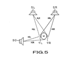
- synthetic audio signal Sb1 for left ear is obtained by passing audio signal Sao of the sound source SO through a filter which realizes the transfer function portion of the formula (1)
- synthetic audio signal Sbr for right ear is obtained by passing audio signal Sao through a filter which realizes the transfer function portion of the formula (2).
- the speaker portion is not caused to be directly attached to ear of listener in acoustic device that only listener himself uses like headphone device to add the inverse characteristic of the transfer characteristic to the ear of the listener thus to deliver an audio signal to the speaker portion, whereas the influence on the phase characteristic at crossover frequency in the multiway speaker system is not disclosed by any means.
- An object of the present invention is to provide a novel audio signal processing apparatus and a novel audio signal reproducing system which can solve or eliminate problems that prior arts as described above have.
- Another object of the present invention is to provide an audio signal processing apparatus and an audio signal reproducing system in which there is no necessity of allowing drive surfaces of respective drive units to flush with each other in the multiway speaker system to improve delay time difference or differences between speaker units, thus resultantly making it possible to improve sound image localization.
- the present invention is directed to an audio signal processing apparatus adapted for delivering an audio signal to a speaker system including at least two drive units or more which are divided or separated by frequency band, the audio signal processing apparatus comprising: filter means for processing an input audio signal on the basis of correction characteristic of impulse response of the speaker system in order to correct shift between phases of respective sound waves radiated from respective drive surfaces of the two drive units or more of the speaker system, thus to deliver, to the speaker system, an audio output signal which has been caused to undergo signal processing by the filter means.
- the filter means processes an input audio signal on the basis of correction characteristic of impulse response, e.g., inverse characteristic of impulse response of the speaker system.
- the present invention is directed to an audio signal processing apparatus adapted for delivering an audio signal to a speaker system including at least two drive units or more which are divided or separated by frequency band, the audio signal processing apparatus comprising: filter means comprised of FIR filter for processing an input audio signal on the basis of correction characteristic of impulse response of the speaker system in order to correct shift between phases of respective sound waves radiated from respective drive surfaces of the two drive units or more of the speaker system, thus to deliver, to the speaker system, an audio output signal which has been caused to undergo signal processing by the filter means comprised of FIR filter.
- the filter means comprised of FIR filter processes an input audio signal on the basis of correction characteristic of impulse response, e.g., inverse characteristic of impulse response of the speaker system.
- the present invention is directed to an audio signal processing apparatus adapted for delivering an audio signal to a speaker system at least including two drive units or more which are divided or separated by frequency band, the audio signal processing apparatus comprising: first filter means having an arbitrary transmission characteristic which has been determined by measurement or calculation in advance; and second filter means having correction characteristic of impulse response of the speaker system in order to correct shift between phases of respective sound waves radiated from respective drive surfaces of the two drive units or more of the speaker system, thus to deliver, to the speaker system, an audio output signal from the second filter means.
- the first filter means serves to add arbitrary characteristic which has been determined in advance by measurement or calculation to input audio signal
- the second filter means serves to add correction characteristic of impulse response of the speaker system to output signal of the first filter means.
- the present invention is directed to an audio signal processing apparatus adapted for delivering an audio signal to a speaker system including at least two drive units or more which are divided or separated by frequency band, the audio signal processing apparatus comprising: first filter means having frequency characteristic where group delay characteristic which has been determined in advance by measurement or calculation is constant; and second filter means having correction characteristic of impulse response of the speaker system in order to correct shift between phases of respective sound waves radiated from respective drive surfaces of the two drive units or more of the speaker system, thus to deliver, to the speaker system, an audio output signal from the second filter means.
- the first filter means serves to add, to input audio signal, frequency characteristic where group delay characteristic which has been determined by measurement or calculation in advance is constant, and the second filter means serves to add correction characteristic of impulse response of the speaker system to output signal of the first filter means.
- the present invention is directed to an audio signal processing apparatus adapted for delivering an audio signal to a speaker system including at least two drive units or more which are divided or separated by frequency band, the audio signal processing apparatus comprising: first filter means having characteristic for conducting a control such that sound image localization position in the case where an input audio signal is reproduced by plural speakers results in an arbitrary position; and second filter means having correction characteristic of impulse response of the speaker system in order to correct shift between phases of respective sound waves radiated from respective drive surfaces of the two drive units or more of the speaker system, thus to deliver, to the speaker system, an audio output signal from the second filter means.
- the first filter means serves to add, to input audio signal, characteristic for conducting a control such that sound image localization position in the case where input audio signal which has been determined in advance by measurement or calculation is reproduced by plural speakers results in an arbitrary position
- the second filter means serves to add correction characteristic of impulse response of the speaker system to output signal of the first filter mans.
- the present invention is directed to an audio signal processing apparatus for delivering an audio signal to a speaker system including at least two drive units or more which are divided or separated by frequency band
- the audio signal processing apparatus comprising: first filter means having impulse response characteristic of an arbitrary room, which has been determined in advance by measurement or calculation; and second filter means having correction characteristic of impulse response of the speaker system in order to correct shift between phases of respective sound waves radiated from respective drive surfaces of the two drive units or more of the speaker system, thus to deliver, to the speaker system, an audio output signal from the second filter means.
- the first filter means serves to add input audio signal to impulse response characteristic of an arbitrary room, which has been determined by measurement or calculation in advance, and the second filter means serves to add correction characteristic of impulse response of the speaker system to output signal of the first filter means.
- the present invention is directed to an audio signal processing apparatus for delivering an audio signal to a speaker system including at least two drive units or more which are divided or separated by frequency band
- the audio signal processing apparatus comprising: first filter means having impulse response characteristic of an electro-acoustic transducer, which has been determined in advance by measurement or calculation; and second filter means having correction characteristic of impulse response of the speaker system in order to correct shift between phases of respective sound waves radiated from respective drive surfaces of the two drive units or more of the speaker system, thus to deliver, to the speaker system, an audio output signal from the second filter means.
- the first filter means serves to add, to input audio signal, impulse response characteristic of the electro-acoustic transducer, which has been determined in advance by measurement or calculation, and the second filter means serves to add correction characteristic of impulse response of the speaker system to output signal of the first filter means.
- the audio signal reproducing system includes: a speaker system including at least two drive units or more which are divided or separated by frequency band; and a signal processing unit comprising filter means for processing an input audio signal on the basis of correction characteristic of impulse response of the speaker system in order to correct shift between phases of respective sound waves radiated from respective drive surfaces of the two drive units or more of the speaker system, whereby the signal processing unit delivers, to the speaker system, an audio output signal which has been caused to undergo signal processing by the filter means.
- Another audio signal reproducing system includes: a speaker system including at least two drive units or more which are divided or separated by frequency band; and a signal processing unit comprising first filter means having an arbitrary transmission characteristic which has been determined by measurement or calculation in advance, and second filter means having correction characteristic of impulse response of the speaker system in order to correct shift between phases of respective sound waves radiated from respective drive surfaces of the two drive units or more of the speaker system, whereby the signal processing unit delivers, to the speaker system, an audio output signal from the second filter means.
- an input audio signal is processed on the basis of correction characteristic of impulse response, e.g., inverse characteristic of impulse response of the speaker system by the filter means, propagation delay time difference does not take place at reproduction frequency bands of the speaker system so that phases of wave fronts are not shifted. For this reason, satisfactory sound image localization can be obtained.
- correction characteristic of impulse response e.g., inverse characteristic of impulse response of the speaker system by the filter means
- the first filter means serves to add, to input audio signal, arbitrary transmission characteristic which has been determined in advance by measurement or calculation
- the second filter means serves to add correction characteristic of impulse response of the speaker system to output signal of the first filter means. Accordingly, propagation delay time difference does not take place at reproduction frequency bands so that phases of wave fronts are not shifted. For this reason, satisfactory sound image localization can be obtained. Thus, it becomes possible to reproduce an arbitrary transmission characteristic to be added without deteriorating the characteristic.
- the first filter means serves to add, to an input audio signal, frequency characteristic where group delay characteristic which has been determined in advance by measurement or calculation is constant
- the second filter means serves to add correction characteristic of impulse response of the speaker system to an output signal of the first filter means. Accordingly, it becomes possible to realize, without deteriorating the characteristic, filter having an arbitrary frequency characteristic in which group delay characteristic to be added is constant.
- the first filter means serves to add, to an input audio signal, characteristic for conducting a control such that sound image localization position in the case where an input audio signal is reproduced by plural speakers results in an arbitrary position
- the second filter means serves to add correction characteristic of impulse response of the speaker system to an output signal of the first filter means. Accordingly, it becomes possible to realize, without deteriorating the characteristic, filter for conducting a control such that sound image localization position in the case where an input audio signal to be added is reproduced by plural speakers results in an arbitrary position. Thus, satisfactory sound image localization characteristic can be obtained.
- the first filter means serves to add, to an input audio signal, impulse response characteristic of an arbitrary room, which has been determined in advance by measurement or calculation
- the second filter means serves to add correction characteristic of impulse response of the speaker system to an output signal of the first filter means. Accordingly, it becomes possible to reproduce, without deteriorating the characteristic, impulse response of an arbitrary room to be added. Thus, it becomes possible to reproduce impulse response of a room equivalent to the impulse response which has been measured.
- the first filter means serves to add, to an input audio signal, impulse response characteristic of the electro-acoustic transducer, which has been determined in advance by measurement or calculation
- the second filter means serves to add correction characteristic of impulse response of the speaker system to an output signal of the first filter means. Accordingly, it becomes possible to reproduce, without deteriorating the characteristic, impulse response of the electro-acoustic transducer to be added. Thus, it becomes possible to reproduce reproduction sound equivalent to, e.g., electro-acoustic transducer which is called famous article or instrument, or has been difficult to obtain.
- the audio signal reproducing system includes signal processing unit comprising filter means for processing an input audio signal on the basis of correction characteristic of impulse response of the speaker system in order to correct shift between phases of respective sound waves radiated from respective drive surfaces of two drive units or more of the speaker system. Accordingly, propagation delay time difference does not take place at reproduction frequency bands of the speaker system so that phases of wave fronts are not shifted. For this reason, satisfactory sound image localization can be obtained.
- the audio signal reproducing system includes signal processing unit comprising first filter means having an arbitrary transmission characteristic which has been determined in advance by measurement or calculation, and second filter means having correction characteristic of impulse response of the speaker system in order to correct shift between phases of respective sound waves radiated from respective drive surfaces of two drive units or more of the speaker system. Accordingly, it becomes possible to reproduce, without deteriorating the characteristic, an arbitrary transmission characteristic to be added.
- the first embodiment is directed to an audio signal reproducing system 1 as shown in FIG. 6. While explanation will be given in the audio signal reproducing system 1 on the assumption that digital audio signal is handled as input signal, analog audio signal can be similarly handled by initially performing A/D converting processing.
- the audio signal reproducing system 1 comprises a signal processing unit (apparatus) 3 for adding characteristic which will be described later to a digital audio signal inputted from an input terminal 2, a D/A converter 4 for converting a processed output from the signal processing unit 3 into an analog signal, a power amplifier 5 for amplifying the analog signal from the D/A converter 4, and a two-way speaker system 7 composed of a unit for driving a signal at low frequency band (hereinafter simply referred to as a low frequency drive unit or driver) 9 connected to a LPF8 and a unit for driving a signal at high frequency band (hereinafter simply referred to as a high frequency drive unit or driver) 11 connected to a HPF10.
- a signal processing unit (apparatus) 3 for adding characteristic which will be described later to a digital audio signal inputted from an input terminal 2
- a D/A converter 4 for converting a processed output from the signal processing unit 3 into an analog signal
- a power amplifier 5 for amplifying the analog signal from the D/A converter 4
- the two-way speaker system 7 is directed to a speaker in which, similarly to the above-described two-way speaker system 106 shown in FIG. 1, a drive surface 9a of the low frequency drive unit 9 and a drive surface 11a of the high frequency drive unit 11 do not flush with each other, and propagation delay time difference ⁇ t between at low reproduction frequency band and at high reproduction frequency band takes place so that phase difference between sound waves takes place.
- the signal processing unit 3 serves to add, e.g., inverse characteristic, as correction characteristic of impulse response of the speaker system 7 to a digital audio signal inputted from the input terminal 2. Thereafter, the D/A converter converts the digital audio signal thus obtained back into an analog signal.
- the power amplifier 5 serves to amplify the analog signal thus obtained thereafter to deliver it to the speaker system 7.
- the speaker system 7 outputs a signal at the low frequency band that the LPF8 has passed from the drive surface 9a of the low frequency drive unit 9 as sound wave of low pitched sound, and outputs a signal at high frequency band that the HPF10 has passed from the drive surface 11a of the high frequency drive unit 11 as sound wave of high pitched sound.
- correction characteristic to be added there is used inverse characteristic of characteristic determined by measuring or calculating in advance overall impulse response of the speaker system 7 in the case where both the high frequency drive unit 11 and the low frequency drive unit 9 are driven at the same time.
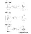
- the speaker system 7 shown in FIG. 6 has impulse response shown in FIG. 7A and frequency characteristic shown in FIG. 7B which is representation of corresponding frequency region.
- impulse response (inverse impulse response) shown in FIG. 8A can be obtained.
- FIG. 8B in this case shows amplitude frequency characteristic.
- inverse characteristic of impulse response IRI is realized by digital filter.
- impulse IP can be obtained.
- flat amplitude frequency characteristic as shown in FIG. 10B and impulse response characteristic near to impulse shown in FIG. 10A can be obtained.
- the signal processing unit 3 of the audio signal reproducing system 1 for realizing inverse characteristic of impulse response will be explained.
- the signal processing unit 3 serves to realize the inverse characteristic of the impulse response by using, e.g., digital filter 20 as shown in FIG. 11.
- a digital audio signal SD is serially delivered to plural delay circuits 22 ⁇ 22 through an input terminal 21.
- signals obtained from the terminal 21 and the delay circuits 22 ⁇ 22 are delivered to multiplier circuits 23 ⁇ 23.
- multiplication outputs are taken out to an output terminal 25 through adding circuits 24 ⁇ 24.
- the delay circuits 22 ⁇ 22 serve to give delay of one sampling period (one unit period) ⁇ to digital audio signal SD.
- the multiplier circuits 23 ⁇ 23 have inverse characteristic of the impulse response as coefficients.
- an audio signal is inputted to a system comprised of audio signal reproducing system 1 in which digital filter 20 shown in FIG. 11 is constituted by the signal processing unit 3, thereby making it possible to obtain a speaker reproducing system having satisfactory sound image localization and sound quality.
- the second embodiment is directed to an audio signal reproducing system 30 in which the system configuration is similar to that shown in FIG. 6.
- the audio signal reproducing system 30 differs from the audio signal reproducing system 1 of the first embodiment in the signal processing within the signal processing unit 31.
- signal processing at the signal processing unit 31 is performed by a filter unit 33 having an arbitrary transmission characteristic which has been determined by measurement or calculation in advance, and a filter unit 34 for realizing inverse characteristic of impulse response of the multiway speaker system.
- An arbitrary transmission characteristic that the filter unit 33 has determined by calculation is added to a digital audio signal SD inputted from the input terminal 32.
- the filter unit 34 serves to add inverse characteristic of the impulse response.
- the filter unit 33 functions as an equalizer unit to add, to the digital audio signal SD, frequency characteristic that user has arbitrarily set. Moreover, the filter unit 34 serves to add inverse characteristic of the multiway speaker system 7 which has been explained in the first embodiment to output digital audio signal of the filter unit 33.
- the equalizer function that the filter unit 33 performs will be explained.
- the filter unit 33 serves to add such a frequency characteristic that group delay characteristic is constant to the digital audio signal SD in performing equalizer processing, e.g., processing to add amplitude frequency characteristic which takes peak in the vicinity of frequency of 1 KHz as shown in FIG. 14A.
- the fact that the group delay characteristic is constant means that delay time is not changed by the frequency band so that the phase relationship is not collapsed by the frequency band.
- the filter in which the group delay characteristic is constant in the case of the FIR filter in which, e.g., the number of taps is odd, respective multiplication coefficients are symmetrical in left and right directions with the (number of taps +1)/2-th multiplier circuit being as center.
- respective multiplication coefficients are symmetrical in left and right directions.
- the FIR filter having the number of taps of 2t has group delay time corresponding to t tap.
- Such a filter in which group delay characteristic is constant can be realized by using FIR filter as shown in FIG. 11.
- the inverse characteristic of the multiway speaker system that the filter unit 34 has has been already explained.
- the inverse characteristic is added to an input signal by the FIR filter 20 shown in FIG. 1 to realize impulse response as shown in FIG. 14B. For this reason, it is possible to almost neglect the characteristic specific to the multiway speaker system.
- the audio signal reproducing system 30 of the second embodiment serves to allow the signal processing unit 31 to function (perform) processing shown in FIGS. 12 and 13 to exclude impulse response specific to the multiway speaker system in speaker output to have ability to provide an only output in which the group delay characteristic is constant.
- the signal processing unit 31 to function (perform) processing shown in FIGS. 12 and 13 to exclude impulse response specific to the multiway speaker system in speaker output to have ability to provide an only output in which the group delay characteristic is constant.
- the third embodiment is directed to an audio signal reproducing system 40 of the configuration shown in FIG. 15 in which two speakers are used to constitute virtual speaker sound source to allow sound image to undergo localization such that there results an arbitrary position.
- This system is a system in which when sound image SO is virtually reproduced by using sound source SL and sound source SR as shown in the previously mentioned FIG. 5, impulse responses specific to left and right speaker systems are excluded to obtain satisfactory sound localization characteristic.
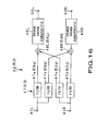
- the audio signal reproducing system 40 comprises a signal processing unit 42 for implementing processing to allow sound image by audio signal for Lch inputted from an input terminal 41L and audio signal for Rch inputted from an input terminal 41R to undergo localization such that there results an arbitrary position and for neglecting the influence of the two speaker systems, a D/A converter 43L and a D/A converter 43R which serve to convert processed output for Lch and processed output for Rch from the signal processing unit 42 into analog signals, an amplifier 44L and an amplifier 44R which serve to amplify the analog signals from the D/A converter 43L and the D/A converter 43R, and multiway speaker systems 45L and 45R for converting amplification outputs from the amplifiers 44L and 44R into sound waves.
- a signal processing unit 42 for implementing processing to allow sound image by audio signal for Lch inputted from an input terminal 41L and audio signal for Rch inputted from an input terminal 41R to undergo localization such that there results an arbitrary position and for neglecting the influence of the two speaker systems
- the signal processing unit 42 includes a filter unit 47 composed of filters 47a, 47b, 47c and 47d.
- the filter unit 47 constitutes sound image localization filter having characteristic for allowing sound image to undergo localization such that there results an arbitrary position by using two speakers by filters 47a, 47b, 47c and 47d.
- the filters 47a, 47b serve to convolutes impulse response in which transfer function similar to the transfer function portion of the above-described formulas (1) and (2) is converted into the time axis with respect to digital signal SL from the input terminal 41L.
- the filters 47c, 47d serve to convolute impulse response in which transfer function similar to the transfer function portion of the formulas (1) and (2) is converted into the time axis with respect to digital signal SR from the input terminal 41R.
- An adder 48L adds filter output of the filter 47a and filter output of the filter 47c.
- An adder 48R adds filter output of the filter 47b and filter output of the filter 47d.
- the adder 48L calculates added output corresponding to the formula described below.
- HOL ⁇ SO HLL ⁇ SL + HRL ⁇ SR
- the adder 48R calculates added output corresponding to the formula described below.
- HOR ⁇ SO HLR ⁇ SL + HRR ⁇ SR
- audio signal Sao of the sound source SO results in synthetic audio signal for left ear by passing it through the system of the adder 48L, and results in synthetic audio signal for right ear by passing it through the adder 48R.
- two speakers disposed at the positions of the sound sources SL and SR are driven, thereby making it possible to allow virtual sound source as if audio signal Sao is produced from the position of the sound source SO to undergo localization.
- synthetic audio signal for left ear is passed through a filter 49L for adding inverse characteristic of the multiway speaker system 45L
- synthetic audio signal for right ear is passed through a filter 49R for adding inverse characteristic of the multiway speaker system 45R.
- the speaker inverse characteristic is as explained in the above-described first and second embodiments. Accordingly, an output of the realized sound image localization filter is delivered to the multiway speaker systems 45L, 45R through the speaker inverse characteristic. Thus, influence of the speaker characteristic can be neglected. As a result, it becomes possible to obtain satisfactory sound image localization characteristic.
- Respective sound image localization filters may be constituted by using FIR filter as shown in FIG. 11.
- the fourth embodiment is directed to an audio signal reproducing system 51 in which the system configuration is similar to that shown in FIG. 15.
- the audio signal reproducing system 51 differs from the audio signal reproducing system 40 of the third embodiment in a portion of signal processing within the signal processing unit 52.
- the outline of the configuration of the signal processing unit 52 is similar to that of FIG. 16, but the former differs from the latter in that the filter unit 53 processes, by FIR filter, impulse response of a hall or an arbitrary room which has been determined by measurement or calculation.
- Filters 53a, 53b of the filter unit 53 reproduce transfer functions from left side sound source to left ear and right ear of listener by the impulse response of hall or arbitrary room which has been measured or calculated to convolute it with respect to digital signal.
- the filters 53c and 53d reproduce transfer functions from the right side sound source to left ear and right ear of listener by impulse response of a hall or an arbitrary room which has been measured or calculated to convolute it with respect to digital signal.
- An adder 54L adds filter output of the filter 53a and filter output of the filter 53c.
- An adder 54R adds filter output of the filter 53b and filter output of the filter 53d.
- the signal processing unit 52 can reproduce sound having sound field characteristic under different environment such as hall or arbitrary room, etc. Since sounds of reproduction multiway speaker systems 45L, 45R are further added to the above-mentioned sound in such state so that correct sound field reproduction becomes difficult, the signal processing unit 52 serves to pass added output of the adder 54L and added output of the adder 54R through filter 49L for adding inverse characteristic of the multiway speaker system 45L and filter 49R for adding inverse characteristic of the multiway speaker system 45R.
- the speaker inverse characteristic is as explained in the above-described first and second embodiments. Accordingly, realized sound field localization filter output is delivered to multiway speaker systems 45L, 45R through the speaker inverse characteristic. Thus, the influence of the speaker characteristic can be neglected. As a result, it becomes possible to obtain satisfactory sound filed characteristic near to the environment where sound filed is measured.
- the fifth embodiment is directed to an audio signal reproducing system 60 in which the system configuration is similar to that shown in FIG. 6.
- the audio signal reproducing system 60 differs from the audio signal reproducing systems 1 and 30 of the first and second embodiments in signal processing within the signal processing unit 61.
- processing at the signal processing unit 61 is performed by filter unit 33 having arbitrary transmission characteristic which has been determined in advance by measurement or calculation, and filter unit 34 for realizing inverse characteristic of impulse response of the speaker.
- the filter unit 33 functions as equalizer unit, and serves to add frequency characteristic that user arbitrarily set to digital audio signal.
- the filter unit 34 serves to add inverse characteristic of the multiway speaker system 7 which has been explained in the first embodiment to an output digital audio signal of the filter unit 33.
- impulse response of other speaker which has been determined by measurement or calculation is realized by FIR filter as shown in FIG. 11.
- Impulse response of a speaker which is called famous article or instrument is realized by FIR filter of the filter unit 33.
- an audio signal to which realized speaker impulse response has been added is delivered to multiway speaker systems 45L, 45R through filter 49L for adding the inverse characteristic of the multiway speaker system 45L and filter 49R for adding the inverse characteristic of the multiway speaker system 45R.
- the influence of the speaker characteristic can be neglected. As a result, it becomes possible to reproduce, extremely with high fidelity, other speaker characteristic which is called famous article or instrument.
- the sixth embodiment is directed to an audio signal reproducing system 70 in which the system configuration is also similar to that shown in FIG. 6.
- the audio signal reproducing system 70 also differs from the audio signal reproducing systems 1, 30 and 60 of the first, second and fifth embodiments in signal processing within the signal processing unit 71.
- processing at the signal processing unit 71 is performed by filter unit 33 having an arbitrary transmission characteristic which has been determined by measurement or calculation in advance, and filter unit 34 for realizing inverse characteristic of impulse response of the speaker.
- the filter unit 33 functions as an equalizer unit, and serves to add frequency characteristic that user has arbitrarily set to digital audio signal.
- the filter unit 34 serves to add inverse characteristic of the multiway speaker system 7 which has been explained in the above-mentioned embodiment to output digital audio signal of the filter unit 33.
- impulse response of record needle which has been determined by measurement or calculation is realized by FIR filter.
- Impulse response of record needle which is so called famous article or instrument, or record needle difficult to obtain at present is realized by FIR filter.
- an audio signal to which realized impulse response of record needle has been added is delivered to multiway speaker systems 45L, 45R through filter 49L for adding inverse characteristic of the multiway speaker system 45L and filter 49R for adding inverse characteristic of the multiway speaker system 45R.
- the influence of the speaker characteristic can be neglected. As a result, it becomes possible to reproduce, extremely with high fidelity, the primary characteristic of the record needle to hear corresponding sound.
- the seventh embodiment is directed to an audio signal reproducing system 80 in which the system configuration is similar to that shown in FIG. 6.
- the audio signal reproducing system 80 differs from the audio signal reproducing systems 1, 30, 60 and 70 of the first, second, fifth and sixth embodiment in signal processing within the signal processing unit 81.
- signal processing at the signal processing unit 81 is performed by filter unit 33 having arbitrary transmission characteristic which has been determined in advance by measurement or calculation, and filter unit 34 for realizing inverse characteristic of impulse response of the speaker.
- the filter unit 33 functions as an equalizer unit, and serves to add frequency characteristic that user has ordinarily set to digital audio signal.
- the filter unit 34 serves to add inverse characteristic of the multiway speaker system 7 which has been explained in the first embodiment to an output digital audio signal of the filter unit 33.
- impulse response of recording/reproducing device or instrument which has been determined by measurement or calculation is realized.
- the recording/reproducing device is record player, tape recorder, CD player or MD player, etc. There may be employed recording/reproducing device which is so called famous article or instrument, or recording/reproducing device difficult to obtain at present.
- the impulse response may be realized by the FIR filter of the filter unit 33.
- an audio signal to which realized impulse response of the recording/reproducing device has been added is delivered to the multiway speaker systems 45L, 45R through filter 49L for adding the inverse characteristic of the multiway speaker system 45L and filter 49R for adding the inverse characteristic of the multiway speaker system 45R.
- the influence of the speaker characteristic can be neglected. As a result, it is possible to reproduce, extremely with high fidelity, the primary characteristic of the recording/reproducing device to hear it.
- the eighth embodiment is directed to an audio signal reproducing system 90 in which the system configuration is similar to that shown in FIG. 6.
- the audio signal reproducing system 90 differs from the audio signal reproducing systems 1, 30, 60, 70 and 80 in signal processing within the signal processing unit 91.
- the signal processing performed at the signal processing unit 91 is as shown in FIG. 12. The detail thereof is similar to that of FIG. 13.
- impulse response of amplifier which has been determined by measurement or calculation is realized by FIR filter.
- FIR filter There may be employed an amplifier which is so called famous article or decvice, or amplifier difficult to obtain at present.
- Impulse response of such amplifier is realized by the FIR filter of the filter unit 33.
- an audio signal to which realized impulse response of the amplifier has been added is delivered to multiway speaker systems 45L, 45R through filter 49 for adding the inverse characteristic of the multiway speaker system 45L and filter 49R for adding the inverse characteristic of the multiway speaker system 45R.
- the influence of the speaker characteristic can be neglected. As a result, it becomes possible to reproduce, extremely with high fidelity, primary characteristic of the amplifier to hear it.
- the ninth embodiment is directed to an audio signal reproducing system in which there is employed a configuration such that impulse responses of plural electro-acoustic transducers, which have been determined by measurement or calculation, are realized by FIR filter, and coefficients of the filter for determining impulse response are permitted to be varied, thus to selectively and variably reproduce characteristics of plural electro-acoustic transducers by selection of user or rewriting coefficients.
- the electro-acoustic transducer is speaker, headphone system, record needle, recording/reproducing device, device with frequency characteristic and/or amplifier, etc.
- the audio signal reproducing system 120 comprises a signal processing unit 122 for adding the characteristic which will be described later to a digital audio signal inputted from an input terminal 121, a D/A converter 123 for converting processed output from the signal processing unit 122 into an analog signal, a power amplifier 124 for amplifying the analog signal from the D/A converter 123, and a two-way speaker system 7 composed of low frequency drive unit 9 connected to LPF8 and high frequency drive unit 11 connected to HPF10.
- the audio signal reproducing system 120 comprises a memory unit 125 serving as work area for storing characteristics of impulse responses of plural electro-acoustic transducers and for rewriting impulse response characteristics, a control unit 126 serving to conduct a control for selecting impulse response stored in the memory unit 125 and for rewriting it, and characteristic selector means 127 for selecting characteristic by the impulse response by taste of user through the control unit 126.
- signal processing at the signal processing unit 122 is performed by filter unit 33 having arbitrary transmission characteristic which has been determined in advance by measurement or calculation, and filter unit 34 for realizing the inverse characteristic of the impulse response of the speaker.
- the filter unit 33 functions as an equalizer unit, and serves to add frequency characteristic that user has arbitrarily set to digital audio signal.
- the filter unit 34 serves to add the inverse characteristic of the multiway speaker which has been explained in the above-mentioned first embodiment to an output digital audio signal of the filter unit 33.
- impulse responses of plural electro-acoustic transducers which have been determined by measurement or calculation are realized by FIR filter.
- the impulse responses of the plural electro-acoustic transducers used in this filter are permitted to be freely varied by control from the control unit 126. Since plural impulse response data are stored in memory unit 125, user selects characteristic among them in accordance with sound source or taste by characteristic selector means 127 under control of the control unit 126. Coefficients within the signal processing unit are rewritten by impulse response characteristic which has been selected from the memory unit 125 to thereby bring into the state where sound can be heard by new coefficients.
- This output is delivered to the multiway speaker system 7 through filter unit 34 for adding the inverse characteristic of the multiway speaker system 7.
- the influence of the speaker characteristic can be neglected. As a result, it becomes possible to selectively reproduce, extremely with high fidelity, primary characteristic of plural electro-acoustic transducers to hear it.
- filter arrangement which has been explained with reference to FIGS. 12, 13 and 16 may be exchanged in the above-described embodiments.
- speaker inverse characteristic filter unit 34 may be placed at the preceding stage of the filter unit 33 of FIG. 13.
- coaxial arrangement two-way speaker system as shown in the FIG. 15 may be used.
- the coaxial arrangement two-way speaker is a system in which the high frequency drive unit 104 and the low frequency drive unit 102 are coaxially disposed so that their drive axes flush with each other as described above.
- the high frequency drive unit 104 is disposed at the front face of the low frequency drive unit 102 from a structural point of view, drive surface of sound wave of the high frequency drive unit 104 and drive surface of sound wave of the low frequency drive unit 102 are shifted. As a result, propagation delay time difference At would take place. For this reason, phases of wave fronts of sound waves are necessarily shifted by reproduction frequency band. This is not preferable in order to obtain satisfactory sound image localization.
Landscapes
- Physics & Mathematics (AREA)
- Engineering & Computer Science (AREA)
- Acoustics & Sound (AREA)
- Signal Processing (AREA)
- Health & Medical Sciences (AREA)
- General Health & Medical Sciences (AREA)
- Otolaryngology (AREA)
- Stereophonic System (AREA)
- Circuit For Audible Band Transducer (AREA)
- Obtaining Desirable Characteristics In Audible-Bandwidth Transducers (AREA)
Applications Claiming Priority (2)
| Application Number | Priority Date | Filing Date | Title |
|---|---|---|---|
| JP2003417334A JP2005184040A (ja) | 2003-12-15 | 2003-12-15 | 音声信号処理装置及び音声信号再生システム |
| PCT/JP2004/018600 WO2005057984A1 (ja) | 2003-12-15 | 2004-12-13 | 音声信号処理装置及び音声信号再生システム |
Publications (2)
| Publication Number | Publication Date |
|---|---|
| EP1696703A1 true EP1696703A1 (de) | 2006-08-30 |
| EP1696703A4 EP1696703A4 (de) | 2010-06-02 |
Family
ID=34675187
Family Applications (1)
| Application Number | Title | Priority Date | Filing Date |
|---|---|---|---|
| EP04806961A Ceased EP1696703A4 (de) | 2003-12-15 | 2004-12-13 | Audiosignalverarbeitungseinrichtung und audiosignalwiedergabesystem |
Country Status (6)
| Country | Link |
|---|---|
| US (1) | US20070127738A1 (de) |
| EP (1) | EP1696703A4 (de) |
| JP (1) | JP2005184040A (de) |
| KR (1) | KR20060128872A (de) |
| CN (1) | CN100586229C (de) |
| WO (1) | WO2005057984A1 (de) |
Cited By (2)
| Publication number | Priority date | Publication date | Assignee | Title |
|---|---|---|---|---|
| CN102075827A (zh) * | 2010-12-29 | 2011-05-25 | 东莞达电电子有限公司 | 一种具有双扬声器结构的耳机 |
| CN101770769B (zh) * | 2008-12-26 | 2012-09-19 | 雅马哈株式会社 | 频带划分装置 |
Families Citing this family (37)
| Publication number | Priority date | Publication date | Assignee | Title |
|---|---|---|---|---|
| KR20060022968A (ko) * | 2004-09-08 | 2006-03-13 | 삼성전자주식회사 | 음향재생장치 및 음향재생방법 |
| FR2901448B1 (fr) * | 2006-05-19 | 2009-01-09 | Cabasse Sa | Dispositif et procede de filtrage d'un signal d'activation destine a alimenter un haut-parleur a membranes coaxiales, enceinte acoustique,programme informatique et moyen de stockage correspondants. |
| US8520873B2 (en) * | 2008-10-20 | 2013-08-27 | Jerry Mahabub | Audio spatialization and environment simulation |
| US8224009B2 (en) * | 2007-03-02 | 2012-07-17 | Bose Corporation | Audio system with synthesized positive impedance |
| EP1986466B1 (de) * | 2007-04-25 | 2018-08-08 | Harman Becker Automotive Systems GmbH | Verfahren und Vorrichtung zur Klangabstimmung |
| JP2008283600A (ja) * | 2007-05-14 | 2008-11-20 | Pioneer Electronic Corp | 自動音場補正装置 |
| WO2009008068A1 (ja) * | 2007-07-11 | 2009-01-15 | Pioneer Corporation | 自動音場補正装置 |
| JP5070993B2 (ja) * | 2007-08-27 | 2012-11-14 | 富士通株式会社 | 音処理装置、位相差補正方法及びコンピュータプログラム |
| US8401202B2 (en) * | 2008-03-07 | 2013-03-19 | Ksc Industries Incorporated | Speakers with a digital signal processor |
| JP2010021982A (ja) * | 2008-06-09 | 2010-01-28 | Mitsubishi Electric Corp | 音響再生装置 |
| WO2010013145A1 (en) * | 2008-08-01 | 2010-02-04 | Canon Kabushiki Kaisha | Speaker system with at least two codirectional channels |
| DE102008058028A1 (de) * | 2008-11-18 | 2010-05-20 | K+H Vertriebs- Und Entwicklungsgesellschaft Mbh | Lautsprechereinheit |
| JP5605071B2 (ja) * | 2010-08-10 | 2014-10-15 | 株式会社Jvcケンウッド | ディジタルフィルタの係数設定方法、係数設定装置、及び係数設定プログラム、並びにディジタルフィルタを用いた音場補正方法 |
| JP5885918B2 (ja) * | 2010-10-29 | 2016-03-16 | ソニー株式会社 | 表示装置、音声信号処理方法およびプログラム |
| US8934653B2 (en) * | 2011-01-13 | 2015-01-13 | Chris Pelonis | Rhomboid shaped acoustic speaker |
| JP6051505B2 (ja) * | 2011-10-07 | 2016-12-27 | ソニー株式会社 | 音声処理装置および音声処理方法、記録媒体、並びにプログラム |
| CN102447446A (zh) * | 2011-12-09 | 2012-05-09 | 苏州上声电子有限公司 | 基于振动元件运动状态反馈的扬声器频响均衡方法和装置 |
| KR101920029B1 (ko) | 2012-08-03 | 2018-11-19 | 삼성전자주식회사 | 모바일 장치 및 제어방법 |
| US9286863B2 (en) * | 2013-09-12 | 2016-03-15 | Nancy Diane Moon | Apparatus and method for a celeste in an electronically-orbited speaker |
| JP2016100613A (ja) | 2014-11-18 | 2016-05-30 | ソニー株式会社 | 信号処理装置、信号処理方法、およびプログラム |
| CN104378713B (zh) * | 2014-11-27 | 2017-11-07 | 广州得易电子科技有限公司 | 一种阵列扬声器及使用该扬声器的音频处理方法 |
| JP6434333B2 (ja) * | 2015-02-19 | 2018-12-05 | クラリオン株式会社 | 位相制御信号生成装置、位相制御信号生成方法及び位相制御信号生成プログラム |
| CN114694632B (zh) * | 2015-09-16 | 2025-08-19 | 株式会社东芝 | 语音处理装置 |
| JP6202076B2 (ja) * | 2015-12-07 | 2017-09-27 | オンキヨー株式会社 | 音声処理装置 |
| WO2017141292A1 (ja) | 2016-02-17 | 2017-08-24 | パナソニックIpマネジメント株式会社 | 音声再生装置 |
| US10251012B2 (en) * | 2016-06-07 | 2019-04-02 | Philip Raymond Schaefer | System and method for realistic rotation of stereo or binaural audio |
| DE102016116421B4 (de) * | 2016-07-07 | 2026-01-15 | Infineon Technologies Ag | Sensoranordnung mit optimierter gruppenlaufzeit und verfahren zur signalverarbeitung |
| US10149083B1 (en) * | 2016-07-18 | 2018-12-04 | Aspen & Associates | Center point stereo system |
| US9883304B1 (en) * | 2016-07-29 | 2018-01-30 | Sonos, Inc. | Lifetime of an audio playback device with changed signal processing settings |
| CN106231499A (zh) * | 2016-09-29 | 2016-12-14 | 宇龙计算机通信科技(深圳)有限公司 | 一种音效增强方法与装置 |
| TWI651970B (zh) * | 2017-01-25 | 2019-02-21 | 佳世達科技股份有限公司 | 分音裝置 |
| EP3579575A4 (de) * | 2017-02-02 | 2020-11-11 | Clarion Co., Ltd. | Schallvorrichtung und schallsteuerungsvorrichtung |
| JP6761773B2 (ja) * | 2017-03-28 | 2020-09-30 | Toa株式会社 | 屋外音声シミュレーションプログラム及び電子機器 |
| JP7065414B2 (ja) * | 2017-08-29 | 2022-05-12 | パナソニックIpマネジメント株式会社 | 仮想音像制御システム、照明器具、厨房装置、天井部材、及びテーブル |
| KR20220013630A (ko) | 2020-07-27 | 2022-02-04 | 삼성전자주식회사 | 오디오의 채널의 수를 변환하는 전자 장치 및 전자 장치의 동작 방법 |
| JP7466196B2 (ja) * | 2020-12-17 | 2024-04-12 | 株式会社ユニバーサルエンターテインメント | 遊技機 |
| WO2024169133A1 (zh) * | 2023-02-17 | 2024-08-22 | 深圳市倍思科技有限公司 | 空间音频处理装置、设备、方法以及头戴式耳机 |
Family Cites Families (17)
| Publication number | Priority date | Publication date | Assignee | Title |
|---|---|---|---|---|
| JP2681349B2 (ja) * | 1986-08-08 | 1997-11-26 | ヤマハ株式会社 | スピーカ再生装置 |
| US4885782A (en) * | 1987-05-29 | 1989-12-05 | Howard Krausse | Single and double symmetric loudspeaker driver configurations |
| GB2250658A (en) * | 1990-12-07 | 1992-06-10 | Canon Res Ct Europe Ltd | Loudspeaker |
| GB2252023B (en) | 1991-01-21 | 1995-01-18 | Mitsubishi Electric Corp | Acoustic system |
| KR0139176B1 (ko) * | 1992-06-30 | 1998-06-15 | 김광호 | 다해상도 선형왜곡 보상방법 및 그 장치 |
| JP2871387B2 (ja) * | 1992-07-27 | 1999-03-17 | ヤマハ株式会社 | 音像定位装置 |
| JP3148060B2 (ja) * | 1993-12-02 | 2001-03-19 | 富士通テン株式会社 | 聴取位置自動補正装置 |
| WO1995034883A1 (en) * | 1994-06-15 | 1995-12-21 | Sony Corporation | Signal processor and sound reproducing device |
| JPH0970092A (ja) * | 1995-09-01 | 1997-03-11 | Saalogic:Kk | 点音源・無指向性・スピ−カシステム |
| JPH1051890A (ja) * | 1996-07-31 | 1998-02-20 | Victor Co Of Japan Ltd | オーディオ信号伝送回路 |
| US7035417B1 (en) * | 1999-04-05 | 2006-04-25 | Packard Thomas N | System for reducing noise in the reproduction of recorded sound signals |
| DE50014983D1 (de) * | 1999-10-01 | 2008-04-03 | Martin Kling | Lautsprecherkombination |
| CN1541500A (zh) * | 2000-08-28 | 2004-10-27 | �ʼҷ����ֵ�������˾ | 声音发生系统 |
| US7119267B2 (en) * | 2001-06-15 | 2006-10-10 | Yamaha Corporation | Portable mixing recorder and method and program for controlling the same |
| JP2003230198A (ja) * | 2002-02-01 | 2003-08-15 | Matsushita Electric Ind Co Ltd | 音像定位制御装置 |
| JP3994788B2 (ja) * | 2002-04-30 | 2007-10-24 | ソニー株式会社 | 伝達特性測定装置、伝達特性測定方法、及び伝達特性測定プログラム、並びに増幅装置 |
| JP3852413B2 (ja) * | 2003-02-21 | 2006-11-29 | ヤマハ株式会社 | 指向性拡声装置 |
-
2003
- 2003-12-15 JP JP2003417334A patent/JP2005184040A/ja active Pending
-
2004
- 2004-12-13 US US10/581,096 patent/US20070127738A1/en not_active Abandoned
- 2004-12-13 CN CN200480037086A patent/CN100586229C/zh not_active Expired - Fee Related
- 2004-12-13 KR KR1020067009599A patent/KR20060128872A/ko not_active Ceased
- 2004-12-13 WO PCT/JP2004/018600 patent/WO2005057984A1/ja not_active Ceased
- 2004-12-13 EP EP04806961A patent/EP1696703A4/de not_active Ceased
Cited By (2)
| Publication number | Priority date | Publication date | Assignee | Title |
|---|---|---|---|---|
| CN101770769B (zh) * | 2008-12-26 | 2012-09-19 | 雅马哈株式会社 | 频带划分装置 |
| CN102075827A (zh) * | 2010-12-29 | 2011-05-25 | 东莞达电电子有限公司 | 一种具有双扬声器结构的耳机 |
Also Published As
| Publication number | Publication date |
|---|---|
| KR20060128872A (ko) | 2006-12-14 |
| CN1895001A (zh) | 2007-01-10 |
| US20070127738A1 (en) | 2007-06-07 |
| CN100586229C (zh) | 2010-01-27 |
| HK1095966A1 (zh) | 2007-05-18 |
| WO2005057984A1 (ja) | 2005-06-23 |
| EP1696703A4 (de) | 2010-06-02 |
| JP2005184040A (ja) | 2005-07-07 |
Similar Documents
| Publication | Publication Date | Title |
|---|---|---|
| EP1696703A1 (de) | Audiosignalverarbeitungseinrichtung und audiosignalwiedergabesystem | |
| US6385320B1 (en) | Surround signal processing apparatus and method | |
| JPS63224599A (ja) | ステレオ処理装置 | |
| JP2003230198A (ja) | 音像定位制御装置 | |
| JP4744695B2 (ja) | 仮想音源装置 | |
| KR100956265B1 (ko) | 음성재생장치 | |
| JPH07288899A (ja) | 音場再生装置 | |
| JP2910891B2 (ja) | 音響信号処理装置 | |
| JP2944424B2 (ja) | 音響再生回路 | |
| JPH0984173A (ja) | 音響再生装置 | |
| JP2723153B2 (ja) | 小音像複合スピーカシステムの使用方法 | |
| JP2003111198A (ja) | 音声信号処理方法および音声再生システム | |
| JP2985557B2 (ja) | サラウンド信号処理装置 | |
| JPH06225397A (ja) | 音場制御装置 | |
| JP2947456B2 (ja) | サラウンド信号処理装置及び映像音声再生装置 | |
| HK1095966B (en) | Audio signal processing device and audio signal reproduction system | |
| JP2945232B2 (ja) | 音像定位制御装置 | |
| JPH0795877B2 (ja) | 多次元立体音場再生装置 | |
| JPH03250900A (ja) | ヘッドホン再生装置 | |
| JPH01223895A (ja) | 音響再生装置 | |
| JP2578363Y2 (ja) | 非直線位相fir型ディジタルチャンネルデバイダ。 | |
| JP3925633B2 (ja) | 音声再生装置 | |
| JPH084799Y2 (ja) | ステレオ切換装置 | |
| JP3081358B2 (ja) | 音声信号処理装置 | |
| JP4617668B2 (ja) | 音声信号処理装置及び音声信号再生システム |
Legal Events
| Date | Code | Title | Description |
|---|---|---|---|
| PUAI | Public reference made under article 153(3) epc to a published international application that has entered the european phase |
Free format text: ORIGINAL CODE: 0009012 |
|
| 17P | Request for examination filed |
Effective date: 20060616 |
|
| AK | Designated contracting states |
Kind code of ref document: A1 Designated state(s): DE FR GB |
|
| RBV | Designated contracting states (corrected) |
Designated state(s): DE FR GB |
|
| DAX | Request for extension of the european patent (deleted) | ||
| RBV | Designated contracting states (corrected) |
Designated state(s): DE FR GB |
|
| A4 | Supplementary search report drawn up and despatched |
Effective date: 20100503 |
|
| RIC1 | Information provided on ipc code assigned before grant |
Ipc: H04R 3/04 20060101AFI20100426BHEP Ipc: H04R 1/24 20060101ALN20100426BHEP Ipc: H04S 1/00 20060101ALN20100426BHEP |
|
| 17Q | First examination report despatched |
Effective date: 20110519 |
|
| REG | Reference to a national code |
Ref country code: DE Ref legal event code: R003 |
|
| STAA | Information on the status of an ep patent application or granted ep patent |
Free format text: STATUS: THE APPLICATION HAS BEEN REFUSED |
|
| 18R | Application refused |
Effective date: 20130504 |