EP1699271B1 - Système de commande pour plusieurs appareils d'exploitation de lampes repartis dans l'espace et procédé de mise en service de ce système de commande - Google Patents
Système de commande pour plusieurs appareils d'exploitation de lampes repartis dans l'espace et procédé de mise en service de ce système de commande Download PDFInfo
- Publication number
- EP1699271B1 EP1699271B1 EP06001448A EP06001448A EP1699271B1 EP 1699271 B1 EP1699271 B1 EP 1699271B1 EP 06001448 A EP06001448 A EP 06001448A EP 06001448 A EP06001448 A EP 06001448A EP 1699271 B1 EP1699271 B1 EP 1699271B1
- Authority
- EP
- European Patent Office
- Prior art keywords
- lamp
- lamp operating
- operating device
- devices
- control system
- Prior art date
- Legal status (The legal status is an assumption and is not a legal conclusion. Google has not performed a legal analysis and makes no representation as to the accuracy of the status listed.)
- Expired - Lifetime
Links
Images
Classifications
-
- H—ELECTRICITY
- H05—ELECTRIC TECHNIQUES NOT OTHERWISE PROVIDED FOR
- H05B—ELECTRIC HEATING; ELECTRIC LIGHT SOURCES NOT OTHERWISE PROVIDED FOR; CIRCUIT ARRANGEMENTS FOR ELECTRIC LIGHT SOURCES, IN GENERAL
- H05B47/00—Circuit arrangements for operating light sources in general, i.e. where the type of light source is not relevant
- H05B47/10—Controlling the light source
- H05B47/175—Controlling the light source by remote control
-
- H—ELECTRICITY
- H05—ELECTRIC TECHNIQUES NOT OTHERWISE PROVIDED FOR
- H05B—ELECTRIC HEATING; ELECTRIC LIGHT SOURCES NOT OTHERWISE PROVIDED FOR; CIRCUIT ARRANGEMENTS FOR ELECTRIC LIGHT SOURCES, IN GENERAL
- H05B47/00—Circuit arrangements for operating light sources in general, i.e. where the type of light source is not relevant
- H05B47/10—Controlling the light source
- H05B47/175—Controlling the light source by remote control
- H05B47/198—Grouping of control procedures or address assignation to light sources
Definitions
- the present invention relates to a control system according to the preamble of claim 1, which has a plurality of distributed to be arranged and provided for operating gas discharge lamps lamp operating devices, which are in contact with a central control device. Moreover, the present invention relates to a method for starting up such a control system.
- each lamp operating device is assigned an operating address via which it can be contacted individually by the control device. It makes sense to choose the operating addresses according to the arrangement of the lamp operating devices, as in this way a logical link between position and operating address can be made and Accordingly, the control of the lamp operating devices is simplified.
- operating addresses have been proposed, which are composed of several blocks, wherein a first block indicates a space in which the lamp operating device is arranged. A second and a third block, the operating address, identify a group to which the operating device is assigned and a single number for the operating device. In this way, not only an individual control of the individual lamps but also a group-wise control is possible.
- the present invention is accordingly an object of the invention to provide a way to assign addresses in control systems for distributed lamp operating devices, which allows easy and fast address assignment, especially in non-dimmable devices.
- the present invention assumes that during start-up of the system and the assignment of the operating addresses, those lamp operating devices that are not currently identifying turn off their associated gas discharge lamp. This is the only option anyway, as long as they are non-dimmable devices. If a corresponding lamp operating device is then requested to identify itself, it must therefore switch on the lamp (s) assigned to it. Usually, such a starting process takes about 1.5 seconds, since the lamp operating devices are designed such that the of the Manufacturers of gas discharge lamps specified operating conditions with respect to the preheating, the preheating and the ignition voltage are met. In this way, however, the course of the procedure for the assignment of the operating addresses would be significantly delayed, since the successive switching on and off of the gas discharge lamps takes a lot of time.
- the present invention is still based on the idea that the operating conditions specified by the lamp manufacturers are not necessarily observed in this special and rather rare situation of address allocation, since a one-time deviation from the regular lamp start has no effect on the lamp life. Instead, it is switched on deliberately bridging the regular measures or start-up processes for starting the gas discharge lamp immediately, whereby the duration for switching on and off the lamp is significantly reduced. Overall, this makes the method for address allocation much more effective, since it takes less time.
- a control system for a plurality of distributed to be arranged and provided for operating gas discharge lamps lamp operating devices wherein the lamp operating devices are in contact with a central control device, each lamp operating device receiving means for receiving commands transmitted by the central controller, a control unit for Operation of the lamp operating device associated with the gas discharge lamp in response to received commands and a memory for storing an operating address, via which the lamp operating device is individually addressed by the central control means comprises, and wherein the control unit of the lamp operating device is further adapted to in a programming mode for awarding the Operating addresses to id by taking an identification state in which the lamp associated with the lamp operating device is turned on and, during the programming mode, during a period in which the lamp operating device is not identified, to assume a standby state.
- the lamp operating device associated lamp is switched off in the standby state, and that the control unit for Identifying the lamp operating device, the associated lamp, bypassing carried out during a regular lamp start-up processes, in particular with a reduced preheating time or even without preheating or turns on.
- a method for starting a control system for several distributed to be arranged and provided for operating gas discharge lamps lamp operating devices proposed which assigned to them operating addresses by a central control device individually responsive, wherein for assigning the operating addresses in a programming mode, each lamp operating device by assuming an identification state in which a lamp associated with the lamp operating device is turned on, and wherein the lamp operating devices that are not currently identifying in the programming mode assume a standby state.
- the lamp associated with a lamp operating device is switched off in the standby state, and that the lamp is switched on to avoid the start-up processes carried out during a regular lamp start, in particular with a reduced preheating time or without preheating.
- the lamp operating devices may be connected to the central control device via a bus line system.
- the lamp operating devices or their receiving devices are designed for wireless reception of the control commands.
- each lamp operating device initially assigned an originating address, under which the lamp operating device at the beginning of the programming mode for the assignment of the operating addresses at the central control device reports.
- This source address can be specified at the factory, but it would also be conceivable that this is a random address, which is generated at the beginning of the process for the assignment of the operating addresses by the lamp operating device.
- Non-dimmable lamp operating devices are preferably used in the control system according to the invention, since in this case the advantages that can be achieved with the method according to the invention are greatest.
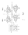
- FIG. 1 shows a designed according to the invention control system.
- the control system generally provided with the reference numeral 1 initially has a central control device 5 and a plurality of lamp operating devices 10-1 to 10-4 arranged in different rooms.
- the lamp operating devices 10-1 to 10-4 can be controlled by the central control device 5, for which purpose they are connected to the latter via a bus line system.
- This bus line system 2 may be, for example, separate control lines for transmitting commands. However, it would also be conceivable that these are at the same time also the lines of the general power supply network. In this case, the command transmission takes place by means of known powerline carrier method.
- the wireless transmission of control commands would also be conceivable, for which purpose then the individual lamp operating devices 10-1 to 10-4 would have to have correspondingly configured receiving devices.
- the control device 5 initially has as a central element a transmitting, receiving and control part 6 with a memory 7. As will be explained in detail later, within this memory 7, the original and / or operating addresses of the lamp operating devices 10-1 to 10-4 of the control system 1 are stored.
- the transmitting, receiving and control part 6 is responsible for communication with the lamp operating devices 10-1 to 10-4 and accordingly connected to the bus line system 2.
- an operating and input part 8 for example in the form of a keyboard and a display 9, are provided on the central control device 5.
- the central control device 5 could be realized by a network computer.
- the various lamp operating devices 10-1 to 10-4 are provided in particular for operating gas discharge lamps, preferably fluorescent tubes LA, and for this purpose each have a control unit 12 which is responsible for operating the gas discharge lamp LA assigned to the respective lamp operating device.
- the control unit 12 may comprise the usual components of an electronic ballast for operating gas discharge lamps.
- the control of the lamps LA should in particular be carried out in accordance with control commands which are transmitted to the respective lamp operating devices 10-1 to 10-4 from the central control device 5 via the bus line system 2.
- each lamp operating device 10-1 to 10-4 a receiving device 11, which is connected to the bus line system 2 and responsible for the communication with the central control device 5. Commands received via the bus line system 2 are then forwarded by the receiving device 11 to the control unit 12 of the corresponding lamp operating device.
- the command transmission can be carried out, for example, according to the so-called DALI (Digital Addressable Lighting Interface) standard.
- DALI Digital Addressable Lighting Interface
- ECG electronic ballasts
- the DALI standard is therefore particularly suitable for the remote-controlled dimming of lamps, but it is also possible to use non-dimmable devices. However, these can then be caused by the corresponding commands only to turn on and off the associated lamps.
- the lamp operating devices 10-1 to 10-4 also each have a memory 13, in which a corresponding operating address is stored.
- This operating address can, for example, also - as already known from the prior art - have multiple components, which in addition to an individual number also include a group number and possibly a room number. In this way, a group-wise control, for example, the lamp operating devices within a room is made possible.
- each lamp operating device 10-1 to 10-4 initially receives an originating address via which this is at least temporarily individually addressable.
- These origin addresses are stored in the respective memories 13 of the lamp operating devices 10-1 to 10-4 and can be preset, for example, at the factory.
- An alternative solution would be that the lamp operating devices 10-1 to 10-4 after a corresponding request by the central control device 5 towards each generate random addresses.
- the central control device 5 now requests all lamp operating devices 10-1 to 10-4 to send their originating addresses.
- the originating addresses received by the central control device 5 in the course of this broadcasting are then stored in the memory 7. Should there be a data collision on the lines of the bus line system 2, the central control device 5 initially stores only the faultlessly transmitted source addresses and then repeats the request to the various lamp operating devices to transmit their source addresses until all originating addresses have been received and stored without errors ,
- one of the lamp operating devices to which an operating address is to be assigned is now selected.
- the upper lamp operating device 10-3 located in the room B could first be selected.
- An operating address provided for this lamp operating device which also takes into account, for example, that the device is located in the room B, is then input to the central control device 5 by means of the keyboard 8.
- This operating address later makes it possible to selectively select the lamp operating device in the relevant room at its installation location, and indeed - if desired - also in the context of a group-wise control of the lamp operating devices.
- the central controller 5 is now caused to sequentially select the source addresses stored in the memory 7 and to prompt the associated lamp operating devices for identification.
- the identification takes place in this case in that the correspondingly addressed lamp operating devices switch on their associated gas discharge lamp LA.
- the other lamp operating devices are at this time in a standby mode in which they can indeed be addressed by the central control device 5, but the associated lamps LA are turned off.
- each lamp operating device is thus prompted to briefly switch on the gas discharge lamp LA assigned to it, it being provided according to the invention that this switching on takes place directly.
- the control units 12 are usually designed so that they start the lamps LA according to a certain scheme, in which the lamps are first preheated for a certain time and then the voltage is controlled specifically to a certain value , so that the lamp LA can ignite as gently as possible.
- Such a starting process in which the operating conditions specified by the lamp manufacturer are maintained, in particular with regard to the preheating time, the preheating current and the ignition voltage, usually takes a period of approximately 1.5 seconds. If the control system consists of a large number of lamp operating devices, it is obvious that this so-called stepping through of all the lamp operating devices, ie the successive switching on and off of the associated lamps takes a great deal of time.
- the invention provides that during the commissioning of the system, the normally carried out start-up processes for the lamp start are deliberately bypassed and in particular the lamp is turned on only with reduced preheating or even without preheating. It is deliberately accepted that the specified by the lamp manufacturer operating conditions are not met. However, since this deviation from a regular lamp start occurs extremely rarely, namely only during the commissioning of the system, this has no effect on the service life of the lamps. On the other hand, the procedure according to the invention for accelerating the operation of the system can be significantly accelerated.
- the individual lamp operating devices 10-1 to 10-4 are thus successively requested by the central control device 5 to identify themselves until the previously selected lamp operating device (here that in room B with the reference numeral 10-3) turns on its lamp LA.
- the central control device 5 If it is now recognized that the currently selected lamp operating device identifies, then this is communicated to the central control device 5, which then transmits to this active lamp operating device the previously entered desired operating address. For this purpose, the central control device 5 contacts the lamp operating device under the previously obtained source address. The link between the source address and the operating address can then be stored in the memory 7 of the central control device 5 again. The newly transmitted operating address, however, is additionally written in the corresponding memory 13 of the lamp operating device 10-3.
- the message to the central control device 5 that just identifies the desired lamp operating device could, for example, be done manually. Also, the use of an automatic detector, as in the WO 96/00459 A1 is described, would be conceivable.
- a possible variant of the method described above could be that not all origin addresses are stored in the central control device 5 at the beginning of the method. Rather, in this case, the control device 5 requests all lamp operating devices to transmit their source addresses. The first error-free received source address then becomes used to contact the appropriate lamp operating devices and request to identify themselves.
- this is the lamp operating device to which an operating address is to be assigned, this is in turn communicated to the control device 5 in a corresponding manner. If, however, another lamp operating device identifies itself, the process is repeated, with the device currently being identified being instructed not to participate in the next call, the source address.
Landscapes
- Selective Calling Equipment (AREA)
- Circuit Arrangement For Electric Light Sources In General (AREA)
Claims (18)
- Système de commande (1) pour plusieurs appareils d'alimentation de lampes (10-1, 10-2, 10-3, 10-4) à disposer de façon distribuée et prévus pour faire fonctionner des lampes à décharge de gaz (LA), lesquels appareils d'alimentation sont en contact avec un dispositif central de commande, chaque appareil d'alimentation de lampe (10-1, 10-2, 10-3, 10-4) présentant :a) un dispositif de réception (11) pour recevoir des ordres de commande transmis par le dispositif central de commande (5),b) une unité de commande (12) pour faire fonctionner la lampe à décharge de gaz (LA) attribuée à l'appareil d'alimentation de lampe (10-1, 10-2, 10-3, 10-4) en fonction d'ordre de commandes reçues etc) une mémoire (13) pour enregistrer une adresse de fonctionnement par laquelle l'appareil d'alimentation de lampe (10-1, 10-2, 10-3, 10-4) est adressable individuellement par le dispositif central de commande (5),l'unité de commande (12) de l'appareil d'alimentation de lampe (10-1, 10-2, 10-3, 10-4) étant en outre arrangé pour, dans un mode de programmation d'attribution des adresses de fonctionnement, s'identifier par la prise d'un état d'identification dans lequel la lampe (LA) attribuée à l'appareil d'alimentation de lampe (10-1, 10-2, 10-3, 10-4) est allumée, et en outre pour adopter un état de veille pendant le mode de programmation dans une période où l'appareil d'alimentation de lampe (10-1, 10-2, 10-3, 10-4) ne s'identifie pas,
caractérisé en ce que la lampe (LA) attribuée à l'appareil d'alimentation de lampe (10-1, 10-2, 10-3, 10-4) est éteinte dans l'état de veille, et
en ce que l'unité de commande (12) pour l'identification de l'appareil d'alimentation de lampe (10-1, 10-2, 10-3, 10-4) allume la lampe (LA) attribuée en évitant les processus de démarrage exécutés lors d'un démarrage de lampe régulier. - Système de commande selon la revendication 1,
caractérisé en ce que l'unité de commande (12) pour l'identification de l'appareil d'alimentation de lampe (10-1, 10-2, 10-3, 10-4) allume la lampe attribuée (LA) avec un temps de préchauffage réduit ou sans préchauffage. - Système de commande selon la revendication 1 ou 2,
caractérisé en ce que l'appareil d'alimentation de lampe (10-1, 10-2, 10-3, 10-4) est relié à l'unité centrale de commande (5) par un système de bus (2) - Système de commande selon la revendication 1 ou 2,
caractérisé en ce que le dispositif de réception (11) de l'appareil d'alimentation de lampe (10-1, 10-2, 10-3, 10-4) est arrangé pour une réception sans fil des ordres de commande. - Système de commande selon l'une des revendications précédentes,
caractérisé en ce que à chaque appareil d'alimentation de lampe (10-1, 10-2, 10-3, 10-4) est attribuée une adresse d'origine avec laquelle l'appareil d'alimentation de lampe (10-1, 10-2, 10-3, 10-4) s'annonce auprès du dispositif central de commande (5) au début du mode de programmation pour l'attribution des adresses de fonctionnement. - Système de commande selon la revendication 5,
caractérisé en ce que l'adresse d'origine est attribuée lors de la fabrication. - Système de commande selon la revendication 5,
caractérisé en que l'adresse d'origine est une adresse aléatoire générée par l'appareil d'alimentation de lampe (10-1, 10-2, 10-3, 10-4) respectif. - Système de commande selon l'une des revendications précédentes,
caractérisé en ce que les appareils d'alimentation de lampe (10-1, 10-2, 10-3, 10-4) ne sont pas variateurs d'intensité. - Appareil d'alimentation de lampe (10-1, 10-2, 10-3, 10-4) pour faire fonctionner au moins une lampe à décharge de gaz (LA), présentant :a) un dispositif de réception (11) pour recevoir des ordres de commande transmis par le dispositif central de commande (5),b) une unité de commande (12) pour faire fonctionner la lampe à décharge de gaz (LA) attribuée à l'appareil d'alimentation de lampe (10-1, 10-2, 10-3, 10-4) en fonction d'ordre de commandes reçues etc) une mémoire (13) pour enregistrer une adresse de fonctionnement par laquelle l'appareil d'alimentation de lampe (10-1, 10-2, 10-3, 10-4) est adressable individuellement par le dispositif central de commande (5),l'unité de commande (12) de l'appareil d'alimentation de lampe (10-1, 10-2, 10-3, 10-4) étant en outre arrangé pour, dans un mode de programmation d'attribution des adresses de fonctionnement, s'identifier par la prise d'un état d'identification dans lequel la lampe (LA) attribuée à l'appareil d'alimentation de lampe (10-1, 10-2, 10-3, 10-4) est allumée, et en outre pour adopter un état de veille pendant le mode de programmation dans une période où l'appareil d'alimentation de lampe (10-1, 10-2, 10-3, 10-4) ne s'identifie pas,
caractérisé en ce que la lampe (LA) attribuée à l'appareil d'alimentation de lampe (10-1, 10-2, 10-3, 10-4) est éteinte dans l'état de veille, et
en ce que l'unité de commande (12) pour l'identification de l'appareil d'alimentation de lampe (10-1, 10-2, 10-3, 10-4) allume la lampe (LA) attribuée en évitant les processus de démarrage exécutés lors d'un démarrage de lampe régulier. - Appareil d'alimentation de lampe selon la revendication 9,
caractérisé en ce que l'unité de commande (12) pour l'identification de l'appareil d'alimentation de lampe (10-1, 10-2, 10-3, 10-4) allume la lampe attribuée (LA) avec un temps de préchauffage réduit ou sans préchauffage. - Appareil d'alimentation de lampe selon la revendication 9 ou 10,
caractérisé en ce que le dispositif de réception (11) est arrangé pour une réception sans fil des ordres de commande. - Appareil d'alimentation de lampe selon l'une des revendications 9 à 11,
caractérisé en ce que à chaque appareil d'alimentation de lampe (10-1, 10-2, 10-3, 10-4) est attribuée une adresse d'origine avec laquelle l'appareil d'alimentation de lampe (10-1, 10-2, 10-3, 10-4) s'annonce auprès du dispositif central de commande (5) au début du mode de programmation pour l'attribution des adresses de fonctionnement. - Appareil d'alimentation de lampe selon la revendication 12,
caractérisé en ce que l'adresse d'origine est attribuée lors de la fabrication. - Appareil d'alimentation de lampe selon la revendication 12,
caractérisé en que l'adresse d'origine est une adresse aléatoire générée par l'appareil d'alimentation de lampe (10-1, 10-2, 10-3, 10-4). - Appareil d'alimentation de lampe selon l'une des revendications 9 à 14,
caractérisé en ce que l'appareil d'alimentation de lampe (10-1, 10-2, 10-3, 10-4) n'est pas variateur d'intensité. - Procédé de mise en service d'un système de commande (1) pour plusieurs appareils d'alimentation de lampes (10-1, 10-2, 10-3, 10-4) à disposer de façon distribuée et prévus pour faire fonctionner des lampes à décharge de gaz (LA), lesquels appareils d'alimentation sont adressables individuellement par un dispositif central de commande (5) par l'intermédiaire d'une adresse de fonctionnement qui leur est attribuée,
dans lequel, pour l'attribution des adresses de fonctionnement, chaque appareil d'alimentation de lampe (10-1, 10-2, 10-3, 10-4) s'identifie dans un mode de programmation par la prise d'un état d'identification dans lequel une lampe (LA) attribuée à l'appareil d'alimentation de lampe (10-1, 10-2, 10-3, 10-4) est allumée, et
les appareils d'alimentation de lampe (10-1, 10-2, 10-3, 10-4), qui ne s'identifient pas dans le mode de programmation, adoptent un état de veille,
caractérisé en ce que la lampe (LA) attribuée à un appareil d'alimentation de lampe (10-1, 10-2, 10-3, 10-4) est éteinte dans l'état de veille, et
en ce que, pour l'identification de l'appareil d'alimentation de lampe (10-1, 10-2, 10-3, 10-4), la lampe (LA) est allumée attribuée en évitant les processus de démarrage exécutés lors d'un démarrage de lampe régulier. - Procédé selon la revendication 16,
caractérisé en ce que, pour l'identification de l'appareil d'alimentation de lampe (10-1, 10-2, 10-3, 10-4), la lampe (LA) est allumée avec un temps de préchauffage réduit ou sans préchauffage. - Procédé selon la revendication 16 ou 17,
caractérisé en ce que l'appareil d'alimentation de lampe (10-1, 10-2, 10-3, 10-4) n'est pas variateur d'intensité.
Applications Claiming Priority (1)
| Application Number | Priority Date | Filing Date | Title |
|---|---|---|---|
| DE102005008735A DE102005008735A1 (de) | 2005-02-25 | 2005-02-25 | Steuersystem für mehrere verteilt anzuordnende Lampenbetriebsgeräte sowie Verfahren zur Inbetriebnahme eines derartigen Steuersystems |
Publications (3)
| Publication Number | Publication Date |
|---|---|
| EP1699271A2 EP1699271A2 (fr) | 2006-09-06 |
| EP1699271A3 EP1699271A3 (fr) | 2006-11-02 |
| EP1699271B1 true EP1699271B1 (fr) | 2008-07-16 |
Family
ID=36682410
Family Applications (1)
| Application Number | Title | Priority Date | Filing Date |
|---|---|---|---|
| EP06001448A Expired - Lifetime EP1699271B1 (fr) | 2005-02-25 | 2006-01-24 | Système de commande pour plusieurs appareils d'exploitation de lampes repartis dans l'espace et procédé de mise en service de ce système de commande |
Country Status (3)
| Country | Link |
|---|---|
| EP (1) | EP1699271B1 (fr) |
| AT (1) | ATE401761T1 (fr) |
| DE (2) | DE102005008735A1 (fr) |
Families Citing this family (1)
| Publication number | Priority date | Publication date | Assignee | Title |
|---|---|---|---|---|
| DE102008053487A1 (de) * | 2008-10-28 | 2010-04-29 | Osram Gesellschaft mit beschränkter Haftung | Verfahren zum Zuordnen von Orten zu Adressen von Geräten |
Family Cites Families (5)
| Publication number | Priority date | Publication date | Assignee | Title |
|---|---|---|---|---|
| DE4422215A1 (de) * | 1994-06-24 | 1996-01-04 | Zumtobel Licht | Steuersystem für mehrere verteilt anzuordnende Verbraucher, sowie Verfahren zum In-Betrieb-Setzen eines solchen Steuersystems |
| EP1002448B1 (fr) * | 1997-08-15 | 2001-11-21 | Suzo International (NL) B.V. | Systeme d'affichage presentant un certain nombre d'emetteurs lumineux et de support d'emetteurs associes |
| DE19832550B4 (de) * | 1998-07-21 | 2004-06-03 | Jens Wich | Leuchte für Notstrombeleuchtungssystem und Verfahren zur Programmierung der Leuchte |
| DE19909646A1 (de) * | 1999-03-05 | 2000-09-07 | Patent Treuhand Ges Fuer Elektrische Gluehlampen Mbh | Verfahren zur Inbetriebnahme der elektrischen Betriebsmittel eines Beleuchtungssystems |
| DE10143486A1 (de) * | 2001-09-05 | 2003-04-03 | Siemens Ag | Lichtmanagementsystem mit elektronischen Vorschaltgeräten EVG |
-
2005
- 2005-02-25 DE DE102005008735A patent/DE102005008735A1/de not_active Ceased
-
2006
- 2006-01-24 DE DE502006001090T patent/DE502006001090D1/de not_active Expired - Lifetime
- 2006-01-24 AT AT06001448T patent/ATE401761T1/de active
- 2006-01-24 EP EP06001448A patent/EP1699271B1/fr not_active Expired - Lifetime
Also Published As
| Publication number | Publication date |
|---|---|
| EP1699271A3 (fr) | 2006-11-02 |
| DE102005008735A1 (de) | 2006-08-31 |
| DE502006001090D1 (de) | 2008-08-28 |
| ATE401761T1 (de) | 2008-08-15 |
| EP1699271A2 (fr) | 2006-09-06 |
Similar Documents
| Publication | Publication Date | Title |
|---|---|---|
| EP1519634B1 (fr) | Convertisseur de données pour une installation d'éclairage et procédé de fonctionnement d'une installation d'éclairage | |
| DE4327809C2 (de) | Verfahren zum Adressieren von mit einer zentralen Steuereinheit verbundenen elektronischen Vorschaltgeräten | |
| EP0766881B1 (fr) | Systeme de commande de plusieurs consommateurs repartis dans l'espace et procede de mise en service de ce systeme de commande | |
| WO1991010276A1 (fr) | Dispositif de commande pour plusieurs consommateurs | |
| DE10344619B4 (de) | Steuersystem für mehrere verteilt angeordnete Lampenbetriebsgeräte sowie Verfahren zum Initialisieren eines derartigen Steuersystems | |
| WO2009027129A1 (fr) | Procédé pour la mise en service d'un système d'éclairage | |
| WO2006066884A1 (fr) | Procede pour programmer un equipement d'element d'eclairage | |
| WO2009121082A1 (fr) | Procédé de commande d'un appareil pour faire fonctionner un moyen d'éclairage | |
| EP1035755B1 (fr) | Méthode de mise en service des moyens de commande d'un système d'éclairage | |
| EP1955578B1 (fr) | Systeme de commande concu pour plusieurs recepteurs separes, en particulier des dispositifs fonctionnant avec des lampes, et procede de mise en marche de celui-ci | |
| DE112012001781B4 (de) | LED Beleuchtungssystem und Adressierungsverfahren für ein LED Beleuchtungssystem | |
| EP1331533B1 (fr) | Procédé d'allocation d'addresses de fonctionnement dans un système de commande avec une pluralité d'actionneurs | |
| EP1699271B1 (fr) | Système de commande pour plusieurs appareils d'exploitation de lampes repartis dans l'espace et procédé de mise en service de ce système de commande | |
| DE102012205226A1 (de) | Verfahren zum Betreiben von Geräten in einem Beleuchtungssystem | |
| EP1351366A2 (fr) | Lampe | |
| WO2016120388A1 (fr) | Procédé pour faire fonctionner des appareils dans un système d'éclairage | |
| WO2010057241A1 (fr) | Procédé d'adressage pour un moyen d'éclairage, en particulier des diodes électroluminescentes | |
| EP1624729B1 (fr) | Procédé pour la installation d'un système de illumination | |
| EP2545750B1 (fr) | Système de matériel d'éclairage à topologie de bus modulable | |
| DE102012210833A1 (de) | Verfahren zum Konfigurieren eines Beleuchtungssystems | |
| WO2007121723A1 (fr) | Système de commande de luminaires | |
| EP0821461A1 (fr) | Procédé de commande des charges électriques | |
| DE202006006633U1 (de) | Leuchtensteuerungssystem |
Legal Events
| Date | Code | Title | Description |
|---|---|---|---|
| PUAI | Public reference made under article 153(3) epc to a published international application that has entered the european phase |
Free format text: ORIGINAL CODE: 0009012 |
|
| AK | Designated contracting states |
Kind code of ref document: A2 Designated state(s): AT BE BG CH CY CZ DE DK EE ES FI FR GB GR HU IE IS IT LI LT LU LV MC NL PL PT RO SE SI SK TR |
|
| AX | Request for extension of the european patent |
Extension state: AL BA HR MK YU |
|
| PUAL | Search report despatched |
Free format text: ORIGINAL CODE: 0009013 |
|
| AK | Designated contracting states |
Kind code of ref document: A3 Designated state(s): AT BE BG CH CY CZ DE DK EE ES FI FR GB GR HU IE IS IT LI LT LU LV MC NL PL PT RO SE SI SK TR |
|
| AX | Request for extension of the european patent |
Extension state: AL BA HR MK YU |
|
| 17P | Request for examination filed |
Effective date: 20070419 |
|
| AKX | Designation fees paid |
Designated state(s): AT BE BG CH CY CZ DE DK EE ES FI FR GB GR HU IE IS IT LI LT LU LV MC NL PL PT RO SE SI SK TR |
|
| GRAP | Despatch of communication of intention to grant a patent |
Free format text: ORIGINAL CODE: EPIDOSNIGR1 |
|
| GRAS | Grant fee paid |
Free format text: ORIGINAL CODE: EPIDOSNIGR3 |
|
| GRAA | (expected) grant |
Free format text: ORIGINAL CODE: 0009210 |
|
| AK | Designated contracting states |
Kind code of ref document: B1 Designated state(s): AT BE BG CH CY CZ DE DK EE ES FI FR GB GR HU IE IS IT LI LT LU LV MC NL PL PT RO SE SI SK TR |
|
| REG | Reference to a national code |
Ref country code: GB Ref legal event code: FG4D Free format text: NOT ENGLISH |
|
| REG | Reference to a national code |
Ref country code: CH Ref legal event code: EP Ref country code: CH Ref legal event code: NV Representative=s name: BOHEST AG |
|
| REF | Corresponds to: |
Ref document number: 502006001090 Country of ref document: DE Date of ref document: 20080828 Kind code of ref document: P |
|
| REG | Reference to a national code |
Ref country code: IE Ref legal event code: FG4D Free format text: LANGUAGE OF EP DOCUMENT: GERMAN |
|
| NLV1 | Nl: lapsed or annulled due to failure to fulfill the requirements of art. 29p and 29m of the patents act | ||
| PG25 | Lapsed in a contracting state [announced via postgrant information from national office to epo] |
Ref country code: LT Free format text: LAPSE BECAUSE OF FAILURE TO SUBMIT A TRANSLATION OF THE DESCRIPTION OR TO PAY THE FEE WITHIN THE PRESCRIBED TIME-LIMIT Effective date: 20080716 Ref country code: IS Free format text: LAPSE BECAUSE OF FAILURE TO SUBMIT A TRANSLATION OF THE DESCRIPTION OR TO PAY THE FEE WITHIN THE PRESCRIBED TIME-LIMIT Effective date: 20081116 Ref country code: NL Free format text: LAPSE BECAUSE OF FAILURE TO SUBMIT A TRANSLATION OF THE DESCRIPTION OR TO PAY THE FEE WITHIN THE PRESCRIBED TIME-LIMIT Effective date: 20080716 |
|
| PG25 | Lapsed in a contracting state [announced via postgrant information from national office to epo] |
Ref country code: BG Free format text: LAPSE BECAUSE OF FAILURE TO SUBMIT A TRANSLATION OF THE DESCRIPTION OR TO PAY THE FEE WITHIN THE PRESCRIBED TIME-LIMIT Effective date: 20081016 Ref country code: SI Free format text: LAPSE BECAUSE OF FAILURE TO SUBMIT A TRANSLATION OF THE DESCRIPTION OR TO PAY THE FEE WITHIN THE PRESCRIBED TIME-LIMIT Effective date: 20080716 Ref country code: FI Free format text: LAPSE BECAUSE OF FAILURE TO SUBMIT A TRANSLATION OF THE DESCRIPTION OR TO PAY THE FEE WITHIN THE PRESCRIBED TIME-LIMIT Effective date: 20080716 Ref country code: LV Free format text: LAPSE BECAUSE OF FAILURE TO SUBMIT A TRANSLATION OF THE DESCRIPTION OR TO PAY THE FEE WITHIN THE PRESCRIBED TIME-LIMIT Effective date: 20080716 Ref country code: ES Free format text: LAPSE BECAUSE OF FAILURE TO SUBMIT A TRANSLATION OF THE DESCRIPTION OR TO PAY THE FEE WITHIN THE PRESCRIBED TIME-LIMIT Effective date: 20081027 Ref country code: PT Free format text: LAPSE BECAUSE OF FAILURE TO SUBMIT A TRANSLATION OF THE DESCRIPTION OR TO PAY THE FEE WITHIN THE PRESCRIBED TIME-LIMIT Effective date: 20081216 |
|
| REG | Reference to a national code |
Ref country code: IE Ref legal event code: FD4D |
|
| PG25 | Lapsed in a contracting state [announced via postgrant information from national office to epo] |
Ref country code: DK Free format text: LAPSE BECAUSE OF FAILURE TO SUBMIT A TRANSLATION OF THE DESCRIPTION OR TO PAY THE FEE WITHIN THE PRESCRIBED TIME-LIMIT Effective date: 20080716 Ref country code: IE Free format text: LAPSE BECAUSE OF FAILURE TO SUBMIT A TRANSLATION OF THE DESCRIPTION OR TO PAY THE FEE WITHIN THE PRESCRIBED TIME-LIMIT Effective date: 20080716 Ref country code: EE Free format text: LAPSE BECAUSE OF FAILURE TO SUBMIT A TRANSLATION OF THE DESCRIPTION OR TO PAY THE FEE WITHIN THE PRESCRIBED TIME-LIMIT Effective date: 20080716 |
|
| PLBE | No opposition filed within time limit |
Free format text: ORIGINAL CODE: 0009261 |
|
| STAA | Information on the status of an ep patent application or granted ep patent |
Free format text: STATUS: NO OPPOSITION FILED WITHIN TIME LIMIT |
|
| PG25 | Lapsed in a contracting state [announced via postgrant information from national office to epo] |
Ref country code: SK Free format text: LAPSE BECAUSE OF FAILURE TO SUBMIT A TRANSLATION OF THE DESCRIPTION OR TO PAY THE FEE WITHIN THE PRESCRIBED TIME-LIMIT Effective date: 20080716 Ref country code: RO Free format text: LAPSE BECAUSE OF FAILURE TO SUBMIT A TRANSLATION OF THE DESCRIPTION OR TO PAY THE FEE WITHIN THE PRESCRIBED TIME-LIMIT Effective date: 20080716 Ref country code: CZ Free format text: LAPSE BECAUSE OF FAILURE TO SUBMIT A TRANSLATION OF THE DESCRIPTION OR TO PAY THE FEE WITHIN THE PRESCRIBED TIME-LIMIT Effective date: 20080716 |
|
| 26N | No opposition filed |
Effective date: 20090417 |
|
| PG25 | Lapsed in a contracting state [announced via postgrant information from national office to epo] |
Ref country code: IT Free format text: LAPSE BECAUSE OF FAILURE TO SUBMIT A TRANSLATION OF THE DESCRIPTION OR TO PAY THE FEE WITHIN THE PRESCRIBED TIME-LIMIT Effective date: 20080716 Ref country code: MC Free format text: LAPSE BECAUSE OF NON-PAYMENT OF DUE FEES Effective date: 20090131 |
|
| PG25 | Lapsed in a contracting state [announced via postgrant information from national office to epo] |
Ref country code: SE Free format text: LAPSE BECAUSE OF FAILURE TO SUBMIT A TRANSLATION OF THE DESCRIPTION OR TO PAY THE FEE WITHIN THE PRESCRIBED TIME-LIMIT Effective date: 20081016 |
|
| PG25 | Lapsed in a contracting state [announced via postgrant information from national office to epo] |
Ref country code: BE Free format text: LAPSE BECAUSE OF NON-PAYMENT OF DUE FEES Effective date: 20090131 |
|
| PG25 | Lapsed in a contracting state [announced via postgrant information from national office to epo] |
Ref country code: PL Free format text: LAPSE BECAUSE OF FAILURE TO SUBMIT A TRANSLATION OF THE DESCRIPTION OR TO PAY THE FEE WITHIN THE PRESCRIBED TIME-LIMIT Effective date: 20080716 |
|
| PG25 | Lapsed in a contracting state [announced via postgrant information from national office to epo] |
Ref country code: GR Free format text: LAPSE BECAUSE OF FAILURE TO SUBMIT A TRANSLATION OF THE DESCRIPTION OR TO PAY THE FEE WITHIN THE PRESCRIBED TIME-LIMIT Effective date: 20081017 |
|
| PG25 | Lapsed in a contracting state [announced via postgrant information from national office to epo] |
Ref country code: LU Free format text: LAPSE BECAUSE OF NON-PAYMENT OF DUE FEES Effective date: 20090124 |
|
| PG25 | Lapsed in a contracting state [announced via postgrant information from national office to epo] |
Ref country code: HU Free format text: LAPSE BECAUSE OF FAILURE TO SUBMIT A TRANSLATION OF THE DESCRIPTION OR TO PAY THE FEE WITHIN THE PRESCRIBED TIME-LIMIT Effective date: 20090117 |
|
| PG25 | Lapsed in a contracting state [announced via postgrant information from national office to epo] |
Ref country code: TR Free format text: LAPSE BECAUSE OF FAILURE TO SUBMIT A TRANSLATION OF THE DESCRIPTION OR TO PAY THE FEE WITHIN THE PRESCRIBED TIME-LIMIT Effective date: 20080716 |
|
| PG25 | Lapsed in a contracting state [announced via postgrant information from national office to epo] |
Ref country code: CY Free format text: LAPSE BECAUSE OF FAILURE TO SUBMIT A TRANSLATION OF THE DESCRIPTION OR TO PAY THE FEE WITHIN THE PRESCRIBED TIME-LIMIT Effective date: 20080716 |
|
| PGFP | Annual fee paid to national office [announced via postgrant information from national office to epo] |
Ref country code: CH Payment date: 20120130 Year of fee payment: 7 |
|
| PGFP | Annual fee paid to national office [announced via postgrant information from national office to epo] |
Ref country code: AT Payment date: 20130131 Year of fee payment: 8 |
|
| REG | Reference to a national code |
Ref country code: CH Ref legal event code: PL |
|
| PG25 | Lapsed in a contracting state [announced via postgrant information from national office to epo] |
Ref country code: CH Free format text: LAPSE BECAUSE OF NON-PAYMENT OF DUE FEES Effective date: 20130131 Ref country code: LI Free format text: LAPSE BECAUSE OF NON-PAYMENT OF DUE FEES Effective date: 20130131 |
|
| REG | Reference to a national code |
Ref country code: AT Ref legal event code: MM01 Ref document number: 401761 Country of ref document: AT Kind code of ref document: T Effective date: 20140124 |
|
| PG25 | Lapsed in a contracting state [announced via postgrant information from national office to epo] |
Ref country code: AT Free format text: LAPSE BECAUSE OF NON-PAYMENT OF DUE FEES Effective date: 20140124 |
|
| REG | Reference to a national code |
Ref country code: FR Ref legal event code: PLFP Year of fee payment: 10 |
|
| PGFP | Annual fee paid to national office [announced via postgrant information from national office to epo] |
Ref country code: FR Payment date: 20150128 Year of fee payment: 10 |
|
| PGFP | Annual fee paid to national office [announced via postgrant information from national office to epo] |
Ref country code: DE Payment date: 20160331 Year of fee payment: 11 |
|
| PGFP | Annual fee paid to national office [announced via postgrant information from national office to epo] |
Ref country code: GB Payment date: 20160129 Year of fee payment: 11 |
|
| REG | Reference to a national code |
Ref country code: FR Ref legal event code: ST Effective date: 20160930 |
|
| PG25 | Lapsed in a contracting state [announced via postgrant information from national office to epo] |
Ref country code: FR Free format text: LAPSE BECAUSE OF NON-PAYMENT OF DUE FEES Effective date: 20160201 |
|
| REG | Reference to a national code |
Ref country code: DE Ref legal event code: R119 Ref document number: 502006001090 Country of ref document: DE |
|
| GBPC | Gb: european patent ceased through non-payment of renewal fee |
Effective date: 20170124 |
|
| PG25 | Lapsed in a contracting state [announced via postgrant information from national office to epo] |
Ref country code: GB Free format text: LAPSE BECAUSE OF NON-PAYMENT OF DUE FEES Effective date: 20170124 Ref country code: DE Free format text: LAPSE BECAUSE OF NON-PAYMENT OF DUE FEES Effective date: 20170801 |