EP1700663A2 - Méthode et appareil de soudage - Google Patents
Méthode et appareil de soudage Download PDFInfo
- Publication number
- EP1700663A2 EP1700663A2 EP06251228A EP06251228A EP1700663A2 EP 1700663 A2 EP1700663 A2 EP 1700663A2 EP 06251228 A EP06251228 A EP 06251228A EP 06251228 A EP06251228 A EP 06251228A EP 1700663 A2 EP1700663 A2 EP 1700663A2
- Authority
- EP
- European Patent Office
- Prior art keywords
- abnormality
- weld
- welding
- time
- repair
- Prior art date
- Legal status (The legal status is an assumption and is not a legal conclusion. Google has not performed a legal analysis and makes no representation as to the accuracy of the status listed.)
- Withdrawn
Links
Images



Classifications
-
- B—PERFORMING OPERATIONS; TRANSPORTING
- B23—MACHINE TOOLS; METAL-WORKING NOT OTHERWISE PROVIDED FOR
- B23K—SOLDERING OR UNSOLDERING; WELDING; CLADDING OR PLATING BY SOLDERING OR WELDING; CUTTING BY APPLYING HEAT LOCALLY, e.g. FLAME CUTTING; WORKING BY LASER BEAM
- B23K9/00—Arc welding or cutting
- B23K9/095—Monitoring or automatic control of welding parameters
-
- B—PERFORMING OPERATIONS; TRANSPORTING
- B23—MACHINE TOOLS; METAL-WORKING NOT OTHERWISE PROVIDED FOR
- B23K—SOLDERING OR UNSOLDERING; WELDING; CLADDING OR PLATING BY SOLDERING OR WELDING; CUTTING BY APPLYING HEAT LOCALLY, e.g. FLAME CUTTING; WORKING BY LASER BEAM
- B23K31/00—Processes relevant to this subclass, specially adapted for particular articles or purposes, but not covered by any single one of main groups B23K1/00 - B23K28/00
- B23K31/12—Processes relevant to this subclass, specially adapted for particular articles or purposes, but not covered by any single one of main groups B23K1/00 - B23K28/00 relating to investigating the properties, e.g. the weldability, of materials
- B23K31/125—Weld quality monitoring
-
- G—PHYSICS
- G05—CONTROLLING; REGULATING
- G05B—CONTROL OR REGULATING SYSTEMS IN GENERAL; FUNCTIONAL ELEMENTS OF SUCH SYSTEMS; MONITORING OR TESTING ARRANGEMENTS FOR SUCH SYSTEMS OR ELEMENTS
- G05B2219/00—Program-control systems
- G05B2219/30—Nc systems
- G05B2219/45—Nc applications
- G05B2219/45104—Lasrobot, welding robot
Definitions
- this welding equipment described in the Patent Document 1 is one which possesses means for detecting a welding current, and means for detecting a welding voltage, and in which a welding current value and a welding voltage value are detected at a weld implementation time and, in a case where the welding voltage is higher than a set voltage threshold value, there is discriminated whether the welding current exists within a set current range and, in a case where it is outside the set current range, a warning is emitted as the weld abnormality.
- a welding method of this invention is characterized in that, after a weld start signal has been inputted, a case where at least any one of a welding current and a welding voltage is outside a set range is made a weld abnormality, an abnormality generation time instant and an abnormality termination time instant are calculated with a start signal input timing being made a time axis reference, and an abnormality generation position 11 and an abnormality terminus position 12 are operated from data of the time instants and a tool tip position information of a robot, thereby detecting the weld abnormality.
- this welding method by operating the abnormality generation position from the abnormality generation time instant and operating the abnormality terminus position from the abnormality termination time instant, a weld correction is performed with the range larger than the range of this calculated weld abnormality part being made the repair welding range. For this reason, even in a case where, by an instability of a fluidity of a molten metal, the abnormality generation time instant and the abnormality generation position are different, since the weld correction is performed with the range larger than the range of the calculated weld abnormality part being made the repair welding range, it is possible to certainly repair that weld abnormality part.
- other welding method is characterized in that a welding current and a welding voltage are detected, a weld abnormality is detected on the basis of the welding current and the welding voltage, a degree of an abnormality is judged from data of the welding current and the welding voltage in a section of that abnormality, and weld repair conditions such as torch angle and aiming position are selected in compliance with the degree of the abnormality, thereby performing a weld repair by the weld repair conditions.
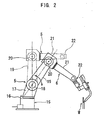
- the arm 6 of the robot 5 possesses a 1st arm 17 continuously provided in a rotation axis 16 in a main body part 15 side, a 2nd arm 19 swingably connected to the 1st arm 17 through a 1st axis 18, a 3rd arm 21 swingably connected to the 2nd arm 19 through a 2nd axis 20, and a tip tool attachment part 22 connected to the 3rd arm 21.
- FIG.2 shows a state that the welding is being performed to a weldment (work) W by using the welding equipment.
- the abnormality discrimination means 2 is one which, in a case where an input signal from the start signal input means (WCR signal input means) 4 is higher than a welding voltage threshold value and lower than a welding current threshold value after having been inputted, discriminates that range as the weld abnormality part. Further, if the weld abnormality part is discriminated by the abnormality discrimination means 2, by the time instant calculation means 3 it is possible to calculate the abnormality generation time instant and the abnormality termination time instant of the weld abnormality part with a start signal input timing being made a time axis reference.
- the operation means 8 there are being inputted the torch tip position coordinate values (X coordinate value, Y coordinate value and Z coordinate value) of the arm 6 of the robot 5 from the robot position information collection means 7.
- These position coordinate values are position coordinate values with respect to a moving (welding) time of the torch tip at the welding time. For this reason, it follows that the operation means 8 operates the abnormality generation position 11 and the abnormality terminus position 12 on the basis of the data of the abnormality generation time instant and the abnormality termination time instant of the weld abnormality part from the time instant calculation means 3, and the data of the position coordinate values from the robot position information collection means 7.
- the abnormality discrimination means 2 can make this range into one continuous abnormality section (weld abnormality part 13). Additionally, as mentioned later, in the welding equipment, since it is possible to perform a weld repair work, at a time of this weld repair work it is possible to judge a degree of the abnormality from the data of the welding current and the welding voltage of that abnormality section, thereby selecting weld repair conditions such as torch angle and aiming position in compliance with this degree of the abnormality.
- the weld goodness/badness judgment judges, in the case where the welding current and the welding voltage are higher than the welding voltage threshold value and lower than the welding current threshold value as having been mentioned above, this range as "repairneed”.
- FIG.6 there is shown one example of the weld abnormality part 13 generating in a weld line 10 formed after the welding.
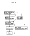
- the process shifts to a step S3, and the defective position is calculated from a defect generation time instant with the start signal input timing (WCR signal input timing) being made the time axis reference. That is, the abnormality generation time instant and the abnormality termination time instant are calculated with the start signal input timing being made the time axis reference and, from the data of these and a robot position information, the abnormality generation part 11 and the abnormality terminus position 12 are operated as shown in FIG.6. On this occasion, a defect classification is previously detected on the basis of a weld abnormality time. Next, like a step S4, a data of the above defect classification and a defective position data are sent to the robot 5.
- the weld repair of a site to be repaired is performed on the basis of these data.
- the defect classification, a defective place number, a defect start position (abnormality generation position), a defect termination position (abnormality terminus position) and the like are sent to the robot 5.
- "3" of the defect classification or the like is one denoting a defect degree in the data collection 9.
- a weld abnormality generation position/section is stored to the operation means 8. Further, in the step S16, it is judged whether or not the inter-abnormality time T2 is shorter than the B.
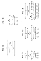
- the inter-abnormality time T2 is a time between one weld abnormality part 13 and the other weld abnormality part 13, and is a time during which there is being generated a site 14 (refer to FIG.7 that is the image diagram) in which the welding current and the welding voltage are within the set ranges.
- the B is the reference time, and is a weld minute abnormality judgment reference time (weld abnormality part interval time).
- step S16 if the inter-abnormality time T2 ⁇ the B, the process shifts to a step S17. Further if the inter-abnormality time ⁇ the B, since the interval (inter-abnormality time) between the weld abnormality parts 13 is large and the weld abnormality part 13 being generated is small, there exists a state shown in FIG.7B, so that it is judged as a sole generation of the minute abnormality and that the repair is unnecessary, thereby ending the step concerned.
- the weld repair of this range ⁇ is not performed. Further, even if the inter-abnormality time T2 is shorter than the reference time B, if the time T3 of the range ⁇ in which the weld abnormality parts 13 and the site 14 continue exceeds the 2nd set time C as shown in FIG.7D and FIG.7E, the weld repair is performed with this range ⁇ being made one continuous section.
- the range ⁇ in FIG.7D consists of the weld abnormality parts 13, 13 of one pair and the one site 14 provided between them, and is a minimum rage of a reference for judging whether or not the weld repair is necessary in a case where the weld abnormality parts 13 and the site 14 have been alternately provided in juxtaposition.
- FIG. 7E shows the range in a case where the many weld abnormality parts 13 and the many sites 14 continue.
- the range ⁇ in which the weld repair is performed or not performed consists of the weld abnormality parts 13, 13 of one pair and the one site 14 at least like FIG.7D, and the number of the weld abnormality part 13 and the site 14 becomes arbitrary.
- the weld abnormality time is calculated and the degree of the abnormality is judged from this abnormality time to thereby select the weld repair conditions such as torch angle and aiming position in compliance with this degree of the abnormality, it is possible to adapt so as to perform the weld repair under these weld repair conditions.
- a threshold value in the weld abnormality time is set and the weld abnormality time is shorter than this threshold value, it may be adapted such that it is judged to perform the weld repair work and, when the threshold value has been exceeded, it is judged that the repair cannot be performed by this weld repair work.
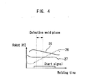
- FIG.4 a relation between the welding time and robot XYZ coordinate axes becomes as shown in FIG.4.
- a graph 25 denotes a displacement in an X axis direction
- a graph 26 denotes that in a Y axis direction
- a graph 27 denotes that in a Z axis direction.
- a defective weld place in FIG.4 is the weld abnormality part 13.
- the degree of the abnormality is judged from the weld abnormality time and it is possible to select the weld repair conditions such as torch angle and aiming position in compliance with this degree of the abnormality, it is possible to perform the repair of the weld abnormality part 13 in compliance with the degree of the abnormality, so that it is possible to contrive the improvement in productivity. Further, if the weld abnormality time T1 is longer than the 1st set time A, the length of the continuous weld abnormality part 13 is long and it follows that this range is weld-repaired.
- the weld abnormality part 13 a case where the welding current and the welding voltage are outside the set ranges is made the weld abnormality part 13
- a case where any one of the welding current and the welding voltage is outside the set range may be made the weld abnormality part 13.
- the WCR signal has been used for the start signal, there may be used other signal (e. g. , TS signal or the like) other than this WCR signal.
Landscapes
- Engineering & Computer Science (AREA)
- Mechanical Engineering (AREA)
- Physics & Mathematics (AREA)
- Plasma & Fusion (AREA)
- Quality & Reliability (AREA)
- Manipulator (AREA)
- Numerical Control (AREA)
- Arc Welding Control (AREA)
Applications Claiming Priority (1)
| Application Number | Priority Date | Filing Date | Title |
|---|---|---|---|
| JP2005063701A JP2006247663A (ja) | 2005-03-08 | 2005-03-08 | 溶接方法及び溶接装置 |
Publications (2)
| Publication Number | Publication Date |
|---|---|
| EP1700663A2 true EP1700663A2 (fr) | 2006-09-13 |
| EP1700663A3 EP1700663A3 (fr) | 2007-02-28 |
Family
ID=36603300
Family Applications (1)
| Application Number | Title | Priority Date | Filing Date |
|---|---|---|---|
| EP06251228A Withdrawn EP1700663A3 (fr) | 2005-03-08 | 2006-03-08 | Méthode et appareil de soudage |
Country Status (3)
| Country | Link |
|---|---|
| US (1) | US20060213888A1 (fr) |
| EP (1) | EP1700663A3 (fr) |
| JP (1) | JP2006247663A (fr) |
Cited By (2)
| Publication number | Priority date | Publication date | Assignee | Title |
|---|---|---|---|---|
| CN104439645A (zh) * | 2014-12-08 | 2015-03-25 | 重庆瑞阳科技开发有限公司 | 一种焊接装置和焊接方法 |
| CN115699542A (zh) * | 2020-06-08 | 2023-02-03 | 奥迪股份公司 | 对发卡式绕组的有缺陷的焊接部进行再加工的方法 |
Families Citing this family (12)
| Publication number | Priority date | Publication date | Assignee | Title |
|---|---|---|---|---|
| US20100169053A1 (en) * | 2008-12-30 | 2010-07-01 | Caterpillar Inc. | Method for creating weldment inspection documents |
| JP2010253538A (ja) * | 2009-04-28 | 2010-11-11 | Toyota Motor Corp | 溶接方法及び溶接装置 |
| JP5506294B2 (ja) * | 2009-08-28 | 2014-05-28 | 株式会社ダイヘン | アーク溶接ロボットの制御装置 |
| KR100988509B1 (ko) | 2010-06-29 | 2010-10-18 | (주) 이더 | 용접 품질 모니터링 도중 발생되는 불량 처리 장치 |
| JP2017030047A (ja) * | 2015-08-06 | 2017-02-09 | 株式会社ダイヘン | 溶着監視装置および溶接ロボットシステム |
| CN111246964A (zh) * | 2017-10-17 | 2020-06-05 | Lg电子株式会社 | 焊接系统及其操作方法 |
| CN114007792B (zh) * | 2019-06-14 | 2023-10-24 | 松下知识产权经营株式会社 | 补焊控制设备和补焊控制方法 |
| CN113993647B (zh) * | 2019-06-14 | 2024-05-28 | 松下知识产权经营株式会社 | 补焊系统 |
| WO2020262049A1 (fr) * | 2019-06-28 | 2020-12-30 | パナソニックIpマネジメント株式会社 | Dispositif de commande de soudage de réparation et procédé de commande de soudage de réparation |
| CN114080291B (zh) | 2019-06-28 | 2024-05-03 | 松下知识产权经营株式会社 | 补焊系统、补焊方法、检查装置以及机器人控制装置 |
| JP7369982B2 (ja) * | 2019-12-06 | 2023-10-27 | パナソニックIpマネジメント株式会社 | リペア溶接装置およびリペア溶接方法 |
| CN119369191A (zh) * | 2024-12-27 | 2025-01-28 | 宁波吉品科技有限公司 | 一种产品测试的修补方法及系统 |
Family Cites Families (18)
| Publication number | Priority date | Publication date | Assignee | Title |
|---|---|---|---|---|
| JPS5720659A (en) * | 1980-07-14 | 1982-02-03 | Nippon Kokan Kk <Nkk> | Detection of weld defect |
| JPS5948704B2 (ja) * | 1981-12-26 | 1984-11-28 | 岡野バルブ製造株式会社 | 原子力発電設備用y形主蒸気隔離弁用弁座自動肉盛溶設装置 |
| JPS6160272A (ja) * | 1984-08-31 | 1986-03-27 | Babcock Hitachi Kk | 溶接欠陥検出装置 |
| JPS61199578A (ja) * | 1985-02-27 | 1986-09-04 | Tokai Rika Co Ltd | ア−ク溶接ロボツトにおける溶接監視装置 |
| JP2545379B2 (ja) * | 1987-01-07 | 1996-10-16 | 株式会社日立製作所 | 溶接ロボツトの制御装置 |
| JPH01293975A (ja) * | 1988-05-18 | 1989-11-27 | Nippon Steel Corp | 溶接異常検知装置 |
| JPH0441077A (ja) * | 1990-06-08 | 1992-02-12 | Nkk Corp | 溶接モニターリングシステム |
| US5298710A (en) * | 1992-03-24 | 1994-03-29 | Bortech Corporation | Large bore welding apparatus |
| JPH0647547A (ja) * | 1992-07-28 | 1994-02-22 | Yaskawa Electric Corp | アーク溶接ロボットの制御方法及び装置 |
| JP3200825B2 (ja) * | 1993-03-17 | 2001-08-20 | 株式会社安川電機 | アーク溶接ロボットの制御方法及び装置 |
| JPH0747471A (ja) * | 1993-08-09 | 1995-02-21 | Ishikawajima Harima Heavy Ind Co Ltd | 溶接品質診断保証装置 |
| JPH07303966A (ja) * | 1994-05-11 | 1995-11-21 | Fanuc Ltd | ロボット制御装置 |
| JP3449506B2 (ja) * | 1995-03-29 | 2003-09-22 | 株式会社安川電機 | アーク溶接ロボット制御方法及び装置 |
| JP2760423B2 (ja) * | 1996-03-15 | 1998-05-28 | 株式会社日立製作所 | 溶接ロボットの制御装置 |
| JPH11285824A (ja) * | 1998-04-02 | 1999-10-19 | Ishikawajima Harima Heavy Ind Co Ltd | ステンレス薄板すみ肉tig溶接の溶接欠陥検知方法及び溶接診断機能付自動溶接装置 |
| US6130407A (en) * | 1998-07-29 | 2000-10-10 | Tregaskiss, Ltd. | Arc welding torch |
| JP4696325B2 (ja) * | 1998-12-04 | 2011-06-08 | 株式会社日立製作所 | 自動溶接及び欠陥補修方法並びに自動溶接装置 |
| JP4758019B2 (ja) * | 2001-03-30 | 2011-08-24 | 株式会社神戸製鋼所 | 溶接ロボット装置の自動運転方法 |
-
2005
- 2005-03-08 JP JP2005063701A patent/JP2006247663A/ja active Pending
-
2006
- 2006-03-08 EP EP06251228A patent/EP1700663A3/fr not_active Withdrawn
- 2006-03-08 US US11/370,183 patent/US20060213888A1/en not_active Abandoned
Cited By (5)
| Publication number | Priority date | Publication date | Assignee | Title |
|---|---|---|---|---|
| CN104439645A (zh) * | 2014-12-08 | 2015-03-25 | 重庆瑞阳科技开发有限公司 | 一种焊接装置和焊接方法 |
| CN115699542A (zh) * | 2020-06-08 | 2023-02-03 | 奥迪股份公司 | 对发卡式绕组的有缺陷的焊接部进行再加工的方法 |
| EP4162595A1 (fr) * | 2020-06-08 | 2023-04-12 | Audi Ag | Procédé de remise en état d'un joint soudé défectueux d'un enroulement en épingle à cheveux |
| CN115699542B (zh) * | 2020-06-08 | 2025-08-26 | 奥迪股份公司 | 对发卡式绕组的有缺陷的焊接部进行再加工的方法 |
| US12456906B2 (en) | 2020-06-08 | 2025-10-28 | Audi Ag | Method for reworking a faulty welded joint of a hairpin winding |
Also Published As
| Publication number | Publication date |
|---|---|
| US20060213888A1 (en) | 2006-09-28 |
| EP1700663A3 (fr) | 2007-02-28 |
| JP2006247663A (ja) | 2006-09-21 |
Similar Documents
| Publication | Publication Date | Title |
|---|---|---|
| US20060213888A1 (en) | Welding method and welding equipment | |
| CN101566546B (zh) | 电阻焊及粘合焊的在线焊缝质量检查和补焊方法 | |
| EP1618984B1 (fr) | Procédé et dispositif de soudage laser | |
| WO2020129618A1 (fr) | Système de soudage et procédé de soudage de pièce dans lequel un tel système de soudage est utilisé | |
| JP2000167666A (ja) | 自動溶接及び欠陥補修方法並びに自動溶接装置 | |
| JP7422337B2 (ja) | リペア溶接制御装置およびリペア溶接制御方法 | |
| CN111673256B (zh) | 电阻点焊焊钳电极磨损状态监测方法及监测装置 | |
| EP3698911A1 (fr) | Système de soudage et son procédé de fonctionnement | |
| KR101690991B1 (ko) | 비접촉식 온도센서를 이용한 용접용량 제어 모니터링 시스템 | |
| Barborak et al. | " Through-arc" process monitoring: techniques for control of automated gas metal arc welding | |
| CN102343475A (zh) | 用于监测和维护电阻焊接装置的方法 | |
| JP7257209B2 (ja) | 溶接チップの異常特定装置及び溶接チップの異常特定方法 | |
| KR101584421B1 (ko) | 아크 용접 모니터링 시스템 | |
| JP5358235B2 (ja) | コンデンサ放電型スタッド溶接機の溶接良否判定方法及び判定装置 | |
| CN114364480A (zh) | 焊接机以及具备其的焊接系统 | |
| CN119124010A (zh) | 异种金属接合接头的检查方法、异种金属接合接头的检查装置、焊接方法以及焊接系统 | |
| JP3396602B2 (ja) | 溶接品質監視方法および装置 | |
| KR102167563B1 (ko) | 아크 용접의 표시 장치 및 표시 방법 | |
| JP3906561B2 (ja) | 溶接品質判定方法及び装置 | |
| JP7849208B2 (ja) | 異常判定方法、異常時の処理方法、情報処理装置、溶接システム、およびプログラム | |
| US11733681B2 (en) | Spot welding system | |
| JP3906559B2 (ja) | 溶接品質判定方法及び装置 | |
| US12214437B2 (en) | Spot welding system | |
| JPS6376762A (ja) | 自動溶接方法 | |
| JPH08267244A (ja) | アーク溶接ロボット制御方法及び装置 |
Legal Events
| Date | Code | Title | Description |
|---|---|---|---|
| PUAI | Public reference made under article 153(3) epc to a published international application that has entered the european phase |
Free format text: ORIGINAL CODE: 0009012 |
|
| AK | Designated contracting states |
Kind code of ref document: A2 Designated state(s): AT BE BG CH CY CZ DE DK EE ES FI FR GB GR HU IE IS IT LI LT LU LV MC NL PL PT RO SE SI SK TR |
|
| AX | Request for extension of the european patent |
Extension state: AL BA HR MK YU |
|
| PUAL | Search report despatched |
Free format text: ORIGINAL CODE: 0009013 |
|
| AK | Designated contracting states |
Kind code of ref document: A3 Designated state(s): AT BE BG CH CY CZ DE DK EE ES FI FR GB GR HU IE IS IT LI LT LU LV MC NL PL PT RO SE SI SK TR |
|
| AX | Request for extension of the european patent |
Extension state: AL BA HR MK YU |
|
| RIC1 | Information provided on ipc code assigned before grant |
Ipc: B23P 6/04 20060101ALI20070124BHEP Ipc: B23K 31/12 20060101ALI20070124BHEP Ipc: G05B 19/18 20060101ALI20070124BHEP Ipc: B23K 9/095 20060101AFI20060717BHEP |
|
| 17P | Request for examination filed |
Effective date: 20070608 |
|
| 17Q | First examination report despatched |
Effective date: 20070713 |
|
| AKX | Designation fees paid |
Designated state(s): AT BE BG CH CY CZ DE DK EE ES FI FR GB GR HU IE IS IT LI LT LU LV MC NL PL PT RO SE SI SK TR |
|
| STAA | Information on the status of an ep patent application or granted ep patent |
Free format text: STATUS: THE APPLICATION IS DEEMED TO BE WITHDRAWN |
|
| 18D | Application deemed to be withdrawn |
Effective date: 20131001 |