EP1701009A1 - Motocyclette - Google Patents
Motocyclette Download PDFInfo
- Publication number
- EP1701009A1 EP1701009A1 EP06004991A EP06004991A EP1701009A1 EP 1701009 A1 EP1701009 A1 EP 1701009A1 EP 06004991 A EP06004991 A EP 06004991A EP 06004991 A EP06004991 A EP 06004991A EP 1701009 A1 EP1701009 A1 EP 1701009A1
- Authority
- EP
- European Patent Office
- Prior art keywords
- muffler
- disposed
- expansion chamber
- motorcycle according
- motorcycle
- Prior art date
- Legal status (The legal status is an assumption and is not a legal conclusion. Google has not performed a legal analysis and makes no representation as to the accuracy of the status listed.)
- Granted
Links
Images











Classifications
-
- F—MECHANICAL ENGINEERING; LIGHTING; HEATING; WEAPONS; BLASTING
- F01—MACHINES OR ENGINES IN GENERAL; ENGINE PLANTS IN GENERAL; STEAM ENGINES
- F01N—GAS-FLOW SILENCERS OR EXHAUST APPARATUS FOR MACHINES OR ENGINES IN GENERAL; GAS-FLOW SILENCERS OR EXHAUST APPARATUS FOR INTERNAL-COMBUSTION ENGINES
- F01N13/00—Exhaust or silencing apparatus characterised by constructional features
- F01N13/08—Other arrangements or adaptations of exhaust conduits
-
- B—PERFORMING OPERATIONS; TRANSPORTING
- B62—LAND VEHICLES FOR TRAVELLING OTHERWISE THAN ON RAILS
- B62K—CYCLES; CYCLE FRAMES; CYCLE STEERING DEVICES; RIDER-OPERATED TERMINAL CONTROLS SPECIALLY ADAPTED FOR CYCLES; CYCLE AXLE SUSPENSIONS; CYCLE SIDECARS, FORECARS, OR THE LIKE
- B62K19/00—Cycle frames
- B62K19/30—Frame parts shaped to receive other cycle parts or accessories
-
- F—MECHANICAL ENGINEERING; LIGHTING; HEATING; WEAPONS; BLASTING
- F01—MACHINES OR ENGINES IN GENERAL; ENGINE PLANTS IN GENERAL; STEAM ENGINES
- F01N—GAS-FLOW SILENCERS OR EXHAUST APPARATUS FOR MACHINES OR ENGINES IN GENERAL; GAS-FLOW SILENCERS OR EXHAUST APPARATUS FOR INTERNAL-COMBUSTION ENGINES
- F01N1/00—Silencing apparatus characterised by method of silencing
- F01N1/08—Silencing apparatus characterised by method of silencing by reducing exhaust energy by throttling or whirling
- F01N1/084—Silencing apparatus characterised by method of silencing by reducing exhaust energy by throttling or whirling the exhaust gases flowing through the silencer two or more times longitudinally in opposite directions, e.g. using parallel or concentric tubes
-
- F—MECHANICAL ENGINEERING; LIGHTING; HEATING; WEAPONS; BLASTING
- F01—MACHINES OR ENGINES IN GENERAL; ENGINE PLANTS IN GENERAL; STEAM ENGINES
- F01N—GAS-FLOW SILENCERS OR EXHAUST APPARATUS FOR MACHINES OR ENGINES IN GENERAL; GAS-FLOW SILENCERS OR EXHAUST APPARATUS FOR INTERNAL-COMBUSTION ENGINES
- F01N1/00—Silencing apparatus characterised by method of silencing
- F01N1/08—Silencing apparatus characterised by method of silencing by reducing exhaust energy by throttling or whirling
- F01N1/10—Silencing apparatus characterised by method of silencing by reducing exhaust energy by throttling or whirling in combination with sound-absorbing materials
-
- F—MECHANICAL ENGINEERING; LIGHTING; HEATING; WEAPONS; BLASTING
- F01—MACHINES OR ENGINES IN GENERAL; ENGINE PLANTS IN GENERAL; STEAM ENGINES
- F01N—GAS-FLOW SILENCERS OR EXHAUST APPARATUS FOR MACHINES OR ENGINES IN GENERAL; GAS-FLOW SILENCERS OR EXHAUST APPARATUS FOR INTERNAL-COMBUSTION ENGINES
- F01N1/00—Silencing apparatus characterised by method of silencing
- F01N1/16—Silencing apparatus characterised by method of silencing by using movable parts
- F01N1/165—Silencing apparatus characterised by method of silencing by using movable parts for adjusting flow area
-
- F—MECHANICAL ENGINEERING; LIGHTING; HEATING; WEAPONS; BLASTING
- F01—MACHINES OR ENGINES IN GENERAL; ENGINE PLANTS IN GENERAL; STEAM ENGINES
- F01N—GAS-FLOW SILENCERS OR EXHAUST APPARATUS FOR MACHINES OR ENGINES IN GENERAL; GAS-FLOW SILENCERS OR EXHAUST APPARATUS FOR INTERNAL-COMBUSTION ENGINES
- F01N1/00—Silencing apparatus characterised by method of silencing
- F01N1/24—Silencing apparatus characterised by method of silencing by using sound-absorbing materials
-
- F—MECHANICAL ENGINEERING; LIGHTING; HEATING; WEAPONS; BLASTING
- F01—MACHINES OR ENGINES IN GENERAL; ENGINE PLANTS IN GENERAL; STEAM ENGINES
- F01N—GAS-FLOW SILENCERS OR EXHAUST APPARATUS FOR MACHINES OR ENGINES IN GENERAL; GAS-FLOW SILENCERS OR EXHAUST APPARATUS FOR INTERNAL-COMBUSTION ENGINES
- F01N13/00—Exhaust or silencing apparatus characterised by constructional features
- F01N13/011—Exhaust or silencing apparatus characterised by constructional features having two or more purifying devices arranged in parallel
-
- F—MECHANICAL ENGINEERING; LIGHTING; HEATING; WEAPONS; BLASTING
- F01—MACHINES OR ENGINES IN GENERAL; ENGINE PLANTS IN GENERAL; STEAM ENGINES
- F01N—GAS-FLOW SILENCERS OR EXHAUST APPARATUS FOR MACHINES OR ENGINES IN GENERAL; GAS-FLOW SILENCERS OR EXHAUST APPARATUS FOR INTERNAL-COMBUSTION ENGINES
- F01N13/00—Exhaust or silencing apparatus characterised by constructional features
- F01N13/02—Exhaust or silencing apparatus characterised by constructional features having two or more separate silencers in series
-
- F—MECHANICAL ENGINEERING; LIGHTING; HEATING; WEAPONS; BLASTING
- F01—MACHINES OR ENGINES IN GENERAL; ENGINE PLANTS IN GENERAL; STEAM ENGINES
- F01N—GAS-FLOW SILENCERS OR EXHAUST APPARATUS FOR MACHINES OR ENGINES IN GENERAL; GAS-FLOW SILENCERS OR EXHAUST APPARATUS FOR INTERNAL-COMBUSTION ENGINES
- F01N13/00—Exhaust or silencing apparatus characterised by constructional features
- F01N13/08—Other arrangements or adaptations of exhaust conduits
- F01N13/082—Other arrangements or adaptations of exhaust conduits of tailpipe, e.g. with means for mixing air with exhaust for exhaust cooling, dilution or evacuation
-
- F—MECHANICAL ENGINEERING; LIGHTING; HEATING; WEAPONS; BLASTING
- F01—MACHINES OR ENGINES IN GENERAL; ENGINE PLANTS IN GENERAL; STEAM ENGINES
- F01N—GAS-FLOW SILENCERS OR EXHAUST APPARATUS FOR MACHINES OR ENGINES IN GENERAL; GAS-FLOW SILENCERS OR EXHAUST APPARATUS FOR INTERNAL-COMBUSTION ENGINES
- F01N13/00—Exhaust or silencing apparatus characterised by constructional features
- F01N13/18—Construction facilitating manufacture, assembly, or disassembly
- F01N13/1805—Fixing exhaust manifolds, exhaust pipes or pipe sections to each other, to engine or to vehicle body
-
- F—MECHANICAL ENGINEERING; LIGHTING; HEATING; WEAPONS; BLASTING
- F01—MACHINES OR ENGINES IN GENERAL; ENGINE PLANTS IN GENERAL; STEAM ENGINES
- F01N—GAS-FLOW SILENCERS OR EXHAUST APPARATUS FOR MACHINES OR ENGINES IN GENERAL; GAS-FLOW SILENCERS OR EXHAUST APPARATUS FOR INTERNAL-COMBUSTION ENGINES
- F01N13/00—Exhaust or silencing apparatus characterised by constructional features
- F01N13/18—Construction facilitating manufacture, assembly, or disassembly
- F01N13/1805—Fixing exhaust manifolds, exhaust pipes or pipe sections to each other, to engine or to vehicle body
- F01N13/1811—Fixing exhaust manifolds, exhaust pipes or pipe sections to each other, to engine or to vehicle body with means permitting relative movement, e.g. compensation of thermal expansion or vibration
- F01N13/1822—Fixing exhaust manifolds, exhaust pipes or pipe sections to each other, to engine or to vehicle body with means permitting relative movement, e.g. compensation of thermal expansion or vibration for fixing exhaust pipes or devices to vehicle body
-
- F—MECHANICAL ENGINEERING; LIGHTING; HEATING; WEAPONS; BLASTING
- F01—MACHINES OR ENGINES IN GENERAL; ENGINE PLANTS IN GENERAL; STEAM ENGINES
- F01N—GAS-FLOW SILENCERS OR EXHAUST APPARATUS FOR MACHINES OR ENGINES IN GENERAL; GAS-FLOW SILENCERS OR EXHAUST APPARATUS FOR INTERNAL-COMBUSTION ENGINES
- F01N3/00—Exhaust or silencing apparatus having means for purifying, rendering innocuous, or otherwise treating exhaust
- F01N3/08—Exhaust or silencing apparatus having means for purifying, rendering innocuous, or otherwise treating exhaust for rendering innocuous
- F01N3/10—Exhaust or silencing apparatus having means for purifying, rendering innocuous, or otherwise treating exhaust for rendering innocuous by thermal or catalytic conversion of noxious components of exhaust
- F01N3/24—Exhaust or silencing apparatus having means for purifying, rendering innocuous, or otherwise treating exhaust for rendering innocuous by thermal or catalytic conversion of noxious components of exhaust characterised by constructional aspects of converting apparatus
- F01N3/28—Construction of catalytic reactors
-
- B—PERFORMING OPERATIONS; TRANSPORTING
- B60—VEHICLES IN GENERAL
- B60Y—INDEXING SCHEME RELATING TO ASPECTS CROSS-CUTTING VEHICLE TECHNOLOGY
- B60Y2200/00—Type of vehicle
- B60Y2200/10—Road Vehicles
- B60Y2200/12—Motorcycles, Trikes; Quads; Scooters
-
- F—MECHANICAL ENGINEERING; LIGHTING; HEATING; WEAPONS; BLASTING
- F01—MACHINES OR ENGINES IN GENERAL; ENGINE PLANTS IN GENERAL; STEAM ENGINES
- F01N—GAS-FLOW SILENCERS OR EXHAUST APPARATUS FOR MACHINES OR ENGINES IN GENERAL; GAS-FLOW SILENCERS OR EXHAUST APPARATUS FOR INTERNAL-COMBUSTION ENGINES
- F01N2230/00—Combination of silencers and other devices
- F01N2230/04—Catalytic converters
-
- F—MECHANICAL ENGINEERING; LIGHTING; HEATING; WEAPONS; BLASTING
- F01—MACHINES OR ENGINES IN GENERAL; ENGINE PLANTS IN GENERAL; STEAM ENGINES
- F01N—GAS-FLOW SILENCERS OR EXHAUST APPARATUS FOR MACHINES OR ENGINES IN GENERAL; GAS-FLOW SILENCERS OR EXHAUST APPARATUS FOR INTERNAL-COMBUSTION ENGINES
- F01N2340/00—Dimensional characteristics of the exhaust system, e.g. length, diameter or volume of the exhaust apparatus; Spatial arrangements of exhaust apparatuses
- F01N2340/04—Arrangement of the exhaust system relative to a vehicle or parts thereof
-
- F—MECHANICAL ENGINEERING; LIGHTING; HEATING; WEAPONS; BLASTING
- F01—MACHINES OR ENGINES IN GENERAL; ENGINE PLANTS IN GENERAL; STEAM ENGINES
- F01N—GAS-FLOW SILENCERS OR EXHAUST APPARATUS FOR MACHINES OR ENGINES IN GENERAL; GAS-FLOW SILENCERS OR EXHAUST APPARATUS FOR INTERNAL-COMBUSTION ENGINES
- F01N2470/00—Structure or shape of exhaust gas passages, pipes or tubes
- F01N2470/18—Structure or shape of exhaust gas passages, pipes or tubes the axis of inlet or outlet tubes being other than the longitudinal axis of apparatus
-
- F—MECHANICAL ENGINEERING; LIGHTING; HEATING; WEAPONS; BLASTING
- F01—MACHINES OR ENGINES IN GENERAL; ENGINE PLANTS IN GENERAL; STEAM ENGINES
- F01N—GAS-FLOW SILENCERS OR EXHAUST APPARATUS FOR MACHINES OR ENGINES IN GENERAL; GAS-FLOW SILENCERS OR EXHAUST APPARATUS FOR INTERNAL-COMBUSTION ENGINES
- F01N2490/00—Structure, disposition or shape of gas-chambers
- F01N2490/14—Dead or resonance chambers connected to gas flow tube by relatively short side-tubes
-
- F—MECHANICAL ENGINEERING; LIGHTING; HEATING; WEAPONS; BLASTING
- F01—MACHINES OR ENGINES IN GENERAL; ENGINE PLANTS IN GENERAL; STEAM ENGINES
- F01N—GAS-FLOW SILENCERS OR EXHAUST APPARATUS FOR MACHINES OR ENGINES IN GENERAL; GAS-FLOW SILENCERS OR EXHAUST APPARATUS FOR INTERNAL-COMBUSTION ENGINES
- F01N2490/00—Structure, disposition or shape of gas-chambers
- F01N2490/15—Plurality of resonance or dead chambers
- F01N2490/155—Plurality of resonance or dead chambers being disposed one after the other in flow direction
-
- F—MECHANICAL ENGINEERING; LIGHTING; HEATING; WEAPONS; BLASTING
- F01—MACHINES OR ENGINES IN GENERAL; ENGINE PLANTS IN GENERAL; STEAM ENGINES
- F01N—GAS-FLOW SILENCERS OR EXHAUST APPARATUS FOR MACHINES OR ENGINES IN GENERAL; GAS-FLOW SILENCERS OR EXHAUST APPARATUS FOR INTERNAL-COMBUSTION ENGINES
- F01N2590/00—Exhaust or silencing apparatus adapted to particular use, e.g. for military applications, airplanes, submarines
- F01N2590/04—Exhaust or silencing apparatus adapted to particular use, e.g. for military applications, airplanes, submarines for motorcycles
-
- Y—GENERAL TAGGING OF NEW TECHNOLOGICAL DEVELOPMENTS; GENERAL TAGGING OF CROSS-SECTIONAL TECHNOLOGIES SPANNING OVER SEVERAL SECTIONS OF THE IPC; TECHNICAL SUBJECTS COVERED BY FORMER USPC CROSS-REFERENCE ART COLLECTIONS [XRACs] AND DIGESTS
- Y02—TECHNOLOGIES OR APPLICATIONS FOR MITIGATION OR ADAPTATION AGAINST CLIMATE CHANGE
- Y02A—TECHNOLOGIES FOR ADAPTATION TO CLIMATE CHANGE
- Y02A50/00—TECHNOLOGIES FOR ADAPTATION TO CLIMATE CHANGE in human health protection, e.g. against extreme weather
- Y02A50/20—Air quality improvement or preservation, e.g. vehicle emission control or emission reduction by using catalytic converters
Definitions
- the present invention relates to a motorcycle, and in particular to an exhaust system of a motorcycle, which includes an exhaust pipe unit connected with an engine and a muffler unit connected with the exhaust pipe unit.
- a muffler as a heavy component is disposed below an engine so that the center of gravity of the vehicle can be located at a position as low as possible.
- JP-A-2002-303133 such a construction is adopted that exhaust pipes of some cylinders extend through the side of the muffler disposed below the engine to the vicinity of a rear wheel to connect with the muffler from the rear, and exhaust pipes of the rest of the cylinders extend above the muffler to connect with extensions of some of the exhaust pipes.
- the conventional exhaust system described above adopts such a construction that the exhaust pipes coming from some of the cylinders pass through the side of the muffler.
- the length in the vehicle width direction required for disposition of the muffler and the exhaust pipes increases, and the angle of bank accordingly decreases.
- the present invention is made in view of the above fact, and an object thereof is to provide a motorcycle, and in particular an exhaust system of a motorcycle for solving the above problems, which is capable of securing an angle of bank and the center of gravity of the vehicle body located at a low position while securing a sufficient length of an exhaust pipe unit.
- a motorcycle comprising an engine, an exhaust pipe unit connected with the engine, and a muffler unit connected with the exhaust pipe unit, wherein the muffler unit includes first and second separately disposed mufflers, wherein the first muffler is connected with the exhaust pipe unit and is disposed between a lower portion of the engine and a rear wheel, and wherein the second muffler is connected with the first muffler and is disposed near a side of the rear wheel.
- the exhaust pipe unit is disposed so as to pass through the lower portion of the engine.
- inclined portions are formed on left and right sides of the first muffler such that an inclination of the inclined portions rises toward an outside in a vehicle width direction as viewed from a front of the motorcycle.
- the second muffler may extend to a rear of the vehicle and may be inclined at an angle approximately equal to that of the inclined portions of the first muffler.
- the first muffler is disposed between an oil pan of the engine and the rear wheel as viewed from the side of the motorcycle.
- a bottom surface of the first muffler is disposed approximately at the same level as that of the minimum road clearance as viewed from the side of the motorcycle.
- the second muffler extends diagonally upward to the rear with inclination, which rises toward the rear, and wherein at least a discharge port of the second muffler lies within a projection plane of the rear wheel in the vehicle width direction as viewed from the side of the motorcycle.
- an upper end plane of the discharge port of the second muffler may be disposed approximately at the same level as that of the upper end plane of a rear arm which supports the rear wheel as viewed from the side of the motorcycle.
- the first muffler is divided into a first expansion chamber formed at the rear, a second expansion chamber formed at the front, and wherein the exhaust pipe unit penetrates through the second expansion chamber and opens within the first expansion chamber; and the first and second expansion chambers are communicated with each other through a communicating pipe.
- an upstream port of a connecting passage which communicates with the second expansion chamber may be connected with the side wall of the first muffler, and a downstream port of the connecting passage may be connected with the front wall of the second muffler so as to communicate therewith.
- a first catalyst may be provided within the exhaust pipe unit in the vicinity of an upstream portion of the first muffler, and a second catalyst may be provided within the communicating pipe for connecting the first and second expansion chamber such that these chambers can communicate with each other.
- the portion of the exhaust pipe unit in which the first catalyst is provided may lie inside the angle of bank as viewed from the front of the motorcycle.
- a detection section of an oxygen sensor is inserted into the first expansion chamber of the first muffler.
- the oxygen sensor may be so positioned as to be directed to the inside front of a foot rest.
- the first muffler is disposed below the engine and attached to a vehicle body frame
- the second muffler is disposed near the side of the rear wheel
- a portion of the side wall of the first muffler near the second muffler and the front wall of the second muffler is connected through a connecting passage such that the first and second mufflers can communicate with each other.
- the first muffler includes a first expansion chamber formed at the rear, a second expansion chamber formed at the front and connected with the exhaust pipe unit, a first connecting pipe for connecting the exhaust pipe unit and the first expansion chamber passing through the second expansion chamber, and a second connecting pipe for connecting the first expansion chamber and the second expansion chamber, and the second muffler includes a third expansion chamber connected with the second expansion chamber.
- the first connecting pipe may be disposed in a lower region of the first muffler
- the second connecting pipe may be disposed in an upper region of the first muffler.
- a transverse cross section of the second connecting pipe may have a long-hole shape which is long in the vehicle width direction.
- the exhaust pipe unit has a plurality of exhaust pipes, and at least two junction pipes for unifying the respective exhaust pipes, and the respective junction pipes are connected with the first muffler and arranged in parallel in the vehicle width direction.
- a catalyst is provided within the exhaust pipe unit at a portion upstream of a connecting portion between the exhaust pipe unit and the first muffler.
- a rear suspension for connecting a rear arm for supporting the rear wheel and the vehicle body frame is disposed above the first muffler.
- the second muffler is disposed along a rear arm for supporting the rear wheel, and a clearance concave for providing a predetermined clearance between the rear arm and the outer periphery of the second muffler is formed on the rear arm.
- the lower portion of the first muffler may be covered by an under cowling, and a front opening through which flow of air generated during running of the motorcycle is introduced and a discharge opening through which the air is discharged may be formed on the under cowling.
- a connecting passage for connecting the first muffler and second muffler may be equipped with an exhaust valve for varying the passage area is disposed within the connecting passage.
- a connecting passage for connecting the first muffler and second muffler may be equipped with a heat insulating cover for covering at least the outside-vehicle portion of the connecting passage which is provided on the second muffler.
- the exhaust valve for varying the passage area may be disposed within the connecting passage, and the heat insulating cover may cover the exhaust valve as well as the connecting passage.
- Figs. 1 through 12 are figures for explaining an exhaust system of a motorcycle in a first embodiment.
- the front-to-rear and right-to-left directions in this embodiment refer to the front-to-rear and right-to-left directions as viewed from a rider sitting on a seat.
- the numeral 1 indicates a motorcycle, and the motorcycle 1 generally includes the following components.
- a front fork 4 is supported by a head pipe 3 such that the front fork 4 can be steered to the left and right.
- the head pipe 3 is attached to the front end of a vehicle body frame 2 made of aluminum alloy.
- a front wheel 5 and steering handlebars 6 are disposed at the lower end and the upper end of the front fork 4, respectively.
- a rear arm 7 is supported by left and right rear brackets 2b of the vehicle body frame 2 such that the rear arm 7 can swing upward and downward.
- a rear wheel 8 is disposed at the rear end of the rear arm 7.
- the vehicle body frame 2 has left and right main frames 2a, 2a which extend diagonally downward to the rear of the vehicle from the head pipe 3, the rear arm brackets 2b which extend downward substantially in the vertical direction from the rear ends of the left and right main frames 2a, 2a, and a seat rail 9 which extends diagonally upward to the rear of the vehicle from the rear ends of the left and right main frames 2a, 2a.
- a fuel tank 10 is equipped on the left and right main frames 2a, 2a.
- a main seat 11 and a tandem seat 12 are disposed on the seat rail 9.
- the front region of the front fork 4 is covered by a front cover 13.
- the lower regions of the left and right main frames 2a are covered by an under cowl 14.
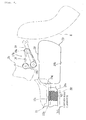
- a rear suspension 17 is disposed between the rear arm 7 and the vehicle body frame 2.
- the rear suspension 17 has a damper 17a whose upper end is connected with a cross pipe (not shown), and a link mechanism 17b connected with the lower end of the damper 17a.
- the link mechanism 17b has a triangular link member 18 connected with the rear arm bracket 2b, and a link arm 19 whose front end is connected with a lower end 18b of the link member 18.
- the rear end of the link arm 19 is connected with the rear arm 7.
- the lower end of the damper 17a is connected with a rear end 18a of the link member 18 (see Figs. 1 and 4).
- the front ends of two-forked foot rest brackets 20, 20 extending toward the rear are fixed to the lower portions of the left and right rear arm brackets 2b, 2b.
- Foot rests 21, 21 are attached to the rear ends of the left and right foot rest brackets 20, 20.
- a brake pedal 22 is attached to the inside of the foot rest 21 of the left foot rest bracket 20 such that the brake pedal 22 can vertically swing.
- a master cylinder 23 is connected with the brake pedal 22.
- An engine 15 is suspended and supported by the left and right main frames 2a, 2a and the rear arm brackets 2b, 2b.
- the engine 15 is a water-cooled type 4-cycle parallel 4-cylinder engine, and is mounted with its cylinder axis inclined toward the front.
- An output shaft 15a of the engine 15 is connected with the rear wheel 8 by a gearing chain 24.
- An air intake unit is disposed above the engine 15, and an exhaust system 25 is provided below the engine 15.
- the engine 15 is positioned below the lower surface of the main frame 2a so that the center of gravity of the vehicle is located at a low position.
- An air cleaner (not shown) having a large capacity is provided in a space between the engine 15 and the fuel tank 10, which is produced as a result of arrangement of the engine 15 in this manner.
- the exhaust system 25 has an exhaust pipe unit 25a connected with the engine 15 and a muffler unit 26 connected with the exhaust pipe unit 25a.
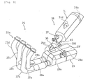
- the exhaust pipe unit 25a is constituted by four exhaust pipes 27a through 27d which extend downward through the front region of the engine 15, turn toward the rear below an oil pan 15b of the engine 15, and then further extend toward the rear, and a pair of left and right junction pipes 28a and 28b.
- the left junction pipe 28a unifies the left two exhaust pipes 27a and 27b into one pipe
- the right junction pipe 28b unifies the right two exhaust pipes 27c and 27d into one pipe, respectively.
- the inside two exhaust pipes 27b and 27c communicate with each other at an intermediate position through a communicating pipe 27e.
- the left and right junction pipes 28a and 28b extend toward the rear along the bottom surface of the oil pan 15b.
- Concaves 15c, 15c are formed on the bottom of the oil pan 15b, and the upper portions of the left and right junction pipes 28a, 28b are provided within the concaves 15c, 15c, respectively (see Figs. 4 and 5).
- This structure allows the engine 15 to be disposed at a further lower position while securing the minimum road clearance from the left and right junction pipes 28a and 28b.
- the muffler unit 26 has a first muffler 29 connected with the left and right junction pipes 28a and 28b, and a second muffler 31 connected with the first muffler 29 via a connecting pipe (connecting passage) 30.
- the first muffler 29 is a substantially rectangular solid component which is formed by combining left and right halves.
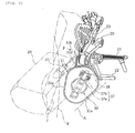
- the first muffler 29 is interposed between the oil pan 15b of the engine 15 and the rear wheel 8, and disposed to be positioned below the foot rest 21.
- the first muffler 29 is suspended and supported by a cross frame member 2b' of the rear arm bracket 2b as a part of the vehicle body frame using left and right attachment brackets 29d, 29d provided on the first muffler 29.
- a rear half 29' of the first muffler 29 positioned at the back of the link member 18 expands upward in such a range that the rear half 29' does not interfere with the link arm 19.
- This structure expands the capacity of a rear expansion chamber b which will be described later.
- the second muffler 31 is substantially cylindrical, and is disposed on the right side of the rear wheel 8.
- the second muffler 31 extends diagonally upward such that the major part of the second muffler 31 including a discharge port 31 b is disposed within the projection plane of the rear wheel 8 as viewed from the side of the vehicle.
- the second muffler 31 is arranged in such a position that the upper end plane of the discharge port 31 b and the upper end plane of the rear arm 7 are substantially at the same level as viewed from the side of the vehicle (see Fig. 1).
- the second muffler 31 is suspended and supported by the foot rest bracket 20 via an attachment member 31 d formed on the second muffler 31.
- Inclined portions 29a, 29a are formed on the left and right lower edges of the first muffler 29 to increase the angle of bank as viewed from the front of the vehicle.
- the inclination of the left and right inclined portions 29a rises toward the outside in the vehicle width direction.
- the height of the first muffler 29 is determined such that the lowest portion of a bottom surface 29b is substantially in correspondence with a line HL indicating a minimum road clearance H (see Figs. 1 and 4).
- the minimum road clearance H herein refers to a clearance between the lowest portion of the vehicle except for the tires and the road surface in the state that the vehicle stands with no load.
- the minimum road clearance H is established to the lowest possible position where the lowest portion of the vehicle does not contact the road surface when the front and rear wheels are at the maximum stroke, or to the lowest possible position where the lowest portion of the vehicle does not contact the boundary between a load-carrying platform of a truck or the like and an inclined passage when the inclined passage is used to place the vehicle on the load-carrying platform for transportation of the vehicle.
- the first muffler 29 in this embodiment is disposed at the lowest possible position where the muffler 29 does not contact the road surface at the time of the maximum stroke or other occasions. This structure therefore contributes to the lowering of the position of the center of gravity of the vehicle.
- the second muffler 31 has a substantially triangular shape having left and right inclined sides 31 a, 31 a as viewed in the cross-sectional view.
- the right inclined side 31 a is disposed to be inclined substantially at the same angle as that of the inclined portion 29a of the first muffler 29.
- the exhaust pipe unit 25a, the first and second mufflers 29 and 31, and all other components of the exhaust system which will be discussed later are disposed within an oblique line A indicating the angle of bank.
- the inside space of the first muffler 29 is divided by a partition wall 35 into a second expansion chamber a provided at the front and the first expansion chamber b provided at the rear.
- the second and first expansion chambers a and b have approximately the same capacity, and communicate with each other through a second communicating pipe 44.
- Glass wools 36, 36 are affixed to the inner surfaces of the second and first expansion chambers a and b so as to reduce exhaust noise and prevent temperature increase due to exhaust gas and generation of shell noise.
- the left and right junction pipes 28a and 28b are connected with a front wall 29g of the first muffler 29.
- the left and right junction pipes 28a and 28b are connected with a first communicating pipe 52 which extends from the front wall 29g of the first muffler 29 through the second expansion chamber a, penetrates through the partition wall 35, and opens within the first expansion chamber b.
- the rear end of the first communicating pipe 52 is air-tightly connected with the partition wall 35.
- An exhaust outlet 50b is formed on a right wall 29h of the second expansion chamber a in the first muffler 29.
- An upstream port 30a of the connecting pipe 30 is connected to the exhaust outlet 50b to communicate therewith.
- a downstream port 30b of the connecting pipe 30 is connected to a front wall 31g of the second muffler 31 to communicate therewith.
- An exhaust valve 37 is disposed within the connection pipe 30.
- the exhaust pipe 37 is constituted by a valve stem 37b which penetrates through the connecting pipe 30 in the radial direction and a valve plate 37a which is fixed to the valve stem 37b to vary the passage area in the connecting pipe 30.
- the valve stem 37b is disposed with inclination such that the valve stem 37b passes the center of the left and right inclined sides 31 a, 31 a and that the upper end of the valve stem 37b is positioned outside.
- a driving cable 39 is connected with the valve stem 37b via a pulley 38.
- the driving cable 39 extends upward along the inner surface of the rear arm bracket 2b to be connected with a not-shown driving motor (see Figs. 2 and 3).
- the exhaust valve 37 closes the passage at the time of the low-speed revolution including the time of engine start-up, and opens the passage at the time of high-speed revolution.
- the exhaust valve 37 is covered by a cover 40 which is provided to be continued to the second muffler 31.
- the cover 40 therefore provides an external appearance of the first and second mufflers 29 and 31 which looks as if they were formed integrally with each other.
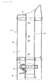
- a second catalyst 44a is provided within the second communicating pipe 44 disposed at the boundary between the first expansion chamber b and the second expansion chamber a in the first muffler 29.
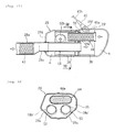
- the second catalyst 44a has a wide oblong shape which has a major axis extending in the vehicle width direction as viewed in the transverse cross-sectional view (see Fig. 12).
- the second communicating pipe 44 is air-tightly fixed to the partition wall 35, and penetrates through the partition wall 35 to connect the first expansion chamber b and the second expansion chamber a such that these chambers can communicate with each other.
- a detection section 45a of an oxygen sensor 45 is inserted into the first expansion chamber b of the first muffler 29 and attached to the chamber b.
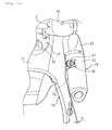
- the oxygen sensor 45 is fitted to a boss 29f formed on the right edge of the upper wall of the first muffler 29, and is disposed in such a position as to be directed toward the inside front F of the right foot rest 21.
- Leads 45b connected with the oxygen sensor 45 pass through the inside of the brake pedal 22, and extend along the driving cable 39. Then, the leads 45b are tied up with the driving cable 39 and clamped to the foot rest bracket 20.
- Exhaust gas passes through the respective exhaust pipes 27a through 27d and reaches the left and right junction pipes 28a and 28b, where the gas is purified by the first catalyst 43 and flows into the first expansion chamber b. Then, the exhaust gas coming from the first expansion chamber b is purified by the second catalyst 44a while passing therethrough, and flows into the second expansion chamber a. Thereafter, the exhaust gas coming from the second expansion chamber a flows through the connecting pipe 30 into the second muffler 31. Finally, the exhaust gas is discharged through the discharge port 31 b of the second muffler 31.
- the first muffler 29 connected with the left and right junction pipes 28a and 28b is interposed between the oil pan 15b of the engine 15 and the rear wheel 8.
- the second muffler 31 connected with the first muffler 29 is disposed on the right side of the rear wheel 8.
- the inclined portions 29a, 29a for increasing the angle of bank are formed on the left and right lower edges of the first muffler 29.
- the inclined portions 31 a having substantially the same angle as that of the inclined portions 29a of the first muffler 29 are formed on the second muffler 31.
- a sufficient angle of bank is secured with the center of gravity of the vehicle located at a low position. Thus, both running stability and maneuverability can be enhanced.
- the first muffler 29 is disposed between the oil pan 15b and the rear wheel 8 and below the foot rest 21.
- the first muffler 29 can be disposed while effectively utilizing the vacant space with a sufficient angle of bank secured, which increases capacities of the second and first expansion chambers a and b.
- the bottom surface of the first muffler 29 is located substantially at the same level as that of the minimum road clearance, the position of the center of gravity of the vehicle can be further lowered.
- the size of the second muffler 31 can be decreased.
- the major part of the second muffler 31 including the discharge port 31 b can be disposed within the projection plane of the rear wheel 8. Therefore, the area around the rear region of the vehicle can be tightly arranged compared with the structure where the muffler projects from the rear wheel 8, which provides design variations.
- the second muffler 31 is located at a low position in this arrangement, which also contributes to the lowering of the center of gravity.
- the inside of the first muffler 29 is divided by the partition wall 35 into the second expansion chamber a and the first expansion chamber b, and the left and right junction pipes 28a and 28b penetrate through the second expansion chamber a via the first communicating pipe 52 and open within the first expansion chamber b. Since the length of the exhaust pipe unit is extended substantially by the portions passing through the second expansion chamber a, a sufficient length of the expansion pipe unit 25a can be secured. Accordingly, the torque in the medium speed range can be enhanced.
- the left and right junction pipes 28a and 28b are connected with the front wall 29g of the first muffler 29, and the upstream port 30a and the downstream port 30b of the connecting pipe 30 are connected with the right wall 29h of the first muffler 29 and the front wall 31 g of the second muffler 31, respectively.
- the first and second mufflers 29 and 31 and the exhaust pipe unit 25a can be arranged in a balanced manner.
- the first catalyst 43 is disposed in the left and right junction pipe 28a and 28b in the vicinity of the upstream portion of the first muffler 29, and the second catalyst 44a is disposed at the boundary between the first expansion chamber b and the second expansion chamber a of the first muffler 29.
- the first catalyst 43 is disposed within the large-diameter portions 28a' and 28b' in the exhaust junction pipes 28a and 28b, increase in flow passage resistance can be prevented. Moreover, since the first catalyst 43 is located upstream of the first muffler 29, i.e., near the engine 15, activation speed of the catalyst 43 at the time of engine start-up can be increased. Furthermore, since the large-diameter portions 28a' and 28'b are provided within the oblique line A indicating the angle of bank, narrowing of the angle of bank is prevented.
- the detection section 45a of the hydrogen sensor 45 since the detection section 45a of the hydrogen sensor 45 is inserted into the first expansion chamber b of the first muffler 29, the detection section 45a detects the oxygen concentration of the exhaust gas having passed through the first catalyst 43. It is therefore possible to securely detect the air fuel ratio around the stoichiometry at which all NOX, CO, and HC included in the exhaust gas can be effectively purified.
- the leads 45b of the oxygen sensor 45 which extend through the inside of the foot rest 21 along the rear arm bracket 2b can be provided together with the driving cable 38 of the exhaust valve 37, leads of a brake lamp switch and the like. Thus, no dedicated bracket and clamp for the leads 45b of the oxygen sensor 45 are required.
- the exhaust valve 37 for varying the passage area is disposed within the connecting pipe 30.
- the exhaust valve 37 closes the passage at the time of the low-speed revolution including the time of engine start-up, and opens the passage at the time of high-speed revolution. Accordingly, the engine output is increased, while noise generated in the low-revolution operational range is reduced.
- Figs. 13 through 19 are figures for explaining an exhaust system of a motorcycle in a second embodiment.
- reference numerals similar to those in Figs. 1 through 12 refer to similar or corresponding components.
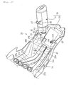
- the exhaust system 25 in this embodiment includes: the exhaust pipe unit 25a connected with the engine 15; the first muffler 29 disposed below the engine and attached to the cross frame member 2b' of the rear arm bracket 2b as a part of the vehicle body frame; and the second muffler 31 connected with the first muffler 29 via connecting pipes 60 and 61 and disposed on the right side of the rear wheel 8.
- the basic structure of the exhaust system 25 in this embodiment is substantially the same as that in the first embodiment.
- the first muffler 29 has: a substantially rectangular solid outside wall member 50 which is long in the front-to-rear direction; a pair of left and right exhaust inlets 50a formed on the front wall of the outside wall member 50; the partition wall 35 for dividing the inside of the outside wall member 50 into the second expansion chamber a formed at the front and the first expansion chamber b formed at the rear; and the exhaust outlet 50b as a single opening formed on the right surface of the outside wall member 50 near the front to communicate with the second expansion chamber a.
- the second and first expansion chambers a and b of the first muffler 29 communicate with each other through a second communicating pipe 44 which penetrates through the partition plate 35.
- the left and right exhaust inlets 50a and the first expansion chamber b communicate with each other through a pair of the left and right first communicating pipes 52, 52.
- the left and right junction pipes 28a and 28b are connected with the left and right first communicating pipes 52.
- the left and right first communicating pipes 52, 52 are arranged in parallel in the vehicle width direction and within the lower region of the first muffler 29.
- the second communicating pipe 44 is disposed above the first communicating pipes 52, and has a long-hole shape which is long in the vehicle width direction as viewed in the transverse cross-sectional view.
- the exhaust outlet 50b is formed so that it faces to the downstream end of the second communicating pipe 44 of the second expansion chamber a, and is located above the first communicating pipes 52.
- the second muffler 31 includes: an outer cylindrical member 55 which is substantially cylindrical; front and rear lids 56 and 57 for closing both end openings of the outer cylindrical member 55; and an inner cylindrical member 58 which is made of punching metal and inserted into the outer cylindrical member 55 such that the inner cylindrical member 58 penetrates through the front and rear lids 56 and 57.
- a third expansion chamber c is formed by the outer cylindrical member 55 and the inner cylindrical member 58, and the inside of the third expansion chamber c is filled with not-shown sound absorbing material such as glass wool.
- the first connecting pipe 60 is connected with the exhaust outlet 50b formed on the right wall 29h of the first muffler 29.
- the second connecting pipe 61 communicating with the inner cylindrical member 58 is connected with the front lid 56 of the second muffler 31.
- the first and second connecting pipes 60 and 61 are connected with each other, and constitute a connecting passage for connecting the side wall rear portion of the first muffler 29 and the front wall of the second muffler 31 such that they can communicate with each other.
- the exhaust valve 37 described above is disposed in the second connecting pipe 61.
- a heat insulating cover 65 for covering the outside-vehicle portions of the second connecting pipe 61 and the exhaust valve 37 is attached to the second muffler 31.
- the heat insulating cover 65 protects an actuator of the exhaust valve 37 from the external force, and prevents transmission of heat generated in the second muffler 31 to the legs of the rider.
- a bracket 66 is attached to the upper surface of the outer cylindrical member 55 of the second muffler 31.
- the bracket 66 is fixed to the foot rest bracket 20 describe above via a damper 67.
- the second muffler 31 is disposed along a right arm member 7a of the rear arm 7 in the vicinity thereof.
- a clearance concave 7b is formed on the right arm member 7a to prevent interference with the second muffler 31.
- the clearance concave 7b provides a predetermined clearance S between the outer peripheral surface of the second muffler 31 and the right arm member 7a.
- the rear suspension 17 described above is interposed between the rear arm 7 and the vehicle body frame 2.
- the damper 17a of the rear suspension 17 is positioned within an insertion hole 7d formed at the center of a pivot base 7c of the rear arm 7 in the vehicle width direction.
- the rear suspension 17 is disposed so as to be positioned above the fist muffler 29.
- the lower portion and the left and right sides of the first muffler 29 are covered by the under cowl 14 described above.
- a front opening 14b for introducing flow of air generated during running of the vehicle is formed on the front surface of the under cowl 14.
- a discharge opening 14a for discharging the introduced air to the outside is formed on the bottom of the under cowl 14.
- the discharge opening 14a has a front-to-rear length extending from the front ends of the left and right junction pipes 28a and 28b to the rear end of the first muffler 29.
- the air introduced through the front opening 14b into the under cowl 14 is supplied to the respective exhaust pipes 27a through 27d, the left and right junction pipes 28a and 28b, and the outer surface of the first muffler 29.
- the air having cooled these components is discharged through the discharge opening 14a to the outside.
- the first muffler 29 is disposed below the engine 15.
- the center of gravity of the vehicle body is located at a lower position. Accordingly, the rolling inertia can be reduced, and the weight of the vehicle body can be easily balanced in the front-to-rear direction.
- the first and second mufflers 29 and 31 are separately disposed such that the first muffler 29 is below the engine 15 and that the second muffler 31 is in the vicinity of the right side of the rear wheel 8, the sufficient capacity of the first muffler 29 is secured without interference with the rear wheel 8. Moreover, as the distance from the front wheel 5 is increased, the exhaust pipe unit length is enlarged accordingly. Therefore, engine performance of a vehicle including a high-output engine can be enhanced.
- the first and second mufflers 29 and 31 can be separately disposed without increasing the distance therebetween.
- This structure provides compact arrangement of the first and second mufflers 29 and 31 while preventing interference with the engine 15, the rear wheel 8, the rear arm 7 and other components.
- the left and right first communicating pipes 52, 52 are positioned within the lower region of the first muffler 29, and the second communicating pipe 44 is located above the first communicating pipes 52.
- the transverse cross section of the second communicating pipe 44 has a long-hole shape which is long in the vehicle width direction. Accordingly, the length of the first muffler 29 in the vehicle width direction can be reduced, and enlargement in the size of the first muffler 29 can be prevented when the first muffler 29 is used as a common muffler for the respective cylinders.
- the rear suspension 17 is disposed above the first muffler 29.
- the rear suspension 17 can be provided while effectively utilizing the vacant space above the compact first muffler 29.
- the heat insulating cover 65 for covering the outside-vehicle portions of the connecting pipe 61 and the exhaust valve 37 is attached to the second muffler 31. It is therefore possible to prevent damage to the actuator of the exhaust valve 37 by the external force, and transmission of heat generated in the second muffler 31 to the legs of the rider.
- the discharge opening 14a through which flow of air generated during running of the vehicle is discharged to the outside is formed on the under cowl 14 which covers the lower region of the first muffler 29.
- the discharge efficiency of air introduced into the under cowl 14 can be increased, and also the cooling efficiency of the exhaust pipe unit 25a and the first muffler 29 can be enhanced.
- an exhaust system of a motorcycle including: an exhaust pipe unit connected with an engine; and a muffler unit connected with the exhaust pipe unit.
- the exhaust pipe unit passes through the lower portion of the engine.
- the muffler unit includes a first muffler connected with the exhaust pipe unit and disposed between the lower portion of the engine and a rear wheel, and a second muffler connected with the first muffler and disposed near the side of the rear wheel.
- Inclined portions are formed on the left and right sides of the first muffler such that the inclination of the inclined portions rises toward the outside in the vehicle width direction as viewed from the front of the vehicle.
- the second muffler extends to the rear of the vehicle and is inclined at an angle approximately equal to that of the inclined portions of the first muffler.
- the first muffler connected with the exhaust pipe unit is interposed between the lower portion of the engine and the rear wheel; the second muffler connected with the first muffler is disposed near the side of the rear wheel; inclined portions are formed on the left and right sides of the first muffler; and the second muffler is inclined at the angle approximately equal to that of the inclined portions of the first muffler. Accordingly, a sufficient angle of bank can be secured while lowering the position of the center of gravity of the vehicle body, and thus both running stability and maneuverability can be enhanced. Moreover, since the exhaust pipe unit passes through the lower portion of the engine, a sufficient length of the exhaust pipe unit can be obtained.
- the first muffler is disposed between an oil pan of the engine and the rear wheel as viewed from the side of the vehicle.
- the second muffler extends diagonally upward to the rear with inclination which rises toward the rear, and at least a discharge port of the second muffler lies within the projection plane of the rear wheel in the vehicle width direction as viewed from the side of the vehicle.
- the upper end plane of the discharge port of the second muffler is disposed approximately at the same level as that of the upper end plane of a rear arm which supports the rear wheel as viewed from the side of the vehicle.
- the first muffler is divided into a first expansion chamber formed at the rear, a second expansion chamber formed at the front, and a rear expansion chamber
- the exhaust pipe unit penetrates through the second expansion chamber and opens within the first expansion chamber
- the first and second expansion chambers communicated with each other through a communicating pipe.
- an upstream port of a connecting passage which communicates with the second expansion chamber is connected with the side wall of the first muffler, and a downstream port of the connecting passage is connected with the front wall of the second muffler so as to communicate therewith.
- a first catalyst is provided within the exhaust pipe unit in the vicinity of the upstream portion of the first muffler, and a second catalyst is provided within the communicating pipe for connecting the first and second expansion chamber such that these chambers can communicate with each other.
- the portion of the exhaust pipe unit in which the first catalyst is provided lies inside the angle of bank as viewed from the front of the vehicle.
- a detection section of an oxygen sensor is inserted into the first expansion chamber of the first muffler.
- the oxygen sensor is so positioned as to be directed to the inside front of a foot rest.
- the first muffler is disposed below the engine and attached to a vehicle body frame
- the second muffler is disposed near the side of the rear wheel
- a portion of the side wall of the first muffler near the second muffler and the front wall of the second muffler is connected through a connecting passage such that the first and second mufflers can communicate with each other.
- the first muffler includes a first expansion chamber formed at the rear, a second expansion chamber formed at the front and connected with the exhaust pipe unit, a first connecting pipe for connecting the exhaust pipe unit and the first expansion chamber within the second expansion chamber, and a second connecting pipe for connecting the first expansion chamber and the second expansion chamber, and the second muffler includes a third expansion chamber connected with the second expansion chamber.
- the first connecting pipe may be disposed in the lower region of the first muffler, and the second connecting pipe may be disposed in the upper region of the first muffler.
- the transverse cross section of the second connecting pipe may have a long-hole shape which is long in the vehicle width direction.
- the exhaust pipe unit may have a plurality of exhaust pipes, and at least two junction pipes for unifying the respective exhaust pipes, and the respective junction pipes may be connected with the first muffler and arranged in parallel in the vehicle width direction.
- a catalyst may be provided within the exhaust pipe unit at a portion upstream of a connecting portion between the exhaust pipe unit and the first muffler.
- a rear suspension for connecting a rear arm for supporting the rear wheel and the vehicle body frame may be disposed above the first muffler.
- the second muffler may be disposed along a rear arm for supporting the rear wheel and a clearance concave for providing a predetermined clearance between the rear arm and the outer periphery of the second muffler may be formed on the rear arm.
- the lower portion of the first muffler may be covered by an under cowling, and a front opening through which flow of air generated during running of the motorcycle is introduced and a discharge opening through which the air is discharged may be formed on the under cowling.
- a connecting passage for connecting the first muffler and second muffler may be equipped and an exhaust valve for varying the passage area may be disposed within the connecting passage.
- a connecting passage for connecting the first muffler and second muffler may be equipped and a heat insulating cover for covering at least the outside-vehicle portion of the connecting passage may be provided on the second muffler.
- an exhaust valve for varying the passage area may be disposed within the connecting passage and the heat insulating cover may cover the exhaust valve as well as the connecting passage.
- a muffler unit 26 includes a first muffler 29 connected with the exhaust pipe unit 25a and disposed between the engine 15 and a rear wheel 8, and a second muffler 31 connected with the first muffler 29 and disposed near the side of the rear wheel 8.
- Inclined portions 29a, 29a for increasing an angle of bank are formed on the left and right sides of the first muffler 29 as viewed from the front of the vehicle.
- the second muffler 31 has inclined portions 31 a having an angle approximately equal to that of the inclined portions 29a of the first muffler 29.
Landscapes
- Engineering & Computer Science (AREA)
- Chemical & Material Sciences (AREA)
- Mechanical Engineering (AREA)
- Combustion & Propulsion (AREA)
- General Engineering & Computer Science (AREA)
- Chemical Kinetics & Catalysis (AREA)
- Health & Medical Sciences (AREA)
- Toxicology (AREA)
- Exhaust Silencers (AREA)
- Exhaust Gas After Treatment (AREA)
- Axle Suspensions And Sidecars For Cycles (AREA)
Applications Claiming Priority (3)
| Application Number | Priority Date | Filing Date | Title |
|---|---|---|---|
| JP2005069761 | 2005-03-11 | ||
| JP2005161445 | 2005-06-01 | ||
| JP2005316085A JP2007008442A (ja) | 2005-03-11 | 2005-10-31 | 自動二輪車の排気装置 |
Publications (2)
| Publication Number | Publication Date |
|---|---|
| EP1701009A1 true EP1701009A1 (fr) | 2006-09-13 |
| EP1701009B1 EP1701009B1 (fr) | 2008-01-02 |
Family
ID=36353482
Family Applications (1)
| Application Number | Title | Priority Date | Filing Date |
|---|---|---|---|
| EP06004991A Expired - Lifetime EP1701009B1 (fr) | 2005-03-11 | 2006-03-10 | Motocyclette |
Country Status (6)
| Country | Link |
|---|---|
| US (1) | US7699134B2 (fr) |
| EP (1) | EP1701009B1 (fr) |
| JP (1) | JP2007008442A (fr) |
| AT (1) | ATE382779T1 (fr) |
| DE (1) | DE602006000376T2 (fr) |
| ES (1) | ES2299111T3 (fr) |
Cited By (7)
| Publication number | Priority date | Publication date | Assignee | Title |
|---|---|---|---|---|
| EP1975384A1 (fr) * | 2007-03-30 | 2008-10-01 | HONDA MOTOR CO., Ltd. | Dispositif d'échappement pour moteur de motocyclette |
| EP2055908A3 (fr) * | 2007-11-02 | 2009-09-30 | Honda Motor Co., Ltd. | Système d'échappement de motocyclette |
| EP2105586A1 (fr) * | 2008-03-28 | 2009-09-30 | Yamaha Hatsudoki Kabushiki Kaisha | Support de fixation de silencieux et véhicule de type à enfourcher le comprenant |
| EP2808507A3 (fr) * | 2013-05-31 | 2015-01-21 | Yamaha Hatsudoki Kabushiki Kaisha | Motocyclette |
| CN105386838A (zh) * | 2014-08-22 | 2016-03-09 | 铃木株式会社 | 摩托车的消声器组件 |
| EP3236034A4 (fr) * | 2014-12-19 | 2018-03-28 | Yamaha Hatsudoki Kabushiki Kaisha | Véhicule du type à selle |
| CN113574254A (zh) * | 2019-03-25 | 2021-10-29 | Tvs电机股份有限公司 | 用于机动车辆的动力单元 |
Families Citing this family (37)
| Publication number | Priority date | Publication date | Assignee | Title |
|---|---|---|---|---|
| JP4528297B2 (ja) * | 2003-07-08 | 2010-08-18 | ディーエスエム アイピー アセッツ ビー.ブイ. | コエンザイムq−10の向上した産生 |
| DE102004034206B4 (de) * | 2004-07-14 | 2007-02-22 | J. Eberspächer GmbH & Co. KG | Schalldämpfer für eine Abgasanlage |
| JP4661472B2 (ja) * | 2005-09-12 | 2011-03-30 | スズキ株式会社 | 自動二輪車のカウリング |
| KR101303497B1 (ko) * | 2006-02-02 | 2013-09-03 | 삼성에스디아이 주식회사 | 소음기를 장착한 연료전지 시스템 |
| JP2008111357A (ja) * | 2006-10-30 | 2008-05-15 | Yamaha Motor Co Ltd | 自動二輪車の排気装置 |
| JP2008111356A (ja) * | 2006-10-30 | 2008-05-15 | Yamaha Motor Co Ltd | 自動二輪車の排気装置及び該排気装置を備えた自動二輪車 |
| JP4919864B2 (ja) * | 2007-03-30 | 2012-04-18 | 本田技研工業株式会社 | 鞍乗り型車両用排気装置 |
| JP2009241922A (ja) * | 2007-12-28 | 2009-10-22 | Yamaha Motor Co Ltd | 鞍乗型車両 |
| JP2010196545A (ja) * | 2009-02-24 | 2010-09-09 | Yamaha Motor Co Ltd | 車両 |
| JP5396152B2 (ja) * | 2009-05-22 | 2014-01-22 | 本田技研工業株式会社 | 自動二輪車 |
| JP2011196242A (ja) | 2010-03-19 | 2011-10-06 | Kawasaki Heavy Ind Ltd | 自動二輪車の排気チャンバ |
| JP5801066B2 (ja) * | 2011-03-07 | 2015-10-28 | 本田技研工業株式会社 | エンジンの排気浄化装置 |
| JP5969328B2 (ja) * | 2012-09-04 | 2016-08-17 | 川崎重工業株式会社 | 自動二輪車 |
| JP5993770B2 (ja) * | 2013-03-28 | 2016-09-14 | 本田技研工業株式会社 | 多気筒エンジンの排気装置 |
| JP2014227927A (ja) * | 2013-05-23 | 2014-12-08 | ヤマハ発動機株式会社 | 鞍乗型車両 |
| CN105658510B (zh) * | 2013-11-07 | 2019-12-31 | 川崎重工业株式会社 | 跨乘式车辆的车身框架结构 |
| EP3067263B1 (fr) * | 2013-11-07 | 2020-04-15 | Kawasaki Jukogyo Kabushiki Kaisha | Structure de châssis de véhicule d'un véhicule à enfourcher |
| JP6208556B2 (ja) * | 2013-11-19 | 2017-10-04 | 川崎重工業株式会社 | オイルストレーナおよび車両のオイル貯留装置 |
| DE102013224562A1 (de) * | 2013-11-29 | 2015-06-03 | Bayerische Motoren Werke Aktiengesellschaft | Vorrichtung zur Aufnahme eines Endschalldämpfers eines Zweirads |
| JP5889268B2 (ja) * | 2013-12-04 | 2016-03-22 | 本田技研工業株式会社 | 自動二輪車用排気装置 |
| DE102013113613A1 (de) * | 2013-12-06 | 2015-06-11 | Dr. Ing. H.C. F. Porsche Aktiengesellschaft | Abgasanlage für ein Kraftfahrzeug |
| JP6292095B2 (ja) * | 2014-09-25 | 2018-03-14 | スズキ株式会社 | 鞍乗型車両の排気装置 |
| JP6333199B2 (ja) * | 2015-03-05 | 2018-05-30 | 本田技研工業株式会社 | エンジンの排気装置 |
| JP6454578B2 (ja) * | 2015-03-26 | 2019-01-16 | 本田技研工業株式会社 | 自動二輪車 |
| DE102015220254B4 (de) * | 2015-10-19 | 2017-08-24 | Bayerische Motoren Werke Aktiengesellschaft | Abgasanlage für ein Motorrad und Abgasreinigungssystem mit einer solchen Abgasanlage |
| US10041387B2 (en) * | 2015-12-25 | 2018-08-07 | Honda Motor Co., Ltd. | Exhaust device structure for rocking vehicle |
| JP6623925B2 (ja) * | 2016-05-18 | 2019-12-25 | スズキ株式会社 | 排気ガスセンサの配置構造 |
| JP6701980B2 (ja) * | 2016-06-01 | 2020-05-27 | スズキ株式会社 | 排気ガスセンサの配置構造 |
| WO2019043869A1 (fr) * | 2017-08-31 | 2019-03-07 | 本田技研工業株式会社 | Dispositif d'échappement pour véhicules à selle |
| BR112020006244B1 (pt) * | 2017-09-29 | 2023-04-11 | Honda Motor Co., Ltd | Estrutura de fixação para o sensor de gás de escape |
| JP6474924B2 (ja) * | 2018-01-12 | 2019-02-27 | 本田技研工業株式会社 | エンジンの排気装置 |
| JP7172290B2 (ja) * | 2018-08-29 | 2022-11-16 | スズキ株式会社 | 自動二輪車 |
| JP6831357B2 (ja) * | 2018-10-09 | 2021-02-17 | フタバ産業株式会社 | マフラ |
| JP6730413B2 (ja) * | 2018-12-17 | 2020-07-29 | 本田技研工業株式会社 | 自動二輪車 |
| JP2021091290A (ja) | 2019-12-10 | 2021-06-17 | ヤマハ発動機株式会社 | 車両 |
| JP7563185B2 (ja) * | 2021-01-08 | 2024-10-08 | スズキ株式会社 | 排気装置 |
| CN113847118B (zh) * | 2021-09-10 | 2022-10-18 | 浙江吉利控股集团有限公司 | 一种排气消音器总成主动发声的系统及方法 |
Citations (6)
| Publication number | Priority date | Publication date | Assignee | Title |
|---|---|---|---|---|
| JPS56143311A (en) * | 1980-04-10 | 1981-11-09 | Suzuki Motor Co Ltd | Exhaust gas purifier for internal combustion engine |
| JPS595824A (ja) * | 1982-07-01 | 1984-01-12 | Honda Motor Co Ltd | 自動二輪車の排気消音装置 |
| US4809800A (en) * | 1984-12-10 | 1989-03-07 | Yamaha Hatsudoki Kabushiki Kaisha | Exhaust system for vehicle |
| JPH05231145A (ja) * | 1992-02-21 | 1993-09-07 | Suzuki Motor Corp | 自動二輪車用エンジンのエキゾーストシステム |
| DE4330129A1 (de) * | 1993-09-06 | 1995-03-09 | Bayerische Motoren Werke Ag | Abgasanlage einer Brennkraftmaschine |
| EP1247955A1 (fr) * | 2001-04-04 | 2002-10-09 | Honda Giken Kogyo Kabushiki Kaisha | Dispositif d'échappement pour une motocyclette |
Family Cites Families (34)
| Publication number | Priority date | Publication date | Assignee | Title |
|---|---|---|---|---|
| US3972685A (en) * | 1973-10-03 | 1976-08-03 | Masanori Hanaoka | Catalyst converter |
| USRE31989E (en) * | 1978-09-29 | 1985-09-24 | Yamaha Hatsudoki Kabushiki Kaisha | Motorcycle engine exhaust system |
| JPS5638515A (en) * | 1979-09-07 | 1981-04-13 | Honda Motor Co Ltd | Exhaust system of multicylinder engine |
| US4553388A (en) * | 1981-11-30 | 1985-11-19 | Honda Giken Kogyo Kabushiki Kaisha | Exhaust gas purification apparatus for an internal combustion engine |
| US4913256A (en) * | 1986-05-30 | 1990-04-03 | Honda Giken Kogyo Kabushiki Kaisha | Motorcycle |
| US4776422A (en) * | 1986-05-30 | 1988-10-11 | Honda Giken Kogyo Kabushiki Kaisha | Motorcycle with fairing |
| US4913260A (en) * | 1988-01-11 | 1990-04-03 | Tenneco Inc. | Gas silencing system with controlling sound attenuation |
| US4860538A (en) * | 1988-02-23 | 1989-08-29 | Yamaha Hatsudoki Kabushiki Kaisha | Exhaust gas control means for motorcycle and the like |
| US4858722A (en) * | 1988-09-22 | 1989-08-22 | Abbe David C | Self-contained muffler attachment and conversion kit for small two-cycle engines |
| US4964484A (en) * | 1989-04-06 | 1990-10-23 | Buell Motor Company, Inc. | Motorcycle fairing |
| JP3046435B2 (ja) * | 1991-09-11 | 2000-05-29 | ヤマハ発動機株式会社 | 自動二輪車の酸素センサー保護装置 |
| US5351481A (en) * | 1992-06-26 | 1994-10-04 | Flowmaster, Inc. | Muffler assembly with balanced chamber and method |
| US5519994A (en) * | 1994-02-18 | 1996-05-28 | Tennessee Gas Pipeline Company | Muffler with inlet pipe equalizer |
| JP2971341B2 (ja) * | 1994-10-19 | 1999-11-02 | 本田技研工業株式会社 | 車両の排気装置 |
| US5853216A (en) * | 1996-03-05 | 1998-12-29 | Barg; James A. | Air shield |
| JP3753800B2 (ja) * | 1996-07-25 | 2006-03-08 | 本田技研工業株式会社 | 自動二輪車用マフラー |
| JP3712800B2 (ja) * | 1996-09-20 | 2005-11-02 | 本田技研工業株式会社 | 自動二輪車における排気系のカバー装置 |
| JPH10131746A (ja) * | 1996-10-31 | 1998-05-19 | Honda Motor Co Ltd | 車両の排気装置 |
| US6193004B1 (en) * | 1999-07-29 | 2001-02-27 | Harley-Davidson Motor Company | Motorcycle exhaust system |
| JP3835075B2 (ja) * | 1999-09-16 | 2006-10-18 | スズキ株式会社 | 自動二輪車の排気装置 |
| CA2351293A1 (fr) * | 2000-06-22 | 2001-12-22 | Bombardier Inc. | Embarcation comprenant un circuit d'echappement ameliore |
| US6467569B2 (en) * | 2001-01-19 | 2002-10-22 | Supertrapp Industries | Spark arresting muffler with exhaust path parallel to muffler centerline |
| JP3493344B2 (ja) * | 2001-01-23 | 2004-02-03 | 川崎重工業株式会社 | 騎乗型不整地走行車の排気装置 |
| JP3938481B2 (ja) * | 2001-08-22 | 2007-06-27 | 本田技研工業株式会社 | 自動二輪車の排気装置 |
| US6804955B2 (en) * | 2001-09-26 | 2004-10-19 | Darryl C. Bassani | Dual motorcycle exhaust system |
| US6584767B1 (en) * | 2001-11-09 | 2003-07-01 | Steve Koenig | Exhaust diverter |
| JP2004183622A (ja) * | 2002-12-06 | 2004-07-02 | Honda Motor Co Ltd | 内燃機関の排気消音器 |
| JP4049379B2 (ja) * | 2003-08-27 | 2008-02-20 | 本田技研工業株式会社 | 自動二輪車の排気制御装置 |
| JP4272029B2 (ja) * | 2003-09-30 | 2009-06-03 | 本田技研工業株式会社 | 自動二輪車の排気制御装置 |
| JP4207790B2 (ja) * | 2004-02-02 | 2009-01-14 | トヨタ自動車株式会社 | 車体下部構造 |
| JP4424593B2 (ja) * | 2004-04-27 | 2010-03-03 | 本田技研工業株式会社 | 自動二輪車の排気装置 |
| US7347045B2 (en) * | 2004-06-30 | 2008-03-25 | Harley-Davidson Motor Company Group, Inc. | Motorcycle dynamic exhaust system |
| JP4455962B2 (ja) * | 2004-09-13 | 2010-04-21 | 川崎重工業株式会社 | 自動二輪車の排気装置 |
| USD523787S1 (en) * | 2004-10-29 | 2006-06-27 | Kuryakyn Holdings, Inc. | Slip-in heat shield for a gap on motorcycle exhaust pipe |
-
2005
- 2005-10-31 JP JP2005316085A patent/JP2007008442A/ja not_active Withdrawn
-
2006
- 2006-03-10 AT AT06004991T patent/ATE382779T1/de not_active IP Right Cessation
- 2006-03-10 ES ES06004991T patent/ES2299111T3/es not_active Expired - Lifetime
- 2006-03-10 EP EP06004991A patent/EP1701009B1/fr not_active Expired - Lifetime
- 2006-03-10 DE DE602006000376T patent/DE602006000376T2/de not_active Expired - Lifetime
- 2006-03-13 US US11/374,628 patent/US7699134B2/en active Active
Patent Citations (7)
| Publication number | Priority date | Publication date | Assignee | Title |
|---|---|---|---|---|
| JPS56143311A (en) * | 1980-04-10 | 1981-11-09 | Suzuki Motor Co Ltd | Exhaust gas purifier for internal combustion engine |
| JPS595824A (ja) * | 1982-07-01 | 1984-01-12 | Honda Motor Co Ltd | 自動二輪車の排気消音装置 |
| US4809800A (en) * | 1984-12-10 | 1989-03-07 | Yamaha Hatsudoki Kabushiki Kaisha | Exhaust system for vehicle |
| JPH05231145A (ja) * | 1992-02-21 | 1993-09-07 | Suzuki Motor Corp | 自動二輪車用エンジンのエキゾーストシステム |
| DE4330129A1 (de) * | 1993-09-06 | 1995-03-09 | Bayerische Motoren Werke Ag | Abgasanlage einer Brennkraftmaschine |
| EP1247955A1 (fr) * | 2001-04-04 | 2002-10-09 | Honda Giken Kogyo Kabushiki Kaisha | Dispositif d'échappement pour une motocyclette |
| JP2002303133A (ja) | 2001-04-04 | 2002-10-18 | Honda Motor Co Ltd | 自動二輪車の排気系構造 |
Non-Patent Citations (3)
| Title |
|---|
| PATENT ABSTRACTS OF JAPAN vol. 006, no. 026 (M - 112) 16 February 1982 (1982-02-16) * |
| PATENT ABSTRACTS OF JAPAN vol. 008, no. 090 (M - 292) 25 April 1984 (1984-04-25) * |
| PATENT ABSTRACTS OF JAPAN vol. 017, no. 686 (M - 1529) 15 December 1993 (1993-12-15) * |
Cited By (10)
| Publication number | Priority date | Publication date | Assignee | Title |
|---|---|---|---|---|
| EP1975384A1 (fr) * | 2007-03-30 | 2008-10-01 | HONDA MOTOR CO., Ltd. | Dispositif d'échappement pour moteur de motocyclette |
| US7828114B2 (en) | 2007-03-30 | 2010-11-09 | Honda Motor Co., Ltd. | Exhaust device for motorcycle engine |
| EP2055908A3 (fr) * | 2007-11-02 | 2009-09-30 | Honda Motor Co., Ltd. | Système d'échappement de motocyclette |
| US8033357B2 (en) | 2007-11-02 | 2011-10-11 | Honda Motor Co., Ltd. | Exhaust system for a motorcycle, and motorcycle incorporating same |
| EP2105586A1 (fr) * | 2008-03-28 | 2009-09-30 | Yamaha Hatsudoki Kabushiki Kaisha | Support de fixation de silencieux et véhicule de type à enfourcher le comprenant |
| EP2808507A3 (fr) * | 2013-05-31 | 2015-01-21 | Yamaha Hatsudoki Kabushiki Kaisha | Motocyclette |
| CN105386838A (zh) * | 2014-08-22 | 2016-03-09 | 铃木株式会社 | 摩托车的消声器组件 |
| CN105386838B (zh) * | 2014-08-22 | 2019-07-23 | 铃木株式会社 | 摩托车的消声器组件 |
| EP3236034A4 (fr) * | 2014-12-19 | 2018-03-28 | Yamaha Hatsudoki Kabushiki Kaisha | Véhicule du type à selle |
| CN113574254A (zh) * | 2019-03-25 | 2021-10-29 | Tvs电机股份有限公司 | 用于机动车辆的动力单元 |
Also Published As
| Publication number | Publication date |
|---|---|
| US7699134B2 (en) | 2010-04-20 |
| US20060201742A1 (en) | 2006-09-14 |
| ES2299111T3 (es) | 2008-05-16 |
| DE602006000376T2 (de) | 2008-05-08 |
| DE602006000376D1 (de) | 2008-02-14 |
| EP1701009B1 (fr) | 2008-01-02 |
| JP2007008442A (ja) | 2007-01-18 |
| ATE382779T1 (de) | 2008-01-15 |
Similar Documents
| Publication | Publication Date | Title |
|---|---|---|
| EP1701009B1 (fr) | Motocyclette | |
| CN103670639B (zh) | 摩托车的排气系统 | |
| KR100568097B1 (ko) | 자동이륜차의 배기 제어장치 | |
| JP4545624B2 (ja) | ステアリングダンパ取り付け構造 | |
| CN101793187B (zh) | 跨骑型车辆的消音器罩 | |
| US20100213000A1 (en) | Vehicular muffler and motorcycle incorporating same | |
| JP2007176466A (ja) | 自動2輪車用ブレーキ制御装置の配置構造 | |
| JP2017150311A (ja) | エンジンユニット及び鞍乗型車両 | |
| JP2013193626A (ja) | 鞍乗り型車両のキャニスター配置構造 | |
| JP7367748B2 (ja) | 自動二輪車の車体構造 | |
| JP3889236B2 (ja) | 自動二輪車の排気系構造 | |
| JP2010228738A (ja) | 自動二輪車 | |
| JP5469821B2 (ja) | 車両 | |
| US20080116004A1 (en) | Motorcycle Exhaust System and Motorcycle Provided with Exhaust System | |
| CN101314390B (zh) | 摩托车排气系统 | |
| JP2017150309A (ja) | エンジンユニットおよび鞍乗型車両 | |
| JP5993902B2 (ja) | スクータ型車両の排気装置 | |
| JP4473804B2 (ja) | 自動二輪車の排気装置 | |
| JP4681969B2 (ja) | 自動二輪車のリアクッション配置構造 | |
| CN100523444C (zh) | 摩托车的排气装置 | |
| JP2018115652A (ja) | 排気ガスセンサの配置構造 | |
| JP4693733B2 (ja) | 自動二輪車の触媒配置構造 | |
| JP2005188316A (ja) | 自動二輪車の排気装置 | |
| KR100930322B1 (ko) | 모터 사이클 | |
| JP4654763B2 (ja) | エンジンの排気装置 |
Legal Events
| Date | Code | Title | Description |
|---|---|---|---|
| PUAI | Public reference made under article 153(3) epc to a published international application that has entered the european phase |
Free format text: ORIGINAL CODE: 0009012 |
|
| 17P | Request for examination filed |
Effective date: 20060621 |
|
| AK | Designated contracting states |
Kind code of ref document: A1 Designated state(s): AT BE BG CH CY CZ DE DK EE ES FI FR GB GR HU IE IS IT LI LT LU LV MC NL PL PT RO SE SI SK TR |
|
| AX | Request for extension of the european patent |
Extension state: AL BA HR MK YU |
|
| 17Q | First examination report despatched |
Effective date: 20061018 |
|
| AKX | Designation fees paid |
Designated state(s): AT BE BG CH CY CZ DE DK EE ES FI FR GB GR HU IE IS IT LI LT LU LV MC NL PL PT RO SE SI SK TR |
|
| GRAP | Despatch of communication of intention to grant a patent |
Free format text: ORIGINAL CODE: EPIDOSNIGR1 |
|
| GRAS | Grant fee paid |
Free format text: ORIGINAL CODE: EPIDOSNIGR3 |
|
| GRAA | (expected) grant |
Free format text: ORIGINAL CODE: 0009210 |
|
| AK | Designated contracting states |
Kind code of ref document: B1 Designated state(s): AT BE BG CH CY CZ DE DK EE ES FI FR GB GR HU IE IS IT LI LT LU LV MC NL PL PT RO SE SI SK TR |
|
| REG | Reference to a national code |
Ref country code: GB Ref legal event code: FG4D |
|
| REG | Reference to a national code |
Ref country code: IE Ref legal event code: FG4D |
|
| REG | Reference to a national code |
Ref country code: CH Ref legal event code: EP |
|
| REF | Corresponds to: |
Ref document number: 602006000376 Country of ref document: DE Date of ref document: 20080214 Kind code of ref document: P |
|
| REG | Reference to a national code |
Ref country code: ES Ref legal event code: FG2A Ref document number: 2299111 Country of ref document: ES Kind code of ref document: T3 |
|
| PG25 | Lapsed in a contracting state [announced via postgrant information from national office to epo] |
Ref country code: SI Free format text: LAPSE BECAUSE OF FAILURE TO SUBMIT A TRANSLATION OF THE DESCRIPTION OR TO PAY THE FEE WITHIN THE PRESCRIBED TIME-LIMIT Effective date: 20080102 Ref country code: NL Free format text: LAPSE BECAUSE OF FAILURE TO SUBMIT A TRANSLATION OF THE DESCRIPTION OR TO PAY THE FEE WITHIN THE PRESCRIBED TIME-LIMIT Effective date: 20080102 |
|
| NLV1 | Nl: lapsed or annulled due to failure to fulfill the requirements of art. 29p and 29m of the patents act | ||
| PG25 | Lapsed in a contracting state [announced via postgrant information from national office to epo] |
Ref country code: CH Free format text: LAPSE BECAUSE OF FAILURE TO SUBMIT A TRANSLATION OF THE DESCRIPTION OR TO PAY THE FEE WITHIN THE PRESCRIBED TIME-LIMIT Effective date: 20080102 Ref country code: LI Free format text: LAPSE BECAUSE OF FAILURE TO SUBMIT A TRANSLATION OF THE DESCRIPTION OR TO PAY THE FEE WITHIN THE PRESCRIBED TIME-LIMIT Effective date: 20080102 Ref country code: FI Free format text: LAPSE BECAUSE OF FAILURE TO SUBMIT A TRANSLATION OF THE DESCRIPTION OR TO PAY THE FEE WITHIN THE PRESCRIBED TIME-LIMIT Effective date: 20080102 Ref country code: IS Free format text: LAPSE BECAUSE OF FAILURE TO SUBMIT A TRANSLATION OF THE DESCRIPTION OR TO PAY THE FEE WITHIN THE PRESCRIBED TIME-LIMIT Effective date: 20080502 Ref country code: LT Free format text: LAPSE BECAUSE OF FAILURE TO SUBMIT A TRANSLATION OF THE DESCRIPTION OR TO PAY THE FEE WITHIN THE PRESCRIBED TIME-LIMIT Effective date: 20080102 |
|
| REG | Reference to a national code |
Ref country code: CH Ref legal event code: PL |
|
| ET | Fr: translation filed | ||
| PG25 | Lapsed in a contracting state [announced via postgrant information from national office to epo] |
Ref country code: AT Free format text: LAPSE BECAUSE OF FAILURE TO SUBMIT A TRANSLATION OF THE DESCRIPTION OR TO PAY THE FEE WITHIN THE PRESCRIBED TIME-LIMIT Effective date: 20080102 Ref country code: BG Free format text: LAPSE BECAUSE OF FAILURE TO SUBMIT A TRANSLATION OF THE DESCRIPTION OR TO PAY THE FEE WITHIN THE PRESCRIBED TIME-LIMIT Effective date: 20080402 |
|
| PG25 | Lapsed in a contracting state [announced via postgrant information from national office to epo] |
Ref country code: PL Free format text: LAPSE BECAUSE OF FAILURE TO SUBMIT A TRANSLATION OF THE DESCRIPTION OR TO PAY THE FEE WITHIN THE PRESCRIBED TIME-LIMIT Effective date: 20080102 Ref country code: LV Free format text: LAPSE BECAUSE OF FAILURE TO SUBMIT A TRANSLATION OF THE DESCRIPTION OR TO PAY THE FEE WITHIN THE PRESCRIBED TIME-LIMIT Effective date: 20080102 Ref country code: PT Free format text: LAPSE BECAUSE OF FAILURE TO SUBMIT A TRANSLATION OF THE DESCRIPTION OR TO PAY THE FEE WITHIN THE PRESCRIBED TIME-LIMIT Effective date: 20080602 Ref country code: BE Free format text: LAPSE BECAUSE OF FAILURE TO SUBMIT A TRANSLATION OF THE DESCRIPTION OR TO PAY THE FEE WITHIN THE PRESCRIBED TIME-LIMIT Effective date: 20080102 |
|
| PG25 | Lapsed in a contracting state [announced via postgrant information from national office to epo] |
Ref country code: SE Free format text: LAPSE BECAUSE OF FAILURE TO SUBMIT A TRANSLATION OF THE DESCRIPTION OR TO PAY THE FEE WITHIN THE PRESCRIBED TIME-LIMIT Effective date: 20080402 Ref country code: MC Free format text: LAPSE BECAUSE OF NON-PAYMENT OF DUE FEES Effective date: 20080331 Ref country code: CZ Free format text: LAPSE BECAUSE OF FAILURE TO SUBMIT A TRANSLATION OF THE DESCRIPTION OR TO PAY THE FEE WITHIN THE PRESCRIBED TIME-LIMIT Effective date: 20080102 Ref country code: SK Free format text: LAPSE BECAUSE OF FAILURE TO SUBMIT A TRANSLATION OF THE DESCRIPTION OR TO PAY THE FEE WITHIN THE PRESCRIBED TIME-LIMIT Effective date: 20080102 Ref country code: DK Free format text: LAPSE BECAUSE OF FAILURE TO SUBMIT A TRANSLATION OF THE DESCRIPTION OR TO PAY THE FEE WITHIN THE PRESCRIBED TIME-LIMIT Effective date: 20080102 |
|
| PLBE | No opposition filed within time limit |
Free format text: ORIGINAL CODE: 0009261 |
|
| STAA | Information on the status of an ep patent application or granted ep patent |
Free format text: STATUS: NO OPPOSITION FILED WITHIN TIME LIMIT |
|
| PG25 | Lapsed in a contracting state [announced via postgrant information from national office to epo] |
Ref country code: RO Free format text: LAPSE BECAUSE OF FAILURE TO SUBMIT A TRANSLATION OF THE DESCRIPTION OR TO PAY THE FEE WITHIN THE PRESCRIBED TIME-LIMIT Effective date: 20080102 |
|
| 26N | No opposition filed |
Effective date: 20081003 |
|
| PG25 | Lapsed in a contracting state [announced via postgrant information from national office to epo] |
Ref country code: EE Free format text: LAPSE BECAUSE OF FAILURE TO SUBMIT A TRANSLATION OF THE DESCRIPTION OR TO PAY THE FEE WITHIN THE PRESCRIBED TIME-LIMIT Effective date: 20080102 Ref country code: IE Free format text: LAPSE BECAUSE OF NON-PAYMENT OF DUE FEES Effective date: 20080310 |
|
| PG25 | Lapsed in a contracting state [announced via postgrant information from national office to epo] |
Ref country code: CY Free format text: LAPSE BECAUSE OF FAILURE TO SUBMIT A TRANSLATION OF THE DESCRIPTION OR TO PAY THE FEE WITHIN THE PRESCRIBED TIME-LIMIT Effective date: 20080102 |
|
| PG25 | Lapsed in a contracting state [announced via postgrant information from national office to epo] |
Ref country code: LU Free format text: LAPSE BECAUSE OF NON-PAYMENT OF DUE FEES Effective date: 20080310 Ref country code: HU Free format text: LAPSE BECAUSE OF FAILURE TO SUBMIT A TRANSLATION OF THE DESCRIPTION OR TO PAY THE FEE WITHIN THE PRESCRIBED TIME-LIMIT Effective date: 20080703 |
|
| PG25 | Lapsed in a contracting state [announced via postgrant information from national office to epo] |
Ref country code: TR Free format text: LAPSE BECAUSE OF FAILURE TO SUBMIT A TRANSLATION OF THE DESCRIPTION OR TO PAY THE FEE WITHIN THE PRESCRIBED TIME-LIMIT Effective date: 20080102 |
|
| PG25 | Lapsed in a contracting state [announced via postgrant information from national office to epo] |
Ref country code: GR Free format text: LAPSE BECAUSE OF FAILURE TO SUBMIT A TRANSLATION OF THE DESCRIPTION OR TO PAY THE FEE WITHIN THE PRESCRIBED TIME-LIMIT Effective date: 20080403 |
|
| REG | Reference to a national code |
Ref country code: FR Ref legal event code: PLFP Year of fee payment: 11 |
|
| REG | Reference to a national code |
Ref country code: FR Ref legal event code: PLFP Year of fee payment: 12 |
|
| REG | Reference to a national code |
Ref country code: FR Ref legal event code: PLFP Year of fee payment: 13 |
|
| PGFP | Annual fee paid to national office [announced via postgrant information from national office to epo] |
Ref country code: GB Payment date: 20220321 Year of fee payment: 17 |
|
| PGFP | Annual fee paid to national office [announced via postgrant information from national office to epo] |
Ref country code: ES Payment date: 20220525 Year of fee payment: 17 |
|
| P01 | Opt-out of the competence of the unified patent court (upc) registered |
Effective date: 20230527 |
|
| GBPC | Gb: european patent ceased through non-payment of renewal fee |
Effective date: 20230310 |
|
| PG25 | Lapsed in a contracting state [announced via postgrant information from national office to epo] |
Ref country code: GB Free format text: LAPSE BECAUSE OF NON-PAYMENT OF DUE FEES Effective date: 20230310 |
|
| PG25 | Lapsed in a contracting state [announced via postgrant information from national office to epo] |
Ref country code: GB Free format text: LAPSE BECAUSE OF NON-PAYMENT OF DUE FEES Effective date: 20230310 |
|
| PG25 | Lapsed in a contracting state [announced via postgrant information from national office to epo] |
Ref country code: ES Free format text: LAPSE BECAUSE OF NON-PAYMENT OF DUE FEES Effective date: 20230311 |
|
| REG | Reference to a national code |
Ref country code: ES Ref legal event code: FD2A Effective date: 20240426 |
|
| PG25 | Lapsed in a contracting state [announced via postgrant information from national office to epo] |
Ref country code: ES Free format text: LAPSE BECAUSE OF NON-PAYMENT OF DUE FEES Effective date: 20230311 |
|
| PGFP | Annual fee paid to national office [announced via postgrant information from national office to epo] |
Ref country code: DE Payment date: 20250319 Year of fee payment: 20 |
|
| PGFP | Annual fee paid to national office [announced via postgrant information from national office to epo] |
Ref country code: FR Payment date: 20250325 Year of fee payment: 20 |
|
| PGFP | Annual fee paid to national office [announced via postgrant information from national office to epo] |
Ref country code: IT Payment date: 20250325 Year of fee payment: 20 |
|
| REG | Reference to a national code |
Ref country code: DE Ref legal event code: R071 Ref document number: 602006000376 Country of ref document: DE |